Freescale Semiconductor FRDM-KL25Z User Manual
Hide thumbs
Also See for FRDM-KL25Z:
- User manual (14 pages) ,
- Quick start manual (19 pages) ,
- User manual (10 pages)
Table of Contents
Advertisement
Quick Links
Advertisement
Table of Contents

Related Manuals for Freescale Semiconductor FRDM-KL25Z


Summary of Contents for Freescale Semiconductor FRDM-KL25Z
- Page 1 FRDM-KL25Z User Manual Rev. 0 Freescale Semiconductor Inc. FRDMKL25ZUM...
-
Page 2: Table Of Contents
RGB LED ..............................9 Input/Output Headers ..........................9 Arduino Compatibility ..........................9 List of Figures Figure 1. FRDM-KL25Z Block Diagram ......................4 Figure 2. FRDM-KL25Z Feature Call-outs (Preliminary) ................5 Figure 3. Power Supply Schematic......................7 Revision History Revision Date... -
Page 3: Overview
48MHz, 128KB of flash, a full-speed USB controller, and loads of analog and digital peripherals. The specifications of the KL25Z128 and the flexible design of the FRDM-KL25Z enable a wide variety of design prototypes including those dependent on battery power or harvested energy. -
Page 4: Figure 1. Frdm-Kl25Z Block Diagram
Capacitive touch slider Reset pushbutton RGB LED On-board serial and debug adapter (OpenSDA) Figure 1 shows a block diagram of the FRDM-KL25Z design. Figure 1. FRDM-KL25Z Block Diagram FRDMKL25ZUM FRDM-KL25Z User Manual Page 4 of 10... -
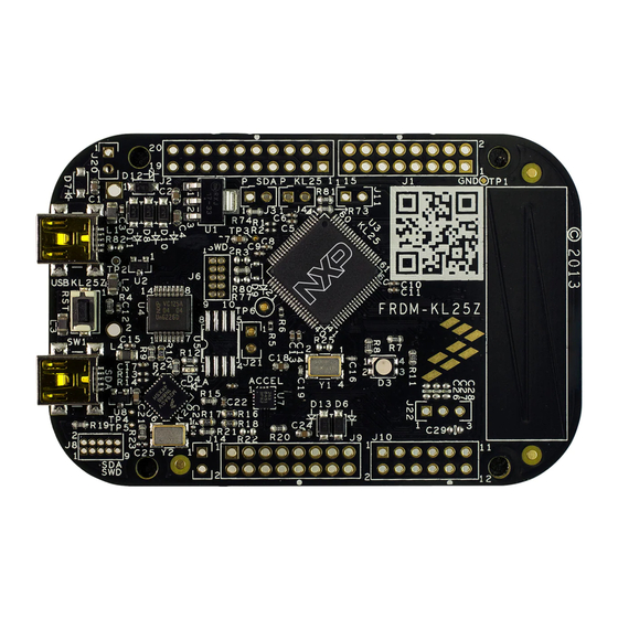
Page 5: Figure 2. Frdm-Kl25Z Feature Call-Outs (Preliminary)
Figure 2. FRDM-KL25Z Feature Call-outs (Preliminary) The FRDM-KL25Z features two microcontrollers (MCUs): the target MCU and a serial and debug adapter (OpenSDA) MCU. The target MCU is a Kinetis L Series KL2 family device, the KL25Z128VLK4. The OpenSDA MCU is a Kientis K Series K20 family device, the K20DX128VFM5. -
Page 6: Frdm-Kl25Z Hardware Description
FRDM-KL25Z Hardware Description Power Supply The FRDM-KL25Z offers a design with multiple power supply options. It can be powered from either of the USB connectors, the V pin on the I/O header, an on-board coin cell battery, or an off-board 1.71- 3.6V supply from the 3.3V pin on the I/O header. -
Page 7: Figure 3. Power Supply Schematic
Coin cell battery supply voltage. Sources power to the P3V3 supply P3V3_BATT rail through a back drive protection Schottky diode. Main supply rail for the FRDM-KL25Z assembly. May be sourced from P3V3 P3V3_VREG, P3V3_BATT, or directly from the I/O headers (J9 pin 8) KL25Z MCU supply. -
Page 8: Serial And Debug Adapter (Opensda)
The Kinetis KL2 microcontrollers feature an on-chip oscillator compatible with three ranges of input crystal or resonator frequencies: 32-40 kHz (low freq. mode), 3-8 MHz (high freq. mode, low range) and 8-32 MHz (high freq. mode, high range). The KL25Z128 on the FRDM-KL25Z is clocked from an 8 MHz crystal. -
Page 9: 3-Axis Accelerometer
Arduino Compatibility The I/O headers on the FRDM-KL25Z are arranged to allow compatibility with peripheral boards (know as shields) that connect to Arduino and Arduino-compatible microcontroller boards. The outer rows of pins (the even numbered pins) on the headers share the same mechanical spacing and placement as the I/O headers on the Arduino Uno Revision 3 board design. - Page 10 <<To Do: add note about 3.3V vs. 5V systems and IOREF pin >> FRDMKL25ZUM FRDM-KL25Z User Manual Page 10 of 10...
Need help?
Do you have a question about the FRDM-KL25Z and is the answer not in the manual?
Questions and answers