Table of Contents
Advertisement
Instruction Manual
High Performance, Multifunction Inverter
Thank you for purchasing our FRENIC-MEGA series of inverters.
• This product is designed to drive a three-phase induction motor. Read through this instruction manual and be familiar with
the handling procedure for correct use.
• Improper handling might result in incorrect operation, a short life, or even a failure of this product as well as the motor.
• Deliver this manual to the end user of this product. Keep this manual in a safe place until this product is discarded.
• For how to use an optional device, refer to the instruction and installation manuals for that optional device.
Fuji Electric Systems Co., Ltd.
INR-SI47-1335-E
CTi Automation - Phone: 800.894.0412 - Fax: 208.368.0415 - Web: www.ctiautomation.net - Email: info@ctiautomation.net
Advertisement
Table of Contents
Troubleshooting

Related Manuals for Fuji Electric FRENIC-MEGA


Summary of Contents for Fuji Electric FRENIC-MEGA
-
Page 1: Instruction Manual
Instruction Manual High Performance, Multifunction Inverter Thank you for purchasing our FRENIC-MEGA series of inverters. • This product is designed to drive a three-phase induction motor. Read through this instruction manual and be familiar with the handling procedure for correct use. - Page 2 Copyright © 2008 Fuji Electric Systems Co., Ltd. All rights reserved. No part of this publication may be reproduced or copied without prior written permission from Fuji Electric Systems Co., Ltd. All products and company names mentioned in this manual are trademarks or registered trademarks of their respective holders.
-
Page 3: Safety Precautions
Have this manual delivered to the end user of this product. Keep this manual in a safe place until this product is discarded. Listed below are the other materials related to the use of the FRENIC-MEGA. Read them in conjunction with this manual as necessary. - Page 4 Wiring • If no zero-phase current (earth leakage current) detective device such as a ground-fault relay is installed in the upstream power supply line in order to avoid the entire power supply system's shutdown undesirable to factory operation, install a residual-current-operated protective device (RCD)/earth leakage circuit breaker (ELCB) individually to inverters to break the individual inverter power supply lines only.
- Page 5 • If the user configures the function codes wrongly without completely understanding this Instruction Manual and the FRENIC-MEGA User's Manual, the motor may rotate with a torque or at a speed not permitted for the machine. An accident or injuries could occur.
-
Page 6: General Precautions
Maintenance and inspection, and parts replacement • Before proceeding to the maintenance/inspection jobs, turn OFF the power and wait at least five minutes for inverters with a capacity of 22 kW or below, or at least ten minutes for inverters with a capacity of 30 kW or above. - Page 7 Conformity to the Low Voltage Directive in the EU If installed according to the guidelines given below, inverters marked with CE are considered as compliant with the Low Voltage Directive 2006/95/EC. Compliance with European Standards Adjustable speed electrical power drive systems (PDS). Part 5-1: Safety requirements.
- Page 8 Conformity to the Low Voltage Directive in the EU (Continued) 3. When used with the inverter, a molded case circuit breaker (MCCB), residual-current-operated protective device (RCD)/earth leakage circuit breaker (ELCB) or magnetic contactor (MC) should conform to the EN or IEC standards. 4.
- Page 9 Conformity to the Low Voltage Directive in the EU (Continued) Recommended wire size (mm Main circuit MCCB or Main power RCD/ELCB *1 input *2 Inverter type Rated current [L1/R, L2/S, L3/T] Inverter’s grounding [ G] FRN0.4G1 -4 0.75 FRN0.75G1 -4 FRN1.5G1 -4 FRN2.2G1 -4 FRN3.7G1 -4A...
- Page 10 Conformity to the Low Voltage Directive in the EU (Continued) Recommended wire size (mm Main circuit MCCB or Main power RCD/ELCB *1 input *2 Inverter type Rated current [L1/R, L2/S, L3/T] Inverter’s grounding [ G] 185×2 185×2 185×2 FRN220G1 -4 240×2 FRN280G1 -4 240×2...
- Page 11 Conformity with UL standards and CSA standards (cUL-listed for Canada) UL/cUL-listed inverters are subject to the regulations set forth by the UL standards and CSA standards (cUL-listed for Canada) by installation within precautions listed below. 1. Solid state motor overload protection (motor protection by electronic thermal overload relay) is provided in each model. Use function codes F10 to F12 to set the protection level.
- Page 12 Conformity with UL standards and CSA standards (cUL-listed for Canada) (continued) 7. Install UL certified fuses or circuit breaker between the power supply and the inverter, referring to the table below. Required torque lb-in Wire size AWG (mm (N m) Main terminal L1/R, L2/S, L3/T U, V, W...
- Page 13 Conformity with UL standards and CSA standards (cUL-listed for Canada) (continued) Required torque lb-in Wire size AWG (mm (N m) Main terminal L1/R, L2/S, L3/T U, V, W Inverter type FRN0.4G1 -4 10.6 (1.2) 0.75 FRN0.75G1 -4 FRN1.5G1 -4 (2.1) (2.1) (2.1) (2.1)
- Page 14 Conformity with UL standards and CSA standards (cUL-listed for Canada) (continued) Required torque Wire size AWG (mm lb-in (N m) Main terminal L1/R, L2/S, L3/T U, V, W Inverter type 300×2 350×2 (152×2) (177×2) FRN220G1 -4 400×2 400×2 (203×2) (203×2) 250×2 300×2 FRN280G1 -4...
-
Page 15: Table Of Contents
9.5.2 Points for consideration when using the 4.1.13 Preparation for practical operation ....4-16 4.2 Special Operations ..........4-16 FRENIC-MEGA series in a system to be certified 4.2.1 Jogging operation..........4-16 by the Low Voltage Directive in the EU ... 9-4 4.2.2 Remote and local modes .........4-16 9.6 Compliance with EN954-1, Category 3.... -
Page 16: Chapter 1 Before Using The Inverter
1 to 9: January to September X, Y, or Z: October, November, or December Production year: Last digit of year If you suspect the product is not working properly or if you have any questions about your product, contact your Fuji Electric representative. -
Page 17: External View And Terminal Blocks
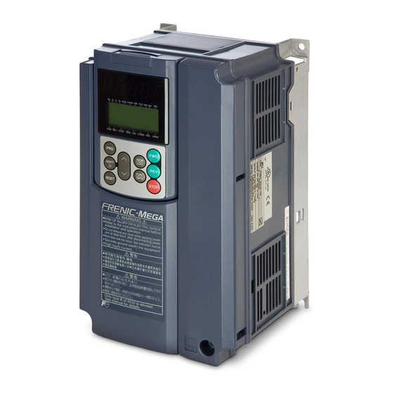
1.2 External View and Terminal Blocks (1) Outside and inside views (a) FRN11G1 -4 (b) FRN220G1 -4 Figure 1.2 Outside and Inside Views of Inverters (2) Warning plates and label (a) FRN11G1 -4 (b) FRN220G1 -4 Figure 1.3 Warning Plates and Label Note: A box ( ) in the above figures replaces S or E depending on the enclosure. -
Page 18: Precautions For Using Inverters
Install the inverter in an environment that satisfies the requirements listed in Table 2.1 in Chapter 2. Fuji Electric strongly recommends installing inverters in a panel for safety reasons, in particular, when installing the ones whose enclosure rating is IP00. - Page 19 For an inverter with an output circuit filter installed, the total secondary wiring length should be 400 m or less (100 m or less under the vector control). If further longer secondary wiring is required, consult your Fuji Electric representative. (5) Precautions for surge voltage in driving a motor by an inverter (especially for 400 V class, general-purpose motors) If the motor is driven by a PWM-type inverter, surge voltage generated by switching the inverter component may be superimposed on the output voltage and may be applied to the motor terminals.
- Page 20 DCR models Input power factor Remarks DCR2/4- Approx. 90% to 95% The last letter identifies the capacitance. Exclusively designed for nominal applied motor of 37 kW DCR2/4- Approx. 86% to 90% or above. Select a DCR matching not the inverter but the nominal applied motor. Applicable reactors differ depending upon the selected HD, MD, or LD mode even on the same type of inverters.
- Page 21 If no zero-phase current (earth leakage current) detective device such as a ground-fault relay is installed in the upstream power supply line in order to avoid the entire power supply system's shutdown undesirable to factory operation, install a residual-current-operated protective device (RCD)/earth leakage circuit breaker (ELCB) individually to inverters to break the individual inverter power supply lines only.
- Page 22 Leakage current A high frequency current component generated by insulated gate bipolar transistors (IGBTs) switching on/off inside the inverter becomes leakage current through stray capacitance of inverter input and output wires or a motor. If any of the problems listed below occurs, take an appropriate measure against them. Problem Measures An earth leakage circuit...
- Page 23 Avoid such operation. Synchronous motors It is necessary to take special measures suitable for this motor type. Contact your Fuji Electric representative for details. Single-phase motors Single-phase motors are not suitable for inverter-driven variable speed operation.
-
Page 24: Operating Environment
Chapter 2 MOUNTING AND WIRING THE INVERTER 2.1 Operating Environment Install the inverter in an environment that satisfies the requirements listed in Table 2.1. Table 2.1 Environmental Requirements Table 2.2 Output Current Derating Factor in Relation to Altitude Item Specifications Output current Site location Indoors... - Page 25 To utilize external cooling for inverters with a capacity of 30 kW or above, change the positions of the top and bottom mounting bases from the edge to the center of the inverter as shown in Figure 2.3. Screws differ in size and count for each inverter. Refer to the table below. Table 2.4 Screw Size, Count and Tightening Torque Tightening Base fixing screw...
- Page 26 2.3 Wiring Follow the procedure below. (In the following description, the inverter has already been installed.) 2.3.1 Removing and mounting the front cover and the wiring guide (1) For inverters with a capacity of 22 kW or below First loosen the front cover fixing screw, slide the cover downward holding its both sides, tilt it toward you, and then pull it upward, as shown below.
- Page 27 2.3.2 Screw specifications and recommended wire sizes (1) Arrangement of main circuit terminals The tables and figures given below show the screw specifications and wire sizes. Note that the terminal arrangements differ depending on the inverter types. In each of the figures, two grounding terminals ( G) are not exclusive to the power supply wiring (primary circuit) or motor wiring (secondary circuit).
- Page 28 Grounding terminal for input line, provided only on the EMC filter built-in type Refer to Section 2.3.3 (9). CTi Automation - Phone: 800.894.0412 - Fax: 208.368.0415 - Web: www.ctiautomation.net - Email: info@ctiautomation.net...
- Page 29 Table 2.6 Recommended Wire Sizes Recommended wire size (mm Nominal Inverter type Main circuit power input applied Inverter Braking Grounding (L1/R, L2/S, L3/T) motor output resistor [ G] [P1, P(+)] (kW) [U, V, W] [P(+), DB] HD mode LD mode MD mode w/ DCR w/o DCR...
- Page 30 (2) Arrangement of control circuit terminals (common to all inverter types) Recommended wire size: 0.65 to 0.82 mm (AWG 19 or 18)* * Using wires exceeding the recommended sizes may lift the front cover depending upon the number of wires used, impeding keypad's normal operation. 2.3.3 Wiring precautions Follow the rules below when performing wiring for the inverter.
- Page 31 (8) In some types of inverters, the wires from the main circuit terminal block cannot be straight routed. Route such wires as shown below so that the front cover is set into place. (9) For inverters with a capacity of 500 kW or 630 kW, two L2/S input terminals are arranged vertically to the terminal block.
- Page 32 2.3.4 Wiring of main circuit terminals and grounding terminals This section shows connection diagrams with the Enable input function used. (1) FRN_ _ _G1 -2A/4A, with SINK mode input by factory default CTi Automation - Phone: 800.894.0412 - Fax: 208.368.0415 - Web: www.ctiautomation.net - Email: info@ctiautomation.net...
- Page 33 (2) FRN_ _ _G1 -4E, with SOURCE mode input by factory default CTi Automation - Phone: 800.894.0412 - Fax: 208.368.0415 - Web: www.ctiautomation.net - Email: info@ctiautomation.net 2-10...
- Page 34 *1 Install a recommended molded case circuit breaker (MCCB) or residual-current-operated protective device (RCD)/earth leakage circuit breaker (ELCB) (with overcurrent protection function) in the primary circuit of the inverter to protect wiring. Ensure that the circuit breaker capacity is equivalent to or lower than the recommended capacity. *2 Install a magnetic contactor (MC) for each inverter to separate the inverter from the power supply, apart from the MCCB or RCD/ELCB, when necessary.
- Page 35 Primary grounding terminal ( G) for inverter enclosure Two grounding terminals ( G) are not exclusive to the power supply wiring (primary circuit) or motor wiring (secondary circuit). Be sure to ground either of the two grounding terminals for safety and noise reduction. The inverter is designed for use with safety grounding to avoid electric shock, fire and other disasters.
- Page 36 2) Connecting other external devices A DC link bus of other inverter(s) or a PWM converter is connectable to these terminals. When you need to use the DC link bus terminals P(+) and N(-), consult your Fuji Electric representative. Switching connectors...
- Page 37 400 V class series with 75 kW or above) The standard FRENIC-MEGA series accepts DC-linked power input in combination with a PWM converter. The 200 V class series with 37 kW or above and 400 V class series with 75 kW or above, however, contain AC-driven components such as AC fans.
- Page 38 (e.g., when the protective function is activated), preventing a failure or accident from causing secondary disasters. To drive the inverter with single-phase input power, consult your Fuji Electric representative. Auxiliary control power input terminals R0 and T0 (for inverters with a capacity of 1.5 kW or above) In general, the inverter runs normally without power supplied to the auxiliary control power input terminals R0 and T0.
- Page 39 When connecting a PWM converter with an inverter, do not connect the power supply line directly to terminals R0 and T0. If a PWM is to be connected, insert an insulation transformer or auxiliary B contacts of a magnetic contactor at the power supply side. For connection examples at the PWM converter side, refer to the PWM Converter Instruction Manual.
- Page 40 Table 2.7 lists the symbols, names and functions of the control circuit terminals. The wiring to the control circuit terminals differs depending upon the setting of the function codes, which reflects the use of the inverter. Route wires properly to reduce the influence of noise.
- Page 41 (Needs a pull-up or pull-down resistor. See notes on page 2-20.) 100 kHz: When connected to a pulse generator with complementary transistor output For the settings of the function codes, refer to FRENIC-MEGA User's Manual, Chapter 5 "FUNCTION CODES." (Digital input circuit specifications) Item Min.
- Page 42 Table 2.7 Symbols, Names and Functions of the Control Circuit Terminals (Continued) Symbol Name Functions [EN] Enable input (1) Safety stop function that is compliant with EN954-1, Category 3. This terminal allows the hardware circuit to stop the inserter's output transistor and coast the motor to a stop.
- Page 43 Table 2.7 Symbols, Names and Functions of the Control Circuit Terminals (Continued) Symbol Name Functions Programmable Programmable <Control circuit> <Control circuit> logic controller logic controller SINK [PLC] [PLC] SINK SOURCE SOURCE [X1] to [X7], [X1] to [X7], Photocoupler Photocoupler [FWD], [REV] [FWD], [REV] [CM] [CM]...
- Page 44 Table 2.7 Symbols, Names and Functions of the Control Circuit Terminals (Continued) Symbol Name Functions [Y1] Transistor (1) Various signals such as inverter running, speed/freq. arrival and overload early output 1 warning can be assigned to any terminals, [Y1] to [Y4] by setting function code E20 to E24.
- Page 45 Table 2.7 Symbols, Names and Functions of the Control Circuit Terminals (Continued) Symbol Name Functions [DX+]/ RS-485 A communications port transmits data through the RS-485 multipoint protocol [DX-]/ communications between the inverter and a personal computer or other equipment such as a PLC. [SD] port 2 (For setting of the terminating resistor, refer to Section 2.3.6 "Setting up the slide...
- Page 46 Wiring for control circuit terminals For FRN75G1 -2 , FRN90G1 -2 and FRN132G1 -4 to FRN630G1 -4 (1) As shown in Figure 2.19, route the control circuit wires along the left side panel to the outside of the inverter. (2) Secure those wires to the wiring support, using a cable tie (e.g., Insulok) with 3.8 mm or less in width and 1.5 mm or less in thickness.
- Page 47 Table 2.8 lists function of each slide switch. Table 2.8 Function of Each Slide Switch Switch Function Switches the service mode of the digital input terminals between SINK and SOURCE. ▪ This switches the input mode of digital input terminals [X1] to [X7], [FWD] and [REV] to be used as the SINK or SOURCE mode.
-
Page 48: Mounting And Connecting A Keypad
2.4 Mounting and Connecting a Keypad You can mount a keypad on the panel wall or install one at a remote site (e.g. for operation on hand). Figure 2.21 Mounting a Keypad on the Panel Wall To mount/install a keypad on a place other than in an inverter, the parts listed below are needed. Parts name Model Remarks... - Page 49 Chapter 3 OPERATION USING THE KEYPAD (in the case of remote keypad) 3.1 LED Monitor, Keys and LED Indicators on the Keypad As shown at the right, the keypad consists of a 7-segment four-digit LED monitor, six keys, and five LED LED monitor indicators.
-
Page 50: Overview Of Operation Modes
The USB port with a mini B connector enables the inverter to connect with a PC with a USB port USB cable. 3.2 Overview of Operation Modes FRENIC-MEGA features the following three operation modes. Table 3.2 Operation Modes Operation mode Description After powered ON, the inverter automatically enters this mode. -
Page 51: Running Mode
3.3 Running Mode 3.3.1 Monitoring the running status In Running mode, the fourteen items listed below can be monitored. Immediately after the inverter is turned ON, the monitor item specified by function code E43 is displayed. Press the key to switch between these monitor items. Table 3.3 Monitoring Items Display Function... -
Page 52: Monitoring Light Alarms
Increase the E42 data if the monitored values are unstable and unreadable due to fluctuation of load. 3.3.2 Monitoring light alarms The FRENIC-MEGA identifies abnormal states in two categories--Heavy alarm and Light alarm. If the former occurs, the l-al inverter immediately trips; if the latter occurs, the inverter shows the on the LED monitor and blinks the KEYPAD CONTROL LED but it continues to run without tripping. -
Page 53: Programming Mode
3.4 Programming Mode The Programming mode provides you with these functions--setting and checking function code data, monitoring maintenance information and checking input/output (I/O) signal status. The functions can be easily selected with the menu-driven system. Table 3.4 lists menus available in Programming mode. The leftmost digit (numerals) of each letter string on the LED monitor indicates the corresponding menu number and the remaining three digits indicate the menu contents. - Page 54 ■ Selecting menus to display The menu-driven system allows you to cycle through menus. To cycle through necessary menus only for simple operation, use function code E52 that provides a choice of three display modes as listed below. The factory default (E52 = 0) is to display only three menus--Menu #0 "Quick Setup," Menu #1 "Data Setting" and Menu #7 "Data Copying,"...
- Page 55 1 second or longer in the same way as with the frequency settings. This action is called "Cursor movement." It is possible to change or add function code items subject to quick setup. For details, consult your Fuji Electric representatives.
- Page 56 3.4.4 Monitoring the running status -- Menu #3 "Drive Monitoring" -- Menu #3 "Drive Monitoring" is used to monitor the running status during maintenance and trial running. The display items for "Drive Monitoring" are listed in Table 3.6. Figure 3.3 shows the menu transition in Menu #3 "Drive Monitoring." Figure 3.3 Menu Transition in Menu #3 "Drive Monitoring"...
- Page 57 Table 3.6 "Drive Monitoring" Display Items LED monitor Item Unit Description shows: 3_00 Output frequency Output frequency before slip compensation 3_01 Output frequency Output frequency after slip compensation 3_02 Output current Output current 3_03 Output voltage Output voltage 3_04 Calculated torque Calculated output torque of the motor in % 3_05 Reference frequency...
- Page 58 3_07 3_23 Displaying running status ( ) and running status 2 ( To display the running status and running status 2 in 4-digit hexadecimal format, each state has been assigned to bits 0 to 15 as listed in Tables 3.7 and 3.8. Table 3.9 shows the relationship between each of the status assignments and the LED monitor display.
- Page 59 Hexadecimal expression A 4-bit binary number can be expressed in hexadecimal (1 hexadecimal digit). Table 3.10 shows the correspondence between the two notations. The hexadecimals are shown as they appear on the LED monitor. Table 3.10 Binary and Hexadecimal Conversion Binary Hexadecimal Binary...
- Page 60 Basic key operation To check the status of the I/O signals, set function code E52 to "2" (Full-menu mode) beforehand. (1) Turn the inverter ON. It automatically enters Running mode. In that mode, press the key to switch to Programming mode.
- Page 61 On the FRENIC-MEGA, digital input terminals [FWD] and [REV] are assigned to bits 0 and 1, respectively. Terminals [X1] through [X7] are assigned to bits 2 through 10. The bit is set to "1" when the corresponding input terminal is short-circuited (ON), and it is set to "0"...
- Page 62 Displaying control I/O signal terminals under communications control Under communications control, input commands (function code S06) sent via RS-485 or other optional communications can be displayed in two ways: "with ON/OFF of each LED segment" and "in hexadecimal." The content to be displayed is basically the same as that for the control I/O signal terminal status display;...
- Page 63 Table 3.15 Display Items in "Maintenance Information" LED Monitor Item Description shows: Shows the content of the cumulative power-ON time counter of the inverter. Counter range: 0 to 65,535 hours Display: Upper 2 digits and lower 3 digits are displayed alternately. ⇔...
- Page 64 Table 3.15 Display Items in "Maintenance Information" (Continued) LED Monitor Item Description shows: Shows the total number of errors that have occurred in RS-485 Number of RS-485 communication (COM port 1, connection to keypad) after the power is 5_11 communications errors turned ON.
- Page 65 Table 3.15 Display Items in "Maintenance Information" (Continued) LED Monitor Item Description shows: Shows the content of the cumulative power-ON time counter of motor 4. 5_30 Cumulative run time of motor 4 5_23 The display method is the same as for above.
- Page 66 3.4.7 Reading alarm information -- Menu #6 "Alarm Information" -- Menu #6 "Alarm Information" shows the causes of the past 4 alarms in alarm code. Further, it is also possible to display alarm information that indicates the status of the inverter when the alarm occurred. Figure 3.5 shows the menu transition in Menu #6 "Alarm Information"...
- Page 67 Table 3.16 Display Items in "Alarm Information" LED monitor shows: Item Description (item No.) 6_00 Output frequency Output frequency before slip compensation 6_01 Output current Output current 6_02 Output voltage Output voltage 6_03 Calculated torque Calculated motor output torque 6_04 Reference frequency Frequency specified by frequency command Shows the rotational direction currently specified.
- Page 68 Table 3.16 Display Items in "Alarm Information" (Continued) LED monitor shows: Item Description (item No.) Running status 2 as four hexadecimal digits. 6_22 3_07 Running status 2 Refer to " Displaying running status ( ) and running status 2 3_23 )"...
- Page 69 Basic keying operation (1) Turn the inverter ON. It automatically enters Running mode. In that mode, press the key to switch to Programming mode. The function selection menu appears. 'cpy (2) Use the keys to display "Data Copying" ( read (3) Press the key to proceed to the list of data copying functions (e.g.
- Page 70 • The function codes stored in the keypad and ones registered in the inverter are not compatible with each other. (Either of the two may have been revised or upgraded in a non-standard or incompatible manner. Consult your Fuji Electric representative.)
-
Page 71: Alarm Mode
3.5 Alarm Mode If an abnormal condition arises, the protective function is invoked and issues an alarm, then the inverter automatically enters Alarm mode. At the same time, an alarm code appears on the LED monitor. Releasing the alarm and switching to Running mode Remove the cause of the alarm and press the key to release the alarm and return to Running mode. -
Page 72: Usb Connectivity
3.6 USB Connectivity The keypad has a USB port (mini B connector) on its face. To connect a USB cable, open the USB port cover as shown below. Connecting the inverter to a PC with a USB cable enables remote control from FRENIC Loader. On the PC running FRENIC Loader, it is possible to edit, check, manage, and monitor the function code data in real-time, to start or stop the inverter, and to monitor the running or alarm status of the inverter. -
Page 73: Chapter 4 Running The Motor
Chapter 4 RUNNING THE MOTOR 4.1 Running the Motor for a Test 4.1.1 Test run procedure Make a test run of the motor using the flowchart given below. This chapter describes the test run procedure with motor 1 dedicated function codes that are marked with an asterisk (*). For motors 2 to 4, replace those asterisked function codes with respective motor dedicated ones. - Page 74 4.1.4 Switching between HD, MD and LD drive modes The FRENIC-MEGA series of inverters is applicable to three ratings--high duty (HD) for heavy load applications, medium duty (MD) for medium load ones, and low duty (LD) for light load ones. (The MD mode is available for three phase 400 V class series of inverters with a capacity of 90 kW or above.)
- Page 75 Switching to the MD/LD mode does not automatically change the motor rated capacity (P02*) to the one for the motor with one rank higher capacity, so configure the P02* data to match the applied motor rating as required. 4.1.5 Selecting a desired motor drive control The FRENIC-MEGA supports the following motor drive control. F42* Basic...
- Page 76 H68 * enables or disables the slip compensation function according to the motor driving conditions. Motor driving conditions Motor driving frequency zone H68* data Accl/Decel Constant speed Base frequency or below Above the base frequency Enable Enable Enable Enable Disable Enable Enable Enable...
- Page 77 The final performance should be determined by adjusting the speed control system or other elements with the inverter being connected to the machinery (load). If you have any questions, contact your Fuji Electric representative. Output...
- Page 78 When accessing the function code P02*, take into account that changing the P02* data automatically updates the data of the function codes P03*, P06* to P23*, P53* to P56*, and H46. The motor rating should be specified properly when performing auto-torque boost, torque calculation monitoring, auto energy saving, torque limiting, automatic deceleration (anti-regenerative control), auto search for idling motor speed, slip compensation, torque vector control, droop control, or overload stop.
- Page 79 - The maximum frequency or the frequency limiter (high) has limited tuning operation. Other errors An undervoltage or any other alarm has occurred. If any of these errors occurs, remove the error cause and perform tuning again, or consult your Fuji Electric representative.
- Page 80 If a filter other than the Fuji optional output filter (OFL - - A) is connected to the inverter's output (secondary) circuit, the tuning result cannot be assured. When replacing the inverter connected with such a filter, make a note of the old inverter’s settings for the primary resistance %R1, leakage reactance %X, no-load current, and rated slip frequency, and specify those values to the new inverter’s function codes.
- Page 81 Tuning procedure (1) Selection of tuning type Check the machinery conditions and perform the "tuning while the motor is rotating under vector control" (P04*=3). Adjust the acceleration and deceleration times (F07 and F08) in view of the motor rotation. And specify the rotation direction that matches the actual rotation direction of the machinery.
- Page 82 - The maximum frequency or the frequency limiter (high) has limited tuning operation. Other errors An undervoltage or any other alarm has occurred. If any of these errors occurs, remove the error cause and perform tuning again, or consult your Fuji Electric representative. 4-10...
- Page 83 If a filter other than the Fuji optional output filter (OFL - - A) is connected to the inverter's output (secondary) circuit, the tuning result cannot be assured. When replacing the inverter connected with such a filter, make a note of the old inverter’s settings for the primary resistance %R1, leakage reactance %X, no-load current, and rated slip frequency, and specify those values to the new inverter’s function codes.
- Page 84 4.1.10 Function code basic settings < 5 > Driving a Fuji general-purpose motor under V/f control with speed sensor (F42* = 3) or dynamic torque vector control with speed sensor (F42* = 4) requires configuring the following basic function codes. (Refer to Figure 4.1 on page 4-1.) Select Fuji standard 8- or 6-series motors with the function code P99*.
- Page 85 Factory default Function Name Function code data code FRN_ _ _G1 -2A/4A FRN_ _ _G1 -4E 200 V class series: 200 V class series: ― 60.0 (Hz) f 04 Base frequency 1 400 V class series: 400 V class series: 50.0 (Hz) 50.0 (Hz) 200 V class series:...
- Page 86 An undervoltage or any other alarm has occurred. If any of these errors occurs, remove the error cause and perform tuning again, or consult your Fuji Electric representative. If a filter other than the Fuji optional output filter (OFL - - A) is connected to the inverter's output (secondary) circuit, the tuning result cannot be assured.
- Page 87 The speed limiting function serves as an overspeed level barrier, or as a speed limiter under torque control. For details of the speed limiting function, refer to the FRENIC-MEGA User's Manual. ------------------------------------------------------------------------------------------------------------------------------------------------------- <...
-
Page 88: Special Operations
4.1.13 Preparation for practical operation After verifying normal motor running with the inverter in a test run, connect the motor with the machinery and perform wiring for practical operation. (1) Configure the application related function codes that operate the machinery. (2) Check interfacing with the peripheral circuits. -
Page 89: External Run/Frequency Command
Run commands from the keypad in the local mode The table below shows the input procedures of run commands from the keypad in the local mode. When F02 data (run command) is: Input procedures of run commands from keypad 0: Enable keys on keypad Pressing the key runs the motor in the direction specified by command... -
Page 90: Chapter 5 Function Codes
5.1 Function Code Tables Function codes enable the FRENIC-MEGA series of inverters to be set up to match your system requirements. Each function code consists of a 3-letter alphanumeric string. The first letter is an alphabet that identifies its group and the following two letters are numerals that identify each individual code in the group. - Page 91 Drive control The FRENIC-MEGA runs under any of the following drive controls. Some function codes apply exclusively to the specific drive control, which is indicated by letters Y (Applicable) and N (Not applicable) in the "Drive control" column in the function code tables given on the following pages.
- Page 92 The following tables list the function codes available for the FRENIC-MEGA series of inverters. F codes: Fundamental Functions Drive control Refer Default Code Name Data setting range setting Torque page: control F00 Data Protection 0: Disable both data protection and digital reference...
- Page 93 Drive control Refer Default Code Name Data setting range setting Torque page: control F26 Motor Sound (Carrier frequency) 0.75 to 16 kHz (HD-mode inverters with 55 kW or below 5-53 and LD-mode ones with 18.5 kW or below (Asia) 0.75 to 10 kHz (HD-mode inverters with 75 to 400 kW and LD-mode ones with 22 to 55 kW) (EU) 0.75 to 6 kHz (HD-mode inverters with 500 and 630 kW...
- Page 94 E codes: Extension Terminal Functions Drive control Refer Default Code Name Data setting range setting Torque page: control Selecting function code data assigns the corresponding 5-67 function to terminals [X1] to [X7] as listed below. E01 Terminal [X1] Function 0 (1000): Select multi-frequency (0 to 1 steps) (SS1) E02 Terminal [X2] Function...
- Page 95 Drive control Refer to Default Code Name Data setting range page: setting Torque control E16 Torque Limiter 2-1 -300% to 300%; 999 (Disable) 5-57 E17 Torque Limiter 2-2 -300% to 300%; 999 (Disable) 5-77 Selecting function code data assigns the corresponding 5-77 function to terminals [Y1] to [Y5A/C] and [30A/B/C] as listed below.
- Page 96 Drive control Refer to Default Code Name Data setting range page: setting Torque control E30 Frequency Arrival (Hysteresis width) 0.0 to 10.0 Hz 5-82 E31 Frequency Detection 1 (Level) 0.0 to 500.0 Hz (Hysteresis width) 0.0 to 500.0 Hz E34 Overload Early Warning/Current 0.00 (Disable);...
- Page 97 Drive control Refer to Default Code Name Data setting range page: setting Torque control Selecting function code data assigns the corresponding 5-67 function to terminals [FWD] and [REV] as listed below. 5-92 E98 Terminal [FWD] Function 0 (1000): Select multi-frequency (0 to 1 steps) (SS1) E99 Terminal [REV] Function 1 (1001):...
- Page 98 C codes: Control Functions of Frequency Drive control Refer Default Code Name Data setting range setting Torque page: control C01 Jump Frequency 1 0.0 to 500.0 Hz 5-92 (Hysteresis width) 0.0 to 30.0 Hz C05 Multi-frequency 1 0.00 to 500.00 Hz 0.00 0.00 0.00...
- Page 99 P codes: Motor 1 Parameters Drive control Refer Default Code Name Data setting range setting Torque page: control P01 Motor 1 (No. of poles) 2 to 22 poles Y1 Y2 5-95 (Rated capacity) 0.01 to 1000 kW (when P99 = 0, 2, 3 or 4) Y1 Y2 5-96 0.01 to 1000 HP (when P99 = 1)
- Page 100 Drive control Refer Default Code Name Data setting range setting Torque page: control H09 Starting Mode (Auto search) 0: Disable 5-101 1: Enable (At restart after momentary power failure) 2: Enable (At restart after momentary power failure and at normal start) H11 Deceleration Mode 0: Normal deceleration 1: Coast-to-stop...
- Page 101 Drive control Refer Default Code Name Data setting range setting Torque page: control H61 UP/DOWN Control 0: 0.00 Hz 5-29 (Initial frequency setting) 5-109 1: Last UP/DOWN command value on releasing the run command H63 Low Limiter (Mode selection) 0: Limit by F16 (Frequency limiter: Low) and continue to 5-49 5-109 1: If the output frequency lowers below the one limited by...
- Page 102 Drive control Refer Default Code Name Data setting range setting Torque page: control H97 Clear Alarm Data 0: Disable 5-115 1: Enable (Setting "1" clears alarm data and then returns to "0.") H98 Protection/Maintenance Function 0 to 255: Display data in decimal format (Mode selection) Bit 0: Lower the carrier frequency automatically (0: Disabled;...
- Page 103 Drive control Refer Default Code Name Data setting range setting Torque page: control ― A18 Motor 2 (Auto-tuning) 0: Disable 1: Tune while the motor stops. (%R1, %X and rated slip frequency) 2: Tune while the motor is rotating under V/f control (%R1, %X, rated slip frequency, no-load current, magnetic saturation factors 1 to 5, and magnetic saturation extension factors "a"...
- Page 104 b codes: Motor 3 Parameters Drive control Refer Default Code Name Data setting range setting Torque page: control ― b01 Maximum Frequency 3 25.0 to 500.0 Hz b02 Base Frequency 3 25.0 to 500.0 Hz 50.0 b03 Rated Voltage at Base Frequency 3 0: Output a voltage in proportion to input voltage 80 to 240: Output an AVR-controlled voltage (for 200 V class series)
- Page 105 Drive control Refer Default Name Data setting range setting Torque page: control ― b35 Motor 3 0.0% to 300.0% Y1 Y2 (Magnetic saturation extension factor "a") (Magnetic saturation extension 0.0% to 300.0% Y1 Y2 factor "b") (Magnetic saturation extension 0.0% to 300.0% Y1 Y2 factor "c") b39 Motor 3 Selection...
- Page 106 Drive control Refer Default Code Name Data setting range setting Torque page: control ― r09 DC Braking 4 0.0 to 60.0 Hz (Braking starting frequency) (Braking level) 0% to 100% (HD mode), 0% to 80% (MD/LD mode) (Braking time) 0.00: Disable; 0.01 to 30.00 s 0.00 r12 Starting Frequency 4 0.0 to 60.0 Hz...
- Page 107 Drive control Refer Default Code Name Data setting range setting Torque page: control ― r43 Speed Control 4 0.000 to 5.000 s 0.020 (Speed command filter) (Speed detection filter) 0.000 to 0.100 s 0.005 P (Gain) 0.1 to 200.0 times 10.0 I (Integral time) 0.001 to 9.999 s 0.100...
- Page 108 Drive control Refer Default Code Name Data setting range setting Torque page: control J68 Brake Signal (Brake-OFF current) 0% to 300% 5-129 (Brake-OFF frequency/speed) 0.0 to 25.0 Hz (Brake-OFF timer) 0.0 to 5.0 s (Brake-ON frequency/speed) 0.0 to 25.0 Hz (Brake-ON timer) 0.0 to 5.0 s (Brake-OFF torque) 0% to 300% (Speed selection) 0: Detected speed...
- Page 109 U codes: Application Functions 3 Drive control Refer Default Code Name Data setting range setting Torque page: control U00 Customizable Logic (Mode selection) 0: Disable 5-139 1: Enable (Customizable logic operation) U01 Customizable Logic: (Input 1) 0 (1000): Inverter running (RUN) U02 Step 1 (Input 2) 1 (1001):...
- Page 110 Drive control Refer Default Code Name Data setting range setting Torque page: control 2008 (3008): Output of step 8 (SO08) 5-139 2009 (3009): Output of step 9 (SO09) 2010 (3010): Output of step 10 (SO10) 4001 (5001): Terminal [X1] input signal (X1) 4002 (5002): Terminal [X2] input signal (X2)
- Page 111 Drive control Refer Default Code Name Data setting range setting Torque page: control U26 Customizable Logic: (Input 1) See U01. See U01. 5-139 U27 Step 6 (Input 2) See U02. See U02. (Logic circuit) See U03. (Type of timer) See U04. (Timer) See U05.
- Page 112 Drive control Refer Default Code Name Data setting range setting page: Torque 32 (1032): Pre-excitation (EXITE) 5-139 33 (1033): Reset PID integral and differential components (PID-RST) 34 (1034): Hold PID integral component (PID-HLD) 35 (1035): Select local (keypad) operation (LOC) 36 (1036): Select motor 3 (M3) 37 (1037): Select motor 4...
- Page 113 Drive control Refer Default Code Name Data setting range setting Torque page: control y08 RS-485 Communication 1 0: No detection; 1 to 60 s 5-147 (No-response error detection time) (Response interval) 0.00 to 1.00 s 0.01 (Protocol selection) 0: Modbus RTU protocol 1: FRENIC Loader protocol (SX protocol) 2: Fuji general-purpose inverter protocol y11 RS-485 Communication 2...
- Page 114 Table A Factory Default According to Shipping Destination Shipping destination Asia Function code Name FRN_ _ _G1 -2A FRN_ _ _G1 -4A FRN_ _ _G1 -4E 200 V class series 400 V class series 400 V class series F03, A01, b01, r01 Maximum frequency 60.0 Hz 50.0 Hz...
- Page 115 Table C Motor Parameters The tables given below list the function codes dedicated to motor 1. For motors 2 to 4, replace the function codes with the ones dedicated to the respective motor. Three-phase 200 V class series for Asia (FRN_ _ _G1 -2A) Note: A box ( ) replaces S or E depending on the enclosure.
- Page 116 Table C Motor Parameters (Continued) Three-phase 400 V class series for Asia (FRN_ _ _G1 -4A) Note: A box ( ) replaces S or E depending on the enclosure. CTi Automation - Phone: 800.894.0412 - Fax: 208.368.0415 - Web: www.ctiautomation.net - Email: info@ctiautomation.net 5-27...
- Page 117 Table C Motor Parameters (Continued) Three-phase 400 V class series for EU (FRN_ _ _G1 -4E) Note: A box ( ) replaces S or E depending on the enclosure. CTi Automation - Phone: 800.894.0412 - Fax: 208.368.0415 - Web: www.ctiautomation.net - Email: info@ctiautomation.net 5-28...
-
Page 118: Details Of Function Codes
5.2 Details of Function Codes This section provides the details of the function codes. The descriptions are, in principle, arranged in the order of function code groups and in numerical order. However, highly relevant function codes are collectively described where one of them first appears. - Page 119 Setting up a reference frequency [ 1 ] Using the keypad (F01 = 0 (factory default) or 8) (1) Set F01 data to "0" or "8." This can be done only when the inverter is in Running mode. (2) Press the key to display the current reference frequency.
- Page 120 Gain and bias If F01 = 3 (the sum of [12] + [C1] is enabled), the bias and gain are independently applied to each of the voltage and current inputs given to terminals [12] and [C1], and the sum of the two values is applied as the reference frequency.
- Page 121 In the case of bipolar input (terminal [12] with C35 = 0, terminal [V2] with C45 = 0) Setting C35 and C45 data to "0" enables terminal [12] and [V2] to be used for bipolar input (-10 V to +10 V) respectively.
- Page 122 Initial frequency for the UP/DOWN control when the frequency command source is switched When the frequency command source is switched to the UP/DOWN control from other sources, the initial frequency for the UP/DOWN control is as listed below: Initial frequency for UP/DOWN control Frequency command source Switching command H61 = 0...
- Page 123 Pulse train sign/Pulse train input Forward rotation pulse/Reverse rotation pulse A and B phases with 90 degree phase difference Pulse count factor 1 (d62), Pulse count factor 2 (d63) For the pulse train input, function codes d62 (Command (Pulse rate input), (Pulse count factor 1)) and d63 (Command (Pulse rate input), (Pulse count factor 2)) define the relationship between the input pulse rate and the frequency command (reference).
- Page 124 The pulse train sign, forward/reverse rotation pulse, and A/B phase difference define the polarity of the pulse train input. Combination of the polarity of the pulse train input and the FWD/REV command determines the rotational direction of the motor. The table below shows the relationship between the polarity of the pulse train input and the motor rotational direction.
- Page 125 In addition to the run command sources described above, higher priority command sources including remote and local mode (see Section 7.3.6) and communications link are provided. For details, refer to the block diagrams in Chapter 6 in FRENIC-MEGA User's Manual. Maximum Frequency 1 F03 specifies the maximum frequency to limit the output frequency.
- Page 126 Examples: Normal (linear) V/f pattern V/f pattern with three non-linear points Base Frequency 1 (F04) Data setting range: 25.0 to 500.0 (Hz) Set the rated frequency printed on the nameplate labeled on the motor. Rated Voltage at Base Frequency 1 (F05) Data setting range: 0: Output a voltage in proportion to input voltage (The Automatic Voltage Regulator (AVR) is disabled.) 80 to 240 (V): Output an AVR-controlled voltage for 200 V class series...
- Page 127 Non-linear V/f Patterns 1, 2 and 3 for Frequency (H50, H52 and H65) Data setting range: 0.0 (cancel); 0.1 to 500.0 (Hz) Set the frequency component at an arbitrary point in the non-linear V/f pattern. Setting "0.0" to H50, H52 or H65 disables the non-linear V/f pattern operation. Non-linear V/f Patterns 1, 2 and 3 for Voltage (H51, H53 and H66) Data setting range: 0 to 240 (V): Output an AVR-controlled voltage for 200 V class series 0 to 500 (V): Output an AVR-controlled voltage for 400 V class series...
- Page 128 Under vector control with speed sensor Acceleration/deceleration time Function code Switching factor of acceleration/deceleration time Acceleration/ deceleration time Refer to the descriptions of E01 to E07.) ACC time DEC time The combinations of ON/OFF states of the two Acceleration/ terminal commands RT2 and RT1 offer four deceleration time 1 choices of acceleration/deceleration time 1 to 4.
- Page 129 Acceleration Deceleration Starting zone Ending zone Starting zone Ending zone S-curve (Weak) S-curve (Arbitrary) Setting range: 0 to 100% Acceleration rate Acceleration rate Deceleration rate Deceleration rate for the 1st S-curve for the 2nd S-curve for the 1st S-curve for the 2nd S-curve (Leading edge) (Trailing edge) (Leading edge)
- Page 130 F10 to F12 Electronic Thermal Overload Protection for Motor 1 (Select motor characteristics, Overload detection level, and Thermal time constant) F10 through F12 specify the thermal characteristics of the motor for its electronic thermal overload protection that is used to detect overload conditions of the motor. Upon detection of overload conditions of the motor, the inverter shuts down its output and issues a motor overload alarm to protect motor 1.
- Page 131 Overload detection level (F11) Data setting range: 1 to 135% of the rated current (allowable continuous drive current) of the inverter In general, set the F11 data to the allowable continuous current of motor when driven at the base frequency (i.e. 1.0 to 1.1 times of the rated current of the motor.) To disable the electronic thermal overload protection, set the F11 data to "0.00."...
- Page 132 Restart Mode after Momentary Power Failure (Mode selection) H13 (Restart Mode after Momentary Power Failure (Restart time)) H14 (Restart Mode after Momentary Power Failure (Frequency fall rate)) H15 (Restart Mode after Momentary Power Failure (Continuous running level)) H16 (Restart Mode after Momentary Power Failure (Allowable momentary power failure time)) H92 (Continuity of running (P)) H93 (Continuity of running (I)) F14 specifies the action to be taken by the inverter such as trip and restart in the event of a momentary power failure.
- Page 133 • Under vector control without speed sensor Description Data for F14 Auto search disabled Auto search enabled 0: Trip immediately As soon as the DC link bus voltage drops below the undervoltage detection level due to a momentary power failure, the inverter issues undervoltage alarm and shuts down its output so that the motor enters a coast-to-stop state.
- Page 134 If you enable the "Restart mode after momentary power failure" (Function code F14 = 3, 4, or 5), the inverter automatically restarts the motor running when the power is recovered. Design the machinery or equipment so that human safety is ensured after restarting. Otherwise an accident could occur.
- Page 135 • Auto-restarting after momentary power failure IPF This output signal is ON during the period after the occurrence of momentary power failure until the completion of restart (the output has reached the reference frequency). When the IPF is ON, the motor slows down, so perform necessary operations.
- Page 136 If H16 (Allowable momentary power failure time) is set to "999," restart will take place until the DC link bus voltage drops down to the allowable voltage for restart after a momentary power failure (50 V for 200 V class series and 100 V for 400 V class series).
- Page 137 Restart mode after momentary power failure (Frequency fall rate) (H14) During restart after a momentary power failure, if the inverter output frequency and the idling motor speed cannot be harmonized with each other, an overcurrent will flow, activating the overcurrent limiter. If it happens, the inverter automatically reduces the output frequency to match the idling motor speed according to the reduction rate (Frequency fall rate: Hz/s) specified by H14.
- Page 138 F15, F16 Frequency Limiter (High), Frequency Limiter (Low) H63 Low Limiter (Mode selection) Frequency Limiter (High and Low) (F15, F16) Data setting range: 0.0 to 500.0 (Hz) F15 and F16 specify the upper and lower limits of the output frequency or reference frequency, respectively. The object to which the limit is applied differs depending on the control system.
- Page 139 Braking response mode (H95) H95 specifies the DC braking response mode. When vector control without/with speed sensor is selected, the response is constant. Data for H95 Characteristics Note Slow response. Slows the rising edge of the current, Insufficient braking torque may result at the thereby preventing reverse rotation at the start of DC start of DC braking.
- Page 140 F23 to F25 Starting Frequency 1, Starting Frequency 1 (Holding time), Stop Frequency F38 (Stop Frequency (Detection mode)) F39 (Stop Frequency (Holding time)) H92 (Continuity of Running (P) H93 (Continuity of Running (I) d24 (Zero Speed Control) Under V/f control At the startup of an inverter, the initial output frequency is equal to the starting frequency 1 specified by F23.
- Page 141 Starting Frequency 1 (F23) Data setting range: 0.0 to 60.0 (Hz) F23 specifies the starting frequency at the startup of an inverter. Starting Frequency 1 (Holding time) (F24) Data setting range: 0.00 to 10.00 (s) F24 specifies the holding time for the starting frequency 1. Stop Frequency (F25) Data setting range: 0.0 to 60.0 (Hz) F25 specifies the stop frequency at the stop of the inverter.
- Page 142 F26, F27 Motor Sound (Carrier frequency and Tone) H98 (Protection/Maintenance Function (Mode selection)) Motor Sound (Carrier frequency) (F26) F26 controls the carrier frequency so as to reduce an audible noise generated by the motor or electromagnetic noise from the inverter itself, and to decrease a leakage current from the main output (secondary) wirings. Item Characteristics Remarks...
- Page 143 F29 to F31 Analog Output [FM1] and [FM2] (Mode selection, Voltage adjustment, Function) F32, F34, These function codes allow terminals [FM1] and [FM2] to output monitored data such as the output frequency and the output current in an analog DC voltage or current. The magnitude of such analog voltage or current is adjustable. Mode selection (F29 and F32) F29 and F32 specify the property of the output to terminals [FM1] and [FM2], respectively.
- Page 144 V/f characteristics The FRENIC-MEGA series of inverters offers a variety of V/f patterns and torque boosts, which include V/f patterns suitable for variable torque load such as general fans and pumps and for constant torque load (including special pumps requiring high starting torque).
- Page 145 When the variable torque V/f pattern is selected (F37 = 0 or 3), the output voltage may be low at a low frequency zone, resulting in insufficient output torque, depending on the characteristics of the motor and load. In such a case, it is recommended to increase the output voltage at the low frequency zone using the non-linear V/f pattern.
- Page 146 • Use auto energy saving only where the base frequency is 60 Hz or lower. If the base frequency is set at 60 Hz or higher, you may get a little or no energy saving advantage. The auto energy saving operation is designed for use with the frequency lower than the base frequency.
- Page 147 Torque limiter 1-1, 1-2, 2-1 and 2-2 (F40, F41, E16 and E17) Data setting range: -300 to 300 (%), 999 (Disable) These function codes specify the operation level at which the torque limiters become activated, as the percentage of the motor rated torque.
- Page 148 Torque limiter (Operating conditions) (H73) H73 specifies whether the torque limiter is enabled or disabled during acceleration/deceleration and running at constant speed. Data for H73 During accelerating/decelerating During running at constant speed Enable Enable Disable Enable Enable Disable Torque limiter (Frequency increment limit for braking) (H76) Data setting range: 0.0 to 500.0 (Hz) H76 specifies the increment limit of the frequency in limiting torque for braking.
- Page 149 Torque Limiter (Target quadrants) (H75) H75 selects the configuration of target quadrants (Drive/brake, Forward/reverse rotation) in which the specified torque limiter(s) is activated, from "Drive/brake torque limit," "Same torque limit for all four quadrants," and "Upper/lower torque limits" shown in the table below. Data for H75 Target quadrants 0: Drive/brake...
- Page 150 Torque limiter 1-1, 1-2, 2-1 and 2-2 (F40, F41, E16 and E17) Data setting range: -300 to 300 (%), 999 (Disable) These function codes specify the operation level at which the torque limiters become activated, as the percentage of the motor rated torque.
- Page 151 Torque limiter (Operating conditions) (H73) H73 specifies whether the torque limiter is enabled or disabled during acceleration/deceleration and running at constant speed. Data for H73 During accelerating/decelerating During running at constant speed Enable Enable Disable Enable Enable Disable The torque limiter and current limiter are very similar function each other. If both are activated concurrently, they may conflict each other and cause hunting in the system.
- Page 152 Dynamic torque vector control To get the maximal torque out of a motor, this control calculates the motor torque for the load applied and uses it to optimize the voltage and current vector output. Selecting this control automatically enables the auto torque boost and slip compensation function. This control is effective for improving the system response to external disturbances such as load fluctuation, and the motor speed control accuracy.
- Page 153 U codes values listed in the manual are for standard models and 10% ED models of the braking resistors which Fuji Electric provides. If you use a braking resistor of other maker, confirm the corresponding values with the maker, and set the y codes function codes accordingly.
- Page 154 Depending on the thermal marginal characteristics of the braking resistor, the electronic thermal overload protection feature may act so that the inverter issues the overheat protection alarm even if the actual temperature rise is not large enough. If it happens, review the relationship between the performance index of the braking resistor and settings of related function codes.
- Page 155 Switching between HD, MD and LD drive modes F80 specifies whether to drive the inverter in the high duty (HD), medium duty (MD) or low duty (LD) mode. To change the F80 data, it is necessary to press the" keys" or " keys"...
- Page 156 Refer to the function codes in the "Related function codes" column, if any. The FRENIC-MEGA runs under V/f control, dynamic torque vector control, V/f control with speed sensor, dynamic torque vector control with speed sensor, vector control without speed sensor, or vector control with speed sensor. Some function codes apply exclusively to the specific drive control, which is indicated by letters Y (Applicable) and N (Not applicable) in the "Drive control"...
- Page 157 Function code data Drive control Related Terminal commands assigned Symbol Torque function codes Active ON Active OFF control 1032 Pre-excitation EXITE H84, H85 Reset PID integral and differential 1033 PID-RST J01 to J19, components J56 to J62 1034 Hold PID integral component PID-HLD (See Section 1035...
- Page 158 Terminal function assignment and data setting Coast to a stop -- BX (Function code data = 7) Turning this terminal command ON immediately shuts down the inverter output so that the motor coasts to a stop without issuing any alarms. Reset alarm -- RST (Function code data = 8) Turning this terminal command ON clears the ALM state--alarm output (for any fault).
- Page 159 Operation Schemes • When the motor speed remains almost the same during coast-to-stop: • When the motor speed decreases significantly during coast-to-stop (with the current limiter activated): • Secure more than 0.1 second after turning ON the "Switch to commercial power" signal before turning ON a run command.
- Page 160 Example of Sequence Circuit Note 1) Emergency switch Manual switch provided for the event that the motor drive source cannot be switched normally to the commercial power due to a serious problem of the inverter Note 2) When any alarm has occurred inside the inverter, the motor drive source will automatically be switched to the commercial power.
- Page 161 Example of Operation Time Scheme Alternatively, you may use the integrated sequence by which some of the actions above are automatically performed by the inverter itself. For details, refer to the description of ISW50 and ISW60 . ■ Cancel PID control -- Hz/PID (Function code data = 20) Turning this terminal command ON disables the PID control.
- Page 162 • When the inverter is driven by an external analog frequency command sources (terminals [12], [C1] and [V2]): Switching normal/inverse operation can apply only to the analog frequency command sources (terminals [12], [C1] and [V2]) in frequency command 1 (F01) and does not affect frequency command 2 (C30) or UP/DOWN control. As listed below, the combination of the "Selection of normal/inverse operation for frequency command 1"...
- Page 163 ■ Enable integrated sequence to switch to commercial power (50 Hz) and (60 Hz) -- ISW50 and ISW60 (Function code data = 40 and 41) With the terminal command ISW50 or ISW60 assigned, the inverter controls the magnetic contactor that switches the motor drive source between the commercial power and the inverter output according to the integrated sequence.
- Page 164 Timing Scheme Switching from inverter operation to commercial-power operation ISW50 / ISW60 : ON → OFF (1) The inverter output is shut OFF immediately (Power gate IGBT OFF) (2) The inverter primary circuit SW52-1 and the inverter secondary side SW52-2 are turned OFF immediately. (3) If a run command is present after an elapse of t1 (0.2 sec + time specified by H13), the commercial power circuit SW88 is turned ON.
- Page 165 Examples of Sequence Circuits 1) Standard sequence 2) Sequence with an emergency switching function F codes E codes C codes P codes H codes A codes b codes r codes J codes d codes U codes y codes CTi Automation - Phone: 800.894.0412 - Fax: 208.368.0415 - Web: www.ctiautomation.net - Email: info@ctiautomation.net 5-76...
- Page 166 3) Sequence with an emergency switching function --Part 2 (Automatic switching by the alarm output issued by the inverter) ■ Cancel PG alarm-- PG-CCL (Function code data = 77) When this terminal command is ON, the PG wire break alarm is ignored. Use this terminal command when switching PG wires for switching motors, for example, to prevent it from being detected as PG wire break.
- Page 167 Refer to the function codes or signals in the "Related function codes/signals (data)" column, if any. The FRENIC-MEGA runs under V/f control, dynamic torque vector control, V/f control with speed sensor, dynamic torque vector control with speed sensor, vector control without speed sensor, or vector control with speed sensor. Some function codes apply exclusively to the specific drive control, which is indicated by letters Y (Applicable) and N (Not applicable) in the "Drive control"...
- Page 168 Function code data Drive control Related function Functions assigned Symbol Torque codes/signals Active ON Active OFF control (data) 1048 Motor 1 selected SWM1 1049 Motor 2 selected SWM2 A42, b42, r42 1050 Motor 3 selected SWM3 1051 Motor 4 selected SWM4 ...
- Page 169 Inverter output limiting -- IOL (Function code data = 5) Inverter output limiting with delay -- IOL2 (Function code data = 22) The output signal IOL comes ON when the inverter is limiting the output frequency by activating any of the following actions (minimum width of the output signal: 100 ms).
- Page 170 Under PID control -- PID-CTL (Function code data = 43) his output signal comes ON when PID control is enabled ("Cancel PID control" ( Hz/PID ) = OFF) and a run command is ON. (Refer to the description of J01.) When PID control is enabled, the inverter may stop due to the slow flowrate stopping function or other reasons, with the PID-CTL signal being ON.
- Page 171 Frequency Arrival (Hysteresis width) Output Assigned Operating condition 1 Operating condition 2 signal data FAR always goes OFF when run commands are Both signals come ON when the OFF or the reference speed is "0." difference between the output frequency (estimated/detected speed) When run commands are OFF, the reference and the reference frequency (reference speed is regarded as "0,"...
- Page 172 E34, E35 Overload Early Warning/Current Detection (Level and Timer) E37, F38 (Current Detection 2/Low Current Detection (Level and Timer)) E55, E56 (Current Detection 3 (Level and Timer)) These function codes define the detection level and time for the "Motor overload early warning" OL , "Current detected" ID , "Current detected 2"...
- Page 173 E40, E41 PID Display Coefficient A, B These function codes specify PID display coefficients A and B to convert a PID command (process command or dancer position command) and its feedback into mnemonic physical quantities to display. - Data setting range: -999 to 0.00 to 9990 for PID display coefficients A and B Display coefficients for PID process command and its feedback (J01 = 1 or 2) E40 specifies coefficient A that determines the display value at 100% of the PID process command or its feedback, and E41 specifies coefficient B that determines the display value at 0%.
- Page 174 Display coefficients for PID dancer position command and its feedback (J01 = 3) Under the PID dancer control, the PID command and its feedback operate within the range ± 100%, so specify the value at +100% of the PID command or its feedback as coefficient A with E40, and the value at -100% as coefficient B with E41.
- Page 175 LED Monitor (Item selection) E48 (LED Monitor (Speed monitor item)) E43 specifies the running status item to be monitored and displayed on the LED monitor. Specifying the speed monitor with E43 provides a choice of speed-monitoring formats selectable with E48 (LED Monitor).
- Page 176 LED Monitor (Display when stopped) E44 specifies whether the specified value (data = 0) or the output value (data = 1) to be displayed on the LED monitor of the keypad when the inverter is stopped. The monitored item depends on the E48 (LED monitor, Speed monitor item) setting as shown below.
- Page 177 LCD Monitor (Language selection) E46 specifies the language to display on the multi-function keypad as follows: Data for E46 Language (TP-G1-J1) Language (TP-G1-C1) Japanese Chinese English English German Japanese French Korean Spanish Italian LCD Monitor (Contrast control) E47 adjusts the contrast of the LCD monitor on the multi-function keypad as follows: Data for E47 0, 1, 2, 3, 4, 5, 6, 7, 8, 9, 10 Contrast...
- Page 178 The menus available on the standard keypad are described below. LED monitor Menu # Menu Main functions shows: Displays only basic function codes to customize the inverter *fn: "Quick Setup" operation. !f__ F codes (Fundamental functions) !e__ E codes (Extension terminal functions) !c__ C codes (Control functions) !p__...
- Page 179 E61 to E63 Terminal [12] Extended Function Terminal [C1] Extended Function Terminal [V2] Extended Function E61, E62, and E63 define the function of the terminals [12], [C1], and [V2], respectively. There is no need to set up these terminals if they are to be used for frequency command sources. Data for E61, Input assigned to Description...
- Page 180 In the diagram above, f1 is the level of the analog frequency command sampled at any given time. The sampling is repeated at regular intervals to continually monitor the wiring connection of the analog frequency command. - Data setting range: 0 (Decelerate to stop), 20 to 120%, 999 (Disable) Avoid an abrupt voltage or current change for the analog frequency command.
- Page 181 In the inverter’s low frequency operation, as a substantial error in torque calculation occurs, no low torque can be detected within the operation range at less than 20% of the base frequency (F04). (In this case, the result of recognition before entering this operation range is retained.) The U-TL signal goes off when the inverter is stopped.
- Page 182 Multi-frequency 1 to 15 (C05 through C19) Data setting range: 0.00 to 500.00 (Hz) The combination of SS1 , SS2 , SS4 and SS8 and the selected frequencies are as follows. Selected frequency command Other than multi-frequency * C05 (multi-frequency 1) C06 (multi-frequency 2) C07 (multi-frequency 3) C08 (multi-frequency 4)
- Page 183 ■ Starting jogging operation Pressing the key or turning the FWD or REV terminal command ON starts jogging. In jogging with the key, the inverter jogs only when the key is held down. Releasing the key decelerates to stop. To start jogging operation by simultaneously entering the JOG terminal command and a run command (e.g., FWD ), the input delay time between the two commands should be within 100 ms.
- Page 184 5.2.4 P codes (Motor 1 Parameters) The FRENIC-MEGA drives the motor under V/f control, dynamic torque vector control, V/f control with speed sensor, dynamic torque vector control with speed sensor, vector control without speed sensor, or vector control with speed sensor, which can be selected with function codes.
- Page 185 Motor 1 (Rated capacity) P02 specifies the rated capacity of the motor. Enter the rated value given on the nameplate of the motor. Data for P02 Unit Function When P99 (Motor 1 Selection) = 0, 2, 3 or 4 0.01 to 1000 When P99 (Motor 1 Selection) = 1 When accessing function code P02 with the keypad, take into account that the P02 data automatically updates the data of function codes P03, P06 through P23, P53 through P56, and H46.
- Page 186 P09 or P11, respectively, to improve output torque accuracy. P10 determines the response time for slip compensation. Basically, there is no need to modify the default setting. If you need to modify it, consult your Fuji Electric representatives. Function codes...
- Page 187 Motor 1 (Rated slip frequency) P12 specifies rated slip frequency. Obtain the appropriate values from the test report of the motor or by calling the manufacturer of the motor. Performing auto-tuning automatically sets these parameters. • Rated slip frequency: Convert the value obtained from the motor manufacturer to Hz using the following expression and enter the converted value.
- Page 188 5.2.5 H codes (High Performance Functions) Data Initialization H03 initializes the current function code data to the factory defaults or initializes the motor parameters. To change the H03 data, it is necessary to press the keys or keys (simultaneous keying). Data for H03 Function Disable initialization (Settings manually made by the user will be retained.)
- Page 189 Number of reset times (H04) Data setting range: 0 (Disable), 1 to 10 (times) H04 specifies the number of reset times for the inverter to automatically attempt to escape the tripped state. If the "auto-reset" function has been specified, the inverter may automatically restart and run the motor stopped due to a trip fault, depending on the cause of the tripping.
- Page 190 Acceleration/Deceleration Pattern (Refer to F07.) Rotational Direction Limitation H08 inhibits the motor from running in an unexpected rotational direction due to miss-operation of run commands, miss-polarization of frequency commands, or other mistakes. Data for H08 Function Disable Enable (Reverse rotation inhibited) Enable (Forward rotation inhibited) Under vector control, some restrictions apply to the speed command.
- Page 191 Starting Mode (Auto search delay time 1) (H49) Data setting range: 0.0 to 10.0 (s) Auto search for the idling motor speed will become unsuccessful if it is done while the motor retains residual voltage. It is, therefore, necessary to leave the motor for an enough time for residual voltage to disappear. H49 specifies that time (0.0 to 10.0 sec.).
- Page 192 Torque Limiter (Mode selection) d32, d33 (Torque Control, Speed limits 1 and 2) When "Vector control without speed sensor" or "Vector control with speed sensor" is selected, the inverter can limit the motor-generating torque according to a torque command sent from external sources. Torque Limiter (Mode selection) (H18) H18 specifies whether to enable or disable the torque limiter.
- Page 193 Running/stopping the motor Under torque control, the inverter does not control the speed, so it does not perform acceleration or deceleration by soft-start and stop (acceleration/deceleration time) at the time of startup and stop. Turning ON a run command starts the inverter to run and outputs the commanded torque. Turning it OFF stops the inverter so that the motor coasts to a stop.
- Page 194 Connect the PTC thermistor as shown below. The voltage obtained by dividing the input voltage on terminal [V2] with a set of internal resistors is compared with the detection level voltage specified by H27. <Control circuit> [13] +10 VDC Resistor (Operation level) 27kΩ...
- Page 195 Command sources selectable Command sources Description Sources except RS-485 communications link and fieldbus Inverter itself Frequency command source: Specified by F01/C30, or multi-frequency command Run command source: Via the keypad or digital input terminals selected by F02 RS-485 communications link Via the standard RJ-45 port used for connecting a keypad (port 1) RS-485 communications link...
- Page 196 H42, H43 Capacitance of DC Link Bus Capacitor, Cumulative Run Time of Cooling Fan Cumulative Run Time of Capacitors on Printed Circuit Boards H47 (Initial Capacitance of DC Link Bus Capacitor) H98 (Protection/Maintenance Function) Life prediction function The inverter has the life prediction function for some parts which measures the discharging time or counts the voltage applied time, etc.
- Page 197 H44, H78 Startup Counter for Motor 1, Maintenance Interval (M1) H79, H94 Preset Startup Count for Maintenance (M1), Cumulative Motor Run Time 1 Cumulative motor run time 1 (H94) Operating the keypad can display the cumulative run time of motor 1. This feature is useful for management and maintenance of the mechanical system.
- Page 198 0 N·m in both the deceleration and constant speed running phases. FRENIC-MEGA series of inverters have two braking control modes; torque limit control and DC link bus voltage control. Understand the feature of each control and select the suitable one.
- Page 199 In addition, during deceleration triggered by turning the run command OFF, the anti-regenerative control increases the output frequency so that the inverter may not stop the load depending on the load state (huge moment of inertia, for example). To avoid that, H69 provides a choice of cancellation of the anti-regenerative control to apply when three times the specified deceleration time is elapsed, thus decelerating the motor forcibly.
- Page 200 In cases where the power is supplied via a PWM converter or the inverter is connected via the DC link bus, there is no alternate-current input. In such cases, set H72 data to "0," otherwise the inverter cannot operate. If you use a single-phase power supply, contact your Fuji Electric representative. H73 to H75 Torque Limiter (Operating conditions, Control target, and Target quadrants) (Refer to F40.)
- Page 201 H81, H82 Light Alarm Selection 1 and 2 If the inverter detects a minor abnormal state "light alarm", it can continue the current operation without tripping while l-al l-al displaying the "light alarm" indication on the LED monitor. In addition to the indication , the inverter blinks the KEYPAD CONTROL LED and outputs the "light alarm"...
- Page 202 Table 5.1 Light Alarm Selection 1 (H81), Bit Assignment of Selectable Factors Code Content Code Content ― ― Overload of motor 3 ― ― Overload of motor 2 RS-485 communications error Overload of motor 1 (COM port 2) RS-485 communications error Braking resistor overheated (COM port 1) ―...
- Page 203 H84, H85 Pre-excitation (Initial level, Time) A motor generates torque with magnetic flux and torque current. Lag elements of the rising edge of magnetic flux causes a phenomenon in which enough torque is not generated at the moment of the motor start. To obtain enough torque even at the moment of motor start, enable the pre-excitation with H84 and H85 so that magnetic flux is established before a motor start.
- Page 204 PID Feedback Wire Break Detection Using the terminal [C1] (current input) for PID feedback signal enables wire break detection and alarm ( ) issuance. H91 specifies whether the wire break detection is enabled, or the duration of detection. (The inverter judges an input current to the terminal [C1] below 2 mA as a wire break.) - Data setting range: 0.0 (Disable alarm detection) 0.1 to 60.0 s (Detect wire break and issue...
- Page 205 In configurations where only a light load is driven or a DC reactor is connected, phase loss or line-to-line voltage unbalance may not be detected because of the relatively small stress on the apparatus connected to the main circuit. Output phase loss protection ( ) (Bit 2) Upon detection of phase loss in the output while the inverter is running, this feature stops the inverter and displays an alarm...
- Page 206 5.2.6 A codes (Motor 2 Parameters), b codes (Motor 3 Parameters), r codes (Motor 4 Parameters) The FRENIC-MEGA can switch control parameters even when it is running so that a single inverter can drive four motors by switching them or turn the energy saving operation ON or OFF for the setup change (e.g., gear switching) that causes the moment of inertia of the machinery to change.
- Page 207 If A42, b42 or r42 is set to "0" (Motor (Switch to the 2nd, 3rd or 4th motor)), the combination of M2 , M3 and M4 switches the motor to any of the 2nd to 4th motors and also switches the function code group enabled to the one corresponding to the selected motor, as listed in Table 5.5.
- Page 208 Table 5.5 Function Codes to be Switched (Continued) Function code Object of Name parameter motor motor motor motor switching Speed control (Speed command filter) (Speed detection filter) P (Gain) I (Integral time) (Output filter) (Notch filter resonance frequency) (Notch filter attenuation level) Reserved Cumulative motor run time Startup counter for motor...
- Page 209 5.2.7 J codes (Application Functions 1) PID Control (Mode selection) Under PID control, the inverter detects the state of a control target object with a sensor or the similar device and compares it with the commanded value (e.g., temperature control command). If there is any deviation between them, the PID control operates so as to minimize it.
- Page 210 PID display coefficients (specified by E40 and E41), you can specify 0 to 100% of the PID command (±100% for PID dancer control) in an easy-to-understand converted command format. For details of operation, refer to FRENIC-MEGA User's Manual, Chapter 7, Section 7.3.3 "Setting up frequency and PID commands."...
- Page 211 Gain and bias (Example) Mapping the range of 1 through 5 V at terminal [12] to 0 through 100% [ 3 ] PID command with UP/DOWN control (J02 = 3) When the UP/DOWN control is selected as a PID speed command, turning the terminal command UP or DOWN ON causes the PID speed command to change within the range from 0 to 100%.
- Page 212 Application example: Process control (for air conditioners, fans and pumps) The operating range for PID process control is internally controlled as 0% through 100%. For the given feedback input, determine the operating range to be controlled by means of gain adjustment. Example: When the output level of the external sensor is within the range of 1 to 5 V: •...
- Page 213 J03 to J06 PID Control (P (Gain), I (Integral time), D (Differential time), Feedback filter) P gain (J03) Data setting range: 0.000 to 30.000 (times) J03 specifies the gain for the PID processor. P (Proportional) action An operation in which the MV (manipulated value: output frequency) is proportional to the deviation is called P action, which outputs the MV in proportion to deviation.
- Page 214 The combined uses of P, I, and D actions are described below. (1) PI control PI control, which is a combination of P and I actions, is generally used to minimize the remaining deviation caused by P action. PI control always acts to minimize the deviation even if a commanded value changes or external disturbance steadily occurs.
- Page 215 Feedback filter (J06) Data setting range: 0.0 to 900.0 (s) J06 specifies the time constant of the filter for feedback signals under PID control. (This setting is used to stabilize the PID control loop. Setting too long a time constant makes the system response slow.) To specify the filter for feedback signals finely under PID dancer control, apply filter time constants for analog input (C33, C38 and C43).
- Page 216 For the pressurization control, see the chart below. PID Control (Anti reset windup J10 suppresses overshoot in control with the PID processor. As long as the deviation between the feedback and the PID command is beyond the preset range, the integrator holds its value and does not perform integration operation. - Data setting range: 0 to 200 (%) J11 to J13 PID Control (Select alarm output, Upper level alarm (AH) and Lower level alarm (AL))
- Page 217 Hold: During the power-on sequence, the alarm output is kept OFF (disabled) even when the monitored quantity is within the alarm range. Once it goes out of the alarm range, and comes into the alarm range again, the alarm is enabled.
- Page 218 If it is modified, the new command value is saved as J57 data. For the setting procedure of the PID command, refer to the FRENIC-MEGA User's Manual, Chapter 7, Section 7.3.3 "Setting up frequency and PID commands." PID Control (Detection width of dancer position deviation)
- Page 219 Brake signal -- BRKS (E20 to E24 and E27, data = 57) This signal outputs a brake control command that releases or activates the brake. Releasing the Brake When any of the inverter output current, output frequency, or torque command value exceeds the specified level of the brake signal (J68/J69/J95) for the period specified by J70 (Brake signal (Brake-OFF timer)), the inverter judges that required motor torque is generated and turns the signal BRKS ON for releasing the brake.
- Page 220 Operation time chart under vector control without speed sensor Operation time chart under vector control with speed sensor • If the zero speed control is enabled under vector control, set J95 (Brake-OFF torque) at 0%. • After releasing the brake ( BRKS ON), operating for a while, and then activating the brake ( BRKS OFF) to stop the motor, if you want to release the brake ( BRKS ON), turn the inverter's run command OFF and then J97 to J99 Servo-lock (Gain, Completion timer, Completion width)
- Page 221 Operation examples Detected speed (F38=0) Reference speed (F38=1) Stop frequency (F25) FWD/REV LOCK Control status Not defined Servo-lock Speed control Servo-lock Not defined Gate Typical Control Sequence of Servo-lock When the servo-lock command is ON, the inverter keeps on outputting voltage on output terminals [U], [V] and [W] even if a run command is OFF and the motor seems to stop.
- Page 222 5.2.8 d codes (Application Functions 2) d01 to d04 Speed Control 1 (Speed command filter, Speed detection filter, P (Gain) and I (Integral time)) Speed Control 1 (Output filter) These function codes control the speed control sequence for normal operations. For application of each function code, refer to the figure below and the subsequent descriptions.
- Page 223 Speed Control 1 (Notch filter resonance frequency) Speed Control 1 (Notch filter attenuation level) A49, b49, r49 (Speed control 2 to 4, Notch filter resonance frequency) A50, b50, r50 (Speed control 2 to 4, Notch filter attenuation level) These function codes specify speed control using notch filters. The notch filters make it possible to decrease the speed loop gain only in the vicinity of the predetermined resonance points, suppressing the mechanical resonance.
- Page 224 d14 to d17 Feedback Input (Pulse input format, Encoder pulse resolution, Pulse count factor 1 and Pulse count factor 2) These function codes specify the speed feedback input under vector control with speed sensor. Feedback Input, Pulse input format (d14) d14 specifies the speed feedback input format.
- Page 225 When enabling the vector control with speed sensor, mount the sensor encoder on the motor output shaft directly, or on a shaft with the rigidity equivalent to the motor output shaft. A backlash or deflection being on the mounting shaft could interfere with normal control. For using the Fuji VG motor exclusively designed for vector control, the sensor is mounted on the motor shaft directly.
- Page 226 d32, d33 Torque Control (Speed limit 1 and Speed limit 2) (Refer to H18.) Application-Defined Control The constant peripheral speed control is available as an application, which suppresses an increase in peripheral speed (line speed) resulting from the increasing radius of the take-up roll in a winder system. In a winder system (e.g., roving frames, wiredrawing machines), if the inverter continues to run the motor at a constant speed, the take-up roll gets bigger with materials (roving, wire, etc.) and its radius increases so that the winding speed of the take-up roll increases.
- Page 227 Peripheral speed (line speed) command Under constant peripheral speed control, speed commands should be given as peripheral speed (line speed) ones. Setting with digital inputs To digitally specify a peripheral speed (line speed) in m/min, make the following settings. Function code Name Settings LED monitor...
- Page 228 Hold the constant peripheral speed control frequency in the memory LSC-HLD (Function code E01 to E07, data = 71) If this signal is ON under constant peripheral speed control, stopping the inverter (including an occurrence of an alarm and a coast-to-stop command) or turning OFF Hz/LSC saves the current frequency command compensating for a take-up roll getting bigger, in the memory.
- Page 229 Block diagram Customizable Logic (Mode selection) (U00) F codes U00 specifies whether to enable the sequence configured by the customizable logic function or disable it to operate the inverter only by input terminal signals and others. E codes Data for U00 Function C codes Disable...
- Page 230 Function codes for each step General-purpose Step No. Input 1 Input 2 Logic circuit Timer Output (Note) timer Step 1 SO01 Step 2 SO02 Step 3 SO03 Step 4 SO04 Step 5 SO05 Step 6 SO06 Step 7 SO07 Step 8 SO08 Step 9 SO09...
- Page 231 Logic circuit (U03, etc.) Any of the following functions is selectable as a logic circuit (with general-purpose timer). Data Function Description No function assigned Output is always OFF. Through output + General-purpose timer Only a general-purpose timer. No logic circuit exists. ANDing + General-purpose timer AND circuit with 2 inputs and 1 output, plus general-purpose timer.
- Page 232 (4) XOR (5) Set priority flip-flop General-purpose timer Previous Flip-flop Input 1 Input 2 Output Remarks Input 1 Input 1 Output output General-purpose timer Hold previous Output value Input 2 Input 2 - - - Set priority (6) Reset priority flip-flop General-purpose timer Previous Input 1...
- Page 233 General-purpose timer (U04, etc.) The table below lists the general-purpose timers available. Data Function Description No timer On-delay timer Turning an input signal ON starts the on-delay timer. When the period specified by the timer has elapsed, an output signal turns ON. Turning the input signal OFF turns the output signal OFF.
- Page 234 Output signals In a customizable logic, outputs from steps 1 to 10 are issued to SO01 to SO10, respectively. Those outputs SO01 to SO10 differ in configuration depending upon the connection destination, as listed below. (To relay those outputs to any function other than the customizable logic, route them via customizable logic outputs CL01 to CL05.) If the connection destination is: Configuration...
- Page 235 Notes for using a customizable logic A customizable logic performs processing every 2 ms in the following sequence. (1) At the start of processing, the customizable logic latches all of the external input signals entered to steps 1 to 10 to ensure simultaneity.
- Page 236 For the setting of y codes, refer to the descriptions of y01 to y10. FRENIC-MEGA series of inverters has a USB port on the keypad. To use the FRENIC Loader via the USB port, simply set the station address (y01) to "1" (factory default).
- Page 237 Timer (y03 for port 1 and y13 for port 2) Data setting range: 0.0 to 60.0 (s) y03 or y13 specifies an error processing timer. If the timer count has elapsed due to no response from the other end when a query has been issued, the inverter interprets it as an error occurrence. See the "No-response error detection time (y08, y18)"...
- Page 238 Protocol selection (y10 for port 1) y10 specifies the communications protocol for port 1. Data for y10 Protocol For FRENIC Loader (via the RS-485 communications Modbus RTU protocol link), only y10 can be used for protocol selection. Set the FRENIC Loader protocol y10 data at "1."...
-
Page 239: Chapter 6 Troubleshooting
6.1 Protective Functions The FRENIC-MEGA series of inverters has various protective functions as listed below to prevent the system from going down and reduce system downtime. The protective functions marked with an asterisk (*) in the table are disabled by default. Enable them according to your needs. - Page 240 Table 6.1 Abnormal States Detectable ("Heavy Alarm" and "Light Alarm" Objects) "Heavy alarm" "Light alarm" Ref. Code Name Remarks objects objects page √ 0c3 Instantaneous overcurrent 6-10 √ Ground fault 30 kW or above 6-10 √ 0u3 Overvoltage 6-10 √ Undervoltage 6-11 √...
- Page 241 "light alarm" indication ( ) is displayed If any problems persist after the above recovery procedure, contact your Fuji Electric representative. CTi Automation - Phone: 800.894.0412 - Fax: 208.368.0415 - Web: www.ctiautomation.net - Email: info@ctiautomation.net...
- Page 242 Referring to the block diagram of the frequency command block (refer to the priority than the one attempted FRENIC-MEGA User's Manual, Chapter 6), check the higher priority run command was active, and the run with Menu #2 "Data Checking" and Menu #4 "I/O Checking" using the keypad.
- Page 243 #4 "I/O Checking" using the keypad, referring to the block diagram of the frequency attempted was active. command block (refer to the FRENIC-MEGA User's Manual, Chapter 6). Correct any incorrect function code data (e.g. cancel the higher priority run command).
- Page 244 Possible Causes What to Check and Suggested Measures (6) Overload. Measure the output current. Reduce the load. Check whether any mechanical brake is activated. Release the mechanical brake. (7) Function code settings do not If auto-torque boost or auto-energy saving operation is specified, check whether the agree with the motor data of P02*, P03*, P06*, P07*, and P08* agree with the parameters of the motor.
- Page 245 Possible Causes What to Check and Suggested Measures (4) The wiring length between the Check whether auto-torque boost, auto-energy saving operation, or dynamic torque inverter and the motor is too vector control is enabled. long. Perform auto-tuning of the inverter for every motor to be used. Disable the automatic control systems by setting F37* to "1"...
- Page 246 Possible Causes What to Check and Suggested Measures (5) Torque generated by the motor Check that the motor starts running if the value of the torque boost (F09*) is was insufficient. increased. Increase the value of the torque boost (F09*). (6) An external potentiometer is Check that there is no noise in the control signal wires from external sources.
- Page 247 6.3.2 Problems with inverter settings [ 1 ] Nothing appears on the LED monitor. Possible Causes What to Check and Suggested Measures (1) No power (neither main power Check the input voltage and interphase voltage unbalance. nor auxiliary control power) Turn ON a molded case circuit breaker (MCCB), a residual-current- supplied to the inverter.
-
Page 248: If An Alarm Code Appears On The Led Monitor
(6) Malfunction caused by noise. Check if noise control measures are appropriate (e.g., correct grounding and routing of control and main circuit wires). Implement noise control measures. For details, refer to the FRENIC-MEGA User's Manual, "Appendix A." Enable the Auto-reset (H04). - Page 249 (6) Malfunction caused by noise. Check if the DC link bus voltage was below the protective level when the overvoltage alarm occurred. Implement noise control measures. For details, refer to the FRENIC-MEGA User's Manual, "Appendix A." Enable the auto-reset (H04).
- Page 250 Tighten the terminal screws to the recommended torque. enough. (4) A single-phase motor has been Single-phase motors cannot be used. Note that the FRENIC-MEGA only drives connected. three-phase induction motors. [ 7 ] Heat sink overheat Problem Temperature around heat sink has risen abnormally.
- Page 251 [ 8 ] External alarm Problem External alarm was inputted (THR). (when the "Enable external alarm trip" THR has been assigned to any of digital input terminals) Possible Causes What to Check and Suggested Measures (1) An alarm function of external Check the operation of external equipment.
- Page 252 [ 11 ] Braking resistor overheated Problem The electronic thermal protection for the braking resistor has been activated. Possible Causes What to Check and Suggested Measures (1) Braking load is too heavy. Reconsider the relationship between the braking load estimated and the real load. Lower the real braking load.
- Page 253 Possible Causes What to Check and Suggested Measures (2) Activation level for the Check the continuous allowable current of the motor. electronic thermal protection Reconsider and change the data of function code F11*. was inadequate. Recalculate the acceleration/deceleration torque and time needed for the load, based (3) The specified acceleration/ on the moment of inertia for the load and the acceleration/deceleration time.
- Page 254 Check whether appropriate noise control measures have been implemented (e.g., PG wire. correct grounding and routing of signal wires and main circuit wires). Implement noise control measures. For details, refer to the FRENIC-MEGA User's Manual, "Appendix A." [ 17 ] PG wire break Problem The pulse generator (PG) wire has been broken somewhere in the circuit.
- Page 255 [ 20 ] CPU error Problem A CPU error (e.g. erratic CPU operation) occurred. Possible Causes What to Check and Suggested Measures (1) Inverter affected by strong Check if appropriate noise control measures have been implemented (e.g. correct grounding and routing of signal wires, communications cables, and main circuit electrical noise.
- Page 256 Possible Causes What to Check and Suggested Measures (4) The rated capacity of the motor Check whether the rated capacity of the motor is three or more ranks lower, or two was significantly different from or more ranks higher than that of the inverter. that of the inverter.
- Page 257 (1) The inverter capacity setting on It is necessary to set the inverter capacity correctly. the control printed circuit board Contact your Fuji Electric representative. is wrong. (2) Data stored in the power It is necessary to replace the power printed circuit board.
- Page 258 Check whether resistance of the braking resistor is correct or there is a broken. misconnection of the resistor. Consult your Fuji Electric representative for repair. [ 33 ] Positioning control error Problem An excessive positioning deviation has occurred when the servo-lock function was activated.
- Page 259 [ 34 ] Enable circuit failure Problem The circuit that detects the status of the enable circuit (safety stop circuit) is broken. Possible Causes What to Check and Suggested Measures (1) Circuit related to the Enable Check if appropriate noise control measures have been implemented (e.g., correct circuit affected by strong grounding and routing of signal wires, communication cables, and main circuit electrical noise.
-
Page 260: Is Displayed
6.6 If an Abnormal Pattern Appears on the LED Monitor while Neither an Alarm Code nor "Light l-al Alarm" Indication ( ) is Displayed [ 1 ] – – – – (center bar) appears Problem A center bar (– – – –) appeared on the LED monitor. Possible Causes What to Check and Suggested Measures (1) When PID control had been... -
Page 261: Daily Inspection
Chapter 7 MAINTENANCE AND INSPECTION Perform daily and periodic inspections to avoid trouble and keep reliable operation of the inverter for a long time. When performing inspections, follow the instructions given in this chapter. • Before proceeding to the maintenance/inspection jobs, turn OFF the power and wait at least five minutes for inverters with a capacity of 22 kW or below, or at least ten minutes for inverters with a capacity of 30 kW or above. -
Page 262: List Of Periodic Replacement Parts
Each part of the inverter has its own service life that will vary according to the environmental and operating conditions. It is recommended that the following parts be replaced at the specified intervals. When the replacement is necessary, consult your Fuji Electric representative. Table 7.2 Replacement Parts Part name Standard replacement intervals (See Note below.) - Page 263 7.3.1 Judgment on service life The inverter has the life prediction function for some parts which measures the discharging time or counts the voltage applied time, etc. The function allows you to monitor the current lifetime state on the LED monitor and judge whether those parts are approaching the end of their service life.
- Page 264 Selection of life judgment threshold of DC link bus capacitor What keypad type is Multi-function keypad mounted on the inverter? (See Remote keypad (Setting up the load conditions in ordinary operation. See Modify the measuring conditions applied at shipment? (Measuring under the conditions applied at shipment.
- Page 265 [ 2 ] Measuring the capacitance of the DC link bus capacitor under ordinary operating conditions When bit 3 of H98 data is 1, the inverter automatically measures the capacitance of the DC link bus capacitor under ordinary operating conditions when the power is turned OFF. This measurement requires setting up the load conditions for ordinary operation and measuring the reference capacitance when the inverter is introduced to the practical operation, using the setup procedure given below.
-
Page 266: Insulation Test
If a Megger test is unavoidable for the main circuit, observe the following instructions; otherwise, the inverter may be damaged. A withstand voltage test may also damage the inverter if the test procedure is wrong. When the withstand voltage test is necessary, consult your Fuji Electric representative. (1) Megger test of main circuit 1) Use a 500 VDC Megger and shut off the main power supply without fail before measurement. -
Page 267: Inquiries About Product And Guarantee
(2) Warranty range 1) In the event that breakdown occurs during the product's warranty period which is the responsibility of Fuji Electric, Fuji Electric will replace or repair the part of the product that has broken down free of charge at the place where the product was purchased or where it was delivered. - Page 268 [ 2 ] Exclusion of liability for loss of opportunity, etc. Regardless of whether a breakdown occurs during or after the free of charge warranty period, this company shall not be liable for any loss of opportunity, loss of profits, or damages arising from special circumstances, secondary damages, accident compensation to another company, or damages to products other than this company's products, whether foreseen or not by this company, which this company is not be responsible for causing.
-
Page 269: Chapter 8 Specifications
Chapter 8 SPECIFICATIONS 8.1 Standard Model 1 (Basic Type) 8.1.1 Three-phase 200 V class series HD (High Duty)-mode inverters for heavy load Item Specifications Type (FRN_ _ _G1S-2 ) 0.75 18.5 Nominal applied motor (kW) 0.75 18.5 (Output rating) Rated capacity (kVA) Three-phase 200 to 230 V Rated voltage (V) Three-phase 200 to 240 V (with AVR function) - Page 270 8.1.2 Three-phase 400 V class series HD (High Duty)-mode inverters for heavy load (0.4 to 75 kW) Item Specifications Type (FRN_ _ _G1S-4 ) 0.75 18.5 (4.0) Nominal applied motor (kW) 0.75 18.5 (4.0) (Output rating) Rated capacity (kVA) Rated voltage (V) Three-phase 380 to 480 V (with AVR function) Rated current (A) 13.5...
- Page 271 MD (Medium Duty)-mode inverters for medium load (90 to 400 kW) Item Specifications Type (FRN_ _ _G1S-4 ) Nominal applied motor (kW) (Output rating) Rated capacity (kVA) Rated voltage (V) Three-phase 380 to 480 V (with AVR function) Rated current (A) Overload capability 150%-1 min 380 to 440 V, 50 Hz...
- Page 272 LD (Low Duty)-mode inverters for light load (5.5 to 75 kW) Item Specifications Type (FRN_ _ _G1S-4 ) 0.75 18.5 Nominal applied motor (kW) – 18.5 (Output rating) Rated capacity (kVA) – Rated voltage (V) – Three-phase 380 to 480 V (with AVR function) Rated current (A) 16.5 30.5...
-
Page 273: Standard Model 2 (Emc Filter Built-In Type)
8.2 Standard Model 2 (EMC Filter Built-in Type) 8.2.1 Three-phase 200 V class series HD (High Duty)-mode inverters for heavy load Item Specifications Type (FRN_ _ _G1E-2 ) 0.75 18.5 Nominal applied motor (kW) 0.75 18.5 (Output rating) Rated capacity (kVA) Three-phase 200 to 230 V Rated voltage (V) Three-phase 200 to 240 V (with AVR function) - Page 274 8.2.2 Three-phase 400 V class series HD (High Duty)-mode inverters for heavy load (0.4 to 75 kW) Item Specifications Type (FRN_ _ _G1E-4 ) 0.75 18.5 (4.0) Nominal applied motor (kW) 0.75 18.5 (4.0) (Output rating) Rated capacity (kVA) Rated voltage (V) Three-phase 380 to 480 V (with AVR function) Rated current (A) 13.5...
- Page 275 MD (Medium Duty)-mode inverters for medium load (90 to 400 kW) Item Specifications Type (FRN_ _ _G1E-4 ) Nominal applied motor (kW) (Output rating) Rated capacity (kVA) Rated voltage (V) Three-phase 380 to 480 V (with AVR function) Rated current (A) Overload capability 150%-1 min 380 to 440 V, 50 Hz...
- Page 276 LD (Low Duty)-mode inverters for light load (5.5 to 75 kW) Item Specifications Type (FRN_ _ _G1E-4 ) 0.75 18.5 Nominal applied motor (kW) – 18.5 (Output rating) Rated capacity (kVA) – Rated voltage (V) – Three-phase 380 to 480 V (with AVR function) Rated current (A) –...
-
Page 277: Common Specifications
8.3 Common Specifications Item Explanation Maximum frequency 25 to 500 Hz (120 Hz for inverters in MD/LD mode) (120 Hz under vector control without speed sensor) (200 Hz under V/f control with speed sensor or vector control with speed sensor) Base frequency 25 to 500 Hz (in conjunction with the maximum frequency) Starting frequency... - Page 278 Item Explanation • Running continued at the stop frequency, coast-to-stop, or force to stop. Stop control • DC braking: Braking starting frequency (up to 60 Hz), time (up to 30.0 s), and operation level (up to 100%) • Zero speed control (under vector control with speed sensor.) •...
-
Page 279: External Dimensions
8.4 External Dimensions 8.4.1 Standard models Inverter type FRN_ _ _G1 Dimensions (mm) (Unit: mm) -2 /4 D3 ØA 200 V 400 V W1 W2 0.75 0.75 150 136 (4.0)* Grounding terminal (27.8 × 220 196 16 mm) for input line, provided only on the EMC 195 105 filter built-in type of 200 V/400... - Page 280 Dimensions (mm) Inverter type Power Nominal Refer Mass MD/LD Reactor supply applied FRN_ _ _G1 Mounting Terminal (kg) mode voltage motor -2 /4 hole hole DCR4-280C 350±10 310 161±4 80.5±2 DCR4-315C 146±4 73±1 400±10 345 DCR4-355C 156±4 78±1 Figure 400 V DCR4-400C 455±10 145±4...
-
Page 281: Chapter 9 Conformity With Standards
9.1.2 Considerations when using FRENIC-MEGA in systems to be certified by UL and cUL If you want to use the FRENIC-MEGA series of inverters as a part of UL Standards or CSA Standards (cUL certified) certified product, refer to the related guidelines described on pages ix to xii. -
Page 282: Recommended Installation Procedure
9.3.2 Recommended installation procedure To make the machinery or equipment fully compliant with the EMC Directive, have certified technicians wire the motor and inverter in strict accordance with the procedure described below. In the case of EMC filter built-in type of inverter 1) Mount the inverter on a grounded panel or metal plate. - Page 283 9.3.3 Leakage current of EMC-filter built-in type of inverters An EMC filter uses grounding capacitors for noise suppression which increase leakage current. When using an EMC-filter built-in type of inverters, therefore, check whether there is no problem with electrical systems. Three-Phase PDS (Power Drive System) with touch currents ≥...
-
Page 284: Harmonic Component Regulation In The Eu
9.5.2 Points for consideration when using the FRENIC-MEGA series in a system to be certified by the Low Voltage Directive in the EU If you want to use the FRENIC-MEGA series of inverters in systems/equipment in the EU, refer to the guidelines on pages v to viii. -
Page 285: Compliance With En954-1, Category
9.6 Compliance with EN954-1, Category 3 9.6.1 General In FRENIC-MEGA series of inverters, opening the hardware circuit between terminals [EN] and [PLC] stops the output transistor, coasting the motor to a stop. (EN: Enable input) This is the safety stop function prescribed in EN60204-1, Category 0 (Uncontrolled stop) and compliant with EN954-1, Category 3. - Page 286 9.6.3 Notes (1) Wiring for terminal [EN] - When using terminal [EN], be sure to remove the short-circuit wire from terminals [EN] and [PLC], which has been connected at the shipment. - '[EN] & [PLC]' terminals are safety related wire connections and therefore careful installation practices shall be applied to ensure no 'short-circuit(s)' can occur to these connections.
- Page 287 FRENIC-MEGA series of inverters. Please feel free to send your comments regarding any errors or omissions you may have found, or any suggestions you may have for generally improving the manual. In no event will Fuji Electric Systems Co., Ltd. be liable for any direct or indirect damages resulting from the application of the information in this manual.
Need help?
Do you have a question about the FRENIC-MEGA and is the answer not in the manual?
Questions and answers
what is the potentiometer range for terminal 11,12,13
whats the potentiometer range for terminal 11,12,13