Fuji Electric FRENIC-Multi Instruction Manual
High performance compact inverter
Hide thumbs
Also See for FRENIC-Multi:
- Starting manual (54 pages) ,
- Instruction manual (49 pages) ,
- User manual (13 pages)
Table of Contents
Advertisement
Quick Links
High Performance Compact Inverter
Thank you for purchasing our FRENIC-Multi series of inverters.
• This product is designed to drive a three-phase induction motor. Read through this instruction
manual and be familiar with the handling procedure for correct use.
• Improper handling might result in incorrect operation, a short life, or even a failure of this
product as well as the motor.
• Deliver this manual to the end user of this product. Keep this manual in a safe place until this
product is discarded.
• For how to use an optional device, refer to the instruction and installation manuals for that
optional device.
Fuji Electric FA Components & Systems Co., Ltd.
Fuji Electric Corp. of America
Instruction Manual
INR-SI47-1204-E
Advertisement
Chapters
Table of Contents

Related Manuals for Fuji Electric FRENIC-Multi


Summary of Contents for Fuji Electric FRENIC-Multi
-
Page 1: Instruction Manual
Instruction Manual High Performance Compact Inverter Thank you for purchasing our FRENIC-Multi series of inverters. • This product is designed to drive a three-phase induction motor. Read through this instruction manual and be familiar with the handling procedure for correct use. - Page 2 Copyright © 2006-2007 Fuji Electric FA Components & Systems Co., Ltd. All rights reserved. No part of this publication may be reproduced or copied without prior written permission from Fuji Electric FA Components & Systems Co., Ltd. All products and company names mentioned in this manual are trademarks or registered trademarks of their respective holders.
-
Page 3: Preface
Have this manual delivered to the end user of this product. Keep this manual in a safe place until this product is discarded. Listed below are the other materials related to the use of the FRENIC-Multi. Read them in conjunction with this manual as necessary. - Page 4 Installation • Install the inverter on a nonflammable material such as metal. Otherwise fire could occur. • Do not place flammable object nearby. Doing so could cause fire. • Do not support the inverter by its terminal block cover during transportation. Doing so could cause a drop of the inverter and injuries.
- Page 5 • Ensure that the number of input phases and the rated voltage of the product match the number of phases and the voltage of the AC power supply to which the product is to be connected. Otherwise fire or an accident could occur. •...
- Page 6 (Design the machinery or equipment so that human safety is ensured after restarting.) • If you set the function codes wrongly or without completely understanding this instruction manual and the FRENIC-Multi User's Manual, the motor may rotate with a torque or at a speed not permitted for the machine.
- Page 7 Maintenance and inspection, parts replacement, and installation of an option card • Turn the power OFF and wait for at least five minutes before starting inspection, parts replacement, and installation of an option card. Further, check that the LED monitor is unlit and that the DC link bus voltage between the P (+) and N (-) terminals is lower than 25 VDC.
- Page 8 Conformity to the Low Voltage Directive in the EU If installed according to the guidelines given below, inverters marked with CE or TÜV are considered as compliant with the Low Voltage Directive 73/23/EEC. 1. The ground terminal G should always be connected to the ground. Do not use only a residual-current-operated protective device (RCD)/a ground fault circuit interrupter (GFCI)* as the sole method of electric shock protection.
- Page 9 Conformity to the Low Voltage Directive in the EU (Continued) 10. Use wires listed in EN60204 Appendix C. R ecomm ended wire size (mm Main circuit Applied R ated current (A) Control power input [P1, motor circuit [L1/R, L2/S, L3/T] Inverter type P (+)] Inverter...
- Page 10 Conformity to UL standards and Canadian standards (cUL certification) If installed according to the guidelines given below, inverters marked with UL/cUL are considered as compliant with the UL and CSA (cUL certified) standards. 1. Solid state motor overload protection (motor protection by electronic thermal overload relay) is provided in each model.
- Page 11 Conformity to UL standards and Canadian standards (cUL certification) (Continued) 7. Install UL/CSA certified circuit breaker rated 240 V or more for 230 V input, 480 V or more for 460 V input between the power supply and the inverter, referring to the table below. Standard type Required torque Wire size...
- Page 12 Conformity to UL standards and Canadian standards (cUL certification) (Continued) EMC filter built-in type Required torque Wire size Ib-in (N·m) AWG or kcmil (mm Power supply Inverter type voltage Main Main Control circuit Control circuit terminal terminal FRNF12E1E-2U FRNF25E1E-2U 10.6 (1.2) FRNF50E1E-2U FRN001E1E-2U FRN002E1E-2U...
-
Page 13: Precautions For Use
Precautions for use When driving a 460V general-purpose motor with an inverter using extremely long wires, damage to the insulation of the Driving a 460 V motor may occur. Use an output circuit filter (OFL) if general-purpose necessary after checking with the motor manufacturer. Fuji motor motors do not require the use of output circuit filters because of their reinforced insulation. - Page 14 It is necessary to take special measures suitable for this Synchronous motor type. Consult your Fuji Electric representative for motors details. In running Single-phase motors are not suitable for inverter-driven special variable speed operation. Use three-phase motors. motors Single-phase motors...
- Page 15 Do not mount power capacitors for power factor correction in Discontinuance the inverter’s primary circuit. (Use the DC reactor to correct of power the inverter power factor.) Do not use power capacitors for capacitor for power factor correction in the inverter’s output (secondary) power factor circuit.
- Page 16 When exporting an inverter built in a panel or equipment, pack them in a previously fumigated wooden crate. Do not fumigate them after packing since some parts inside the inverter may be corroded by halogen compounds such as methyl Transpor- bromide used in fumigation.
-
Page 17: How This Manual Is Organized
This chapter describes main peripheral equipment and options which can be connected to the FRENIC-Multi series of inverters. Chapter 10 COMPLIANCE WITH STANDARDS This chapter describes standards with which the FRENIC-Multi series of inverters comply. Icons The following icons are used throughout this manual. -
Page 18: Table Of Contents
Table of Content Preface ............i Chapter 4 RUNNING THE MOTOR ....4-1 Safety precautions..........i 4.1 Running the Motor for a Test ..... 4-1 Precautions for use ..........xi 4.1.1 Inspection and preparation prior to How this manual is organized ......... xv powering on........ - Page 19 10.5 Compliance with the Low Voltage Directive in the EU..........10-8 10.5.1 General ........... 10-8 10.5.2 Points for consideration when using the FRENIC-Multi series in a system to be certified by the Low Voltage Directive in the EU......10-8 xvii...
-
Page 20: Chapter 1 Before Using The Inverter
1 to 9: January to September X, Y, or Z: October, November, or December Production year: Last digit of year If you suspect the product is not working properly or if you have any questions about your product, contact your Fuji Electric representative. -
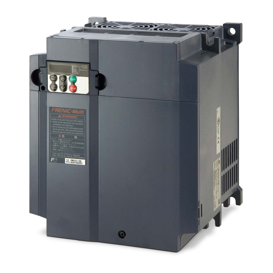
Page 21: External View And Terminal Blocks
1.2 External View and Terminal Blocks (1) Outside and inside views Figure 1.2 Outside and Inside Views of Inverters (FRN020E1S-2U) (2) Warning plates and label Figure 1.3 Warning Plate and Sub Nameplate (3) Terminal block location (a) FRN001E1S-2U (b) FRN020E1S-2U Figure 1.4 Terminal Blocks... -
Page 22: Transportation
1.3 Transportation • When carrying an inverter, always support its bottom at the right and left sides with both hands. Do not hold covers or individual parts only. • Avoid applying excessively strong force to the terminal block covers as they are made of plastic and are easily broken. -
Page 23: Chapter 2 Mounting And Wiring Of The Inverter
Chapter 2 MOUNTING AND WIRING OF THE INVERTER 2.1 Operating Environment Install the inverter in an environment that satisfies the requirements listed in Table 2.1. Table 2.1 Environmental Requirements Table 2.2 Output Current Derating Factor in Relation to Altitude Item Specifications Output current Altitude... - Page 24 When mounting two or more inverters Horizontal layout is recommended when two or more inverters are to be installed in the same unit or panel. If it is necessary to mount the inverters vertically, install a partition plate or the like between the inverters so that any heat radiating from an inverter will not affect the one/s above.
- Page 25 Mount the inverter vertically to the mounting surface and fix it securely with four screws or bolts so that the logo "FRENIC-Multi" can be seen from the front. Do not mount the inverter upside down or horizontally. Doing so will reduce the heat dissipation efficiency of the inverter and cause the overheat protection function to operate, so the inverter will not run.
-
Page 26: Wiring
2.3 Wiring Follow the procedure below. (In the following description, the inverter has already been installed.) 2.3.1 Removing and mounting the terminal cover and the main circuit terminal block cover (1) For inverters with a capacity of 5HP or below To remove the terminal cover, put your finger in the dimple of the terminal cover (labeled "PULL"), and then pull it up toward you. - Page 27 (2) For inverters with a capacity of 7.5 and 10 HP To remove the terminal cover, first loosen the terminal cover fixing screw on it, and put your finger in the dimple of the terminal cover (labeled "PULL"), and then pull it up toward you. To remove the main circuit terminal block cover, put your thumbs on the handles of the main circuit terminal block cover, and push it up while supporting it with your fingers.
- Page 28 (3) For inverters with a capacity of 15 and 20 HP To remove the terminal cover, first loosen the terminal cover fixing screw on it, and put your finger in the dimple of the terminal cover (labeled "PULL"), and then pull it up toward you. To remove the main circuit terminal block cover, hold the handles on the both sides of the main circuit terminal block cover, and pull it up.
-
Page 29: Terminal Arrangement Diagram And Screw Specifications
2.3.2 Terminal arrangement diagram and screw specifications The table below shows the main circuit screw sizes, tightening torque and terminal arrangements. Note that the terminal arrangements differ according to the inverter types. Two terminals designed for grounding shown as the symbol, G in Figures A to E make no distinction between a power supply source (a primary circuit) and a motor (a secondary circuit). - Page 30 Figure F (Note 1) Filter output (Note 2) (Note 1) Terminal screw type is listed in the table below. Inverter type Screw type FRN007E1E-2U Cross FRN010E1E-2U FRN015E1E-2U Hxagon FRN020E1E-2U FRN007E1E-4U Flat FRN010E1E-4U FRN015E1E-4U Cross FRN020E1E-4U (Note 2) Cables of EMC filter output are already connected to inverter input by factory default.
- Page 31 (2) The control circuit terminals (common to all models) Screw size: M3 Tightening torque: 4.4 to 5.3 (lb-in) (0.5 to 0.6 (N·m)) Table 2.5 Control Circuit Terminal Block Dimension of openings in the control circuit terminals for ferrule Wire strip length (for Europe type terminal block)* Screwdriver type Allowable wire size...
-
Page 32: Recommended Wire Sizes
2.3.3 Recommended wire sizes Table 2.7 lists the recommended wire sizes. The recommended wire sizes for the main circuits are examples of using HIV single wire for 75 C (167 F) at an ambient temperature of 50 C (122 F). Table 2.7 Recommended Wire Sizes Recommended wire size AWG(mm Main circuits... -
Page 33: Wiring Precautions
2.3.4 Wiring precautions Follow the rules below when performing wiring for the inverter. (1) Make sure that the power supply voltage is within the rated voltage range specified on the nameplate. (2) Be sure to connect the three-phase power wires to the main circuit power input terminals L1/R, L2/S and L3/T, or connect the single-phase power wires to the main circuit power input terminals L1/L and L2/N of the inverter. - Page 34 Follow the procedure below for wiring and configuration of the inverter. Figure 2.9 illustrates the wiring procedure with peripheral equipment. Wiring procedure Grounding terminals ( G) Inverter output terminals (U, V, W, and DC reactor connection terminals (P1 and P(+)) * DC braking resistor connection terminals (P(+), DB) * DC link bus terminals (P(+) and N(-)) * Main circuit power input terminals (L1/R, L2/S and L3/T, or L1/L and L2/N)
- Page 35 Grounding terminals ( G) Be sure to ground either of the two grounding terminals for safety and noise reduction. The inverter is designed to use with a safety grounding to avoid electric shock, fire and other disasters. Grounding terminals should be grounded as follows: 1) Ground the inverter in compliance with the national or local electric code.
- Page 36 Driving 460 V class series motor • If a thermal relay is installed in the path between the inverter and the motor to protect the motor from overheating, the thermal relay may malfunction even with a wiring length shorter than 164ft (50 m). In this situation, add an output circuit filter (option) or lower the carrier frequency (Function code F26).
- Page 37 DC link bus terminals, P (+) and N (-) These are provided for the DC link bus powered system. Connect these terminals with terminals P(+) and N (-) of other inverters. Consult your Fuji Electric representative if these terminals are to be used. 2-15...
-
Page 38: Wiring For Control Circuit Terminals
Main circuit power input terminals, L1/R, L2/S, and L3/T (three-phase input), or L1/L and L2/N (single-phase input) 1) For safety, make sure that the molded case circuit breaker (MCCB) or magnetic contactor (MC) is turned off before wiring the main circuit power input terminals. 2) Connect the main circuit power supply wires (L1/R, L2/S and L3/T for three-phase input, or L1/L and L2/N for single-phase input) to the input terminals of the inverter via an MCCB or residual-current-operated protective device (RCD)/a ground fault circuit interrupter (GFCI)*, and... - Page 39 Table 2.9 Symbols, Names and Functions of the Control Circuit Terminals Symbol Name Functions [13] Power Power supply (+10 VDC) for frequency command potentiometer supply (Potentiometer: 1 to 5k ) for the The potentiometer of 1/2 W rating or more should be connected. potentio- meter [12]...
- Page 40 Table 2.9 Symbols, Names and Functions of the Control Circuit Terminals (Continued) Symbol Name Functions - Since low level analog signals are handled, these signals are especially susceptible to the external noise effects. Route the wiring as short as possible (within 66ft (20 m)) and use shielded wires.
- Page 41 Table 2.9 Symbols, Names and Functions of the Control Circuit Terminals (Continued) Symbol Name Functions Connects to PLC output signal power supply. [PLC] (Rated voltage: +24 VDC (Maximum 50 mA DC): Allowable range: +22 to signal +27 VDC) power This terminal also supplies a power to the circuitry connected to the transistor output terminals [Y1] and [Y2].
- Page 42 Table 2.9 Symbols, Names and Functions of the Control Circuit Terminals (Continued) Name Functions Symbol [FM] Analog The monitor signal for analog DC voltage (0 to +10 V) is output. You can monitor select FMA function with slide switch SW6 on the interface PCB, and change the data of the function code F29.
- Page 43 Table 2.9 Symbols, Names and Functions of the Control Circuit Terminals (Continued) Symbol Name Functions [Y1] Transistor (1) Various signals such as inverter running, speed/freq. arrival and output 1 overload early warning can be assigned to any terminals, [Y1] and [Y2] by setting function code E20 and E21.
- Page 44 (such as the terminal block of the main circuit). • The RJ-45 connector pin assignment on the FRENIC-Multi series is different from that on the FVR-E11S series. Do not connect to the keypad of the FVR-E11S series of inverter.
-
Page 45: Setting Up The Slide Switches
2.3.7 Setting up the slide switches Before changing the switches, turn OFF the power and wait more than five minutes. Make sure that the LED monitor is turned OFF. Further, make sure, using a circuit tester or a similar instrument, that the DC link bus voltage between the terminals P (+) and N (-) has dropped below the safe voltage (+25 VDC). - Page 46 Figure 2.22 shows the location of slide switches for the input/output terminal configuration. Switching example Factory default SW1* SINK Factory default SOURCE Figure 2.22 Location of the Slide Switches 2-24...
-
Page 47: Mounting And Connecting A Keypad
2.4 Mounting and Connecting a Keypad 2.4.1 Mounting style and parts needed for connection (1) Mounting style You can mount a keypad in any style described below. Mounting a keypad on the panel wall (Refer to Figure 2.23.) Installing a keypad at a remote site (e.g. for operation on hand) (Refer to Figure 2.24.) Figure 2.23 Mounting Keypad on the Panel Wall Figure 2.24 Installing Keypad at a Remote Site (e.g. -
Page 48: Mounting/Installing Steps
(2) Parts needed for connection To mount/install a keypad on a place other than an inverter, parts listed below are needed. Parts name Model Remarks Extension cable (Note) CB-5S, CB-3S and CB-1S 3 cables available in length of 16ft (5m), 9.8ft (3m), and 3.3ft (1m). - Page 49 Make a cut-out on the panel wall. For details, refer to Chapter 8, Section 8.4.2 "Standard keypad." To mount the keypad on the panel, fix it firmly using a pair of M3 screws put through the taps shown below. (Figure 2.27.) (Tightening torque: 6.2 Ib-in (0.7 N m)) Figure 2.27 Mounting a Keypad on the Panel Wall Connect an extension cable (CB-5S, CB-3S or CB-1S) or off-the-shelf straight LAN cable...
-
Page 50: Cautions Relating To Harmonic Component, Noise, And Leakage Current
2.5 Cautions Relating to Harmonic Component, Noise, and Leakage Current (1) Harmonic component Input current to an inverter includes a harmonic component, which may affect other loads and power factor correcting capacitors that are connected to the same power supply as the inverter. If the harmonic component causes any problems, connect a DC reactor (option) to the inverter. -
Page 51: Chapter 3 Operation Using The Keypad
Chapter 3 OPERATION USING THE KEYPAD 3.1 LED Monitor, Keys and LED Indicators on the Keypad 7-segment LED As shown at the right, the keypad monitor consists of a four-digit LED monitor, indicators six keys, and five LED indicators. The keypad allows you to run and stop the motor, monitor running status, and switch to the menu mode. -
Page 52: Overview Of Operation Modes
Hz and kW light. Simultaneous keying Simultaneous keying means pressing two keys at the same time. The FRENIC-Multi supports simultaneous keying as listed below. The simultaneous keying operation is expressed by a "+" letter between the keys throughout this manual. - Page 53 Figure 3.1 shows the status transition of the inverter between these three operation modes. (*1) The speed monitor allows you to select the desired one from the seven speed monitor items by using function code E48. (*2) Applicable only when PID control is active (J01 = 1, 2 or 3). (*3) The Timer screen appears only when the timer operation is enabled with function code C21.
-
Page 54: Running Mode
3.3 Running Mode When the inverter is turned ON, it automatically enters Running mode in which you can: (1) Monitor the running status (e.g., output frequency and output current), (2) Configure the reference frequency and other settings, (3) Run/stop the motor, and (4) Jog (inch) the motor. - Page 55 Table 3.3 Monitoring Items (Continued) Display sample on LED indicator Function Monitor items Unit Meaning of displayed value the LED : ON, : OFF code E43 monitor * 1 PID command PID command/feedback amount * 3 , * 4 transformed to that of virtual physical value of the object to be controlled (e.g.
-
Page 56: Setting Up Frequency And Pid Commands
3.3.2 Setting up frequency and PID commands You can set up the desired frequency and PID commands by using keys on the keypad. It is also possible to set up the frequency command as load shaft speed, motor speed etc. by setting function code E48. - Page 57 (frequency command) with keys; if it is set to any other, you can access the PID process command with those keys. Refer to the FRENIC-Multi User's Manual for the details of the PID control. Setting the PID process command with the keys (1) Set function code J02 to "0:...
- Page 58 Setting up the frequency command with keys under PID process control When function code F01 is set to "0" ( keys on keypad) and frequency command 1 is selected as a manual speed command (when disabling the frequency setting command via communications link or multi-frequency command), switching the LED monitor to the speed monitor in Running mode enables you to modify the frequency command with the keys.
- Page 59 LED monitor is set to the speed monitor (E43 = 0), the item accessible is the primary frequency command; if it is set to any other data, it is the PID dancer position command. Refer to the FRENIC-Multi User's Manual for the details of the PID control. Setting the PID dancer position command with the keys (1) Set function code J02 to "0:...
- Page 60 Setting up the primary frequency command with keys under PID dancer control When function code F01 is set to "0" ( keys on keypad) and frequency command 1 is selected as a primary frequency command (when disabling the frequency setting command via communications link and multi-frequency command), switching the LED monitor to the speed monitor in Running mode enables you to modify the frequency command with the keys.
-
Page 61: Running/Stopping The Motor
3.3.3 Running/stopping the motor By factory default, pressing the key starts running the motor in the forward direction and pressing the key decelerates the motor to stop. The key is enabled only in Running mode. The motor rotational direction can be selected by changing the setting of function code F02. - Page 62 Table 3.9 Menus Available in Programming Mode Refer monitor Menu # Menu Main functions shows: Displays only basic function codes to customize Section "Quick Setup" the inverter operation. 3.4.1 F codes (Fundamental functions) E codes (Extension terminal functions) C codes (Control functions) Selecting each of P codes...
-
Page 63: Setting Up Basic Function Codes Quickly -- Menu #0 "Quick Setup
The predefined set of function codes that are subject to quick setup are held in the inverter. Listed below are the function codes (including those not subject to quick setup) available on the FRENIC-Multi. Table 3.11 Function Codes Available on FRENIC-Multi Function code Function codes... - Page 64 Figure 3.2 shows the menu transition in Menu #0 "Quick Setup." Figure 3.2 Menu Transition in Menu #0 "Quick Setup" Basic key operation This section gives a description of the basic key operation, following the example of the function code data changing procedure shown in Figure 3.3. This example shows you how to change function code F01 data from the factory default "...
-
Page 65: Setting Up Function Codes -- Menu #1 "Data Setting
(5) Change the function code data using the keys. (In this example, press the two times to change data to .) (6) Press the key to establish the function code data. appears and the data will be saved in the memory inside the inverter. The display will return to the function code list, then move to the next function code. -
Page 66: Checking Changed Function Codes -- Menu #2 "Data Checking
3.4.3 Checking changed function codes -- Menu #2 "Data Checking" -- Menu #2 "Data Checking" in Programming mode allows you to check function codes that have been changed. Only the function codes whose data has been changed from the factory defaults are displayed on the LED monitor. - Page 67 Basic key operation To monitor the running status on the drive monitor, set function code E52 to "2" (Full-menu mode) beforehand. (1) Turn the inverter ON. It automatically enters Running mode. In that mode, press the key to switch to Programming mode. The function selection menu appears. (2) Use the keys to display "Drive Monitoring"...
- Page 68 Displaying running status To display the running status in hexadecimal format, each state has been assigned to bits 0 to 15 as listed in Table 3.13. Table 3.14 shows the relationship between each of the status assignments and the LED monitor display. Table 3.15 gives the conversion table from 4-bit binary to hexadecimal. Table 3.13 Running Status Bit Assignment Notation Content...
-
Page 69: Checking I/O Signal Status -- Menu #4 "I/O Checking
3.4.5 Checking I/O signal status -- Menu #4 "I/O Checking" -- Using Menu #4 "I/O Checking" displays the I/O status of external signals including digital and analog I/O signals without using a measuring instrument. Table 3.16 lists check items available. The menu transition in Menu #4 "I/O Checking"... - Page 70 Basic key operation To check the status of the I/O signals, set function code E52 to "2" (Full-menu mode) beforehand. (1) Turn the inverter ON. It automatically enters Running mode. In that mode, press the key to switch to Programming mode. The function selection menu appears. (2) Use the keys to display "I/O Checking"...
- Page 71 "0." Allocated bit data is displayed on the LED monitor as four hexadecimal digits ( each). With the FRENIC-Multi, digital input terminals [FWD] and [REV] are assigned to bit 0 and bit 1, respectively. Terminals [X1] through [X5] are assigned to bits 2 through 6. The bit is set to "1" when the corresponding input terminal is short-circuited (ON), and is set to "0"...
- Page 72 Table 3.18 Segment Display for I/O Signal Status in Hexadecimal Format LED No. LED4 LED3 LED2 LED1 Input (RST)* (XR)* (XF)* X1 REV FWD terminal Output terminal A/B/C Binary Hexa- decimal on the LED monitor – No corresponding control circuit terminal exists. * (XF), (XR), and (RST) are assigned for communication.
-
Page 73: Reading Maintenance Information -- Menu #5 "Maintenance Information
3.4.6 Reading maintenance information -- Menu #5 "Maintenance Information" -- Menu #5 "Maintenance Information" contains information necessary for performing maintenance on the inverter. The menu transition in Menu #5 "Maintenance information" is as same as its of in Menu #3 "Drive Monitoring." Basic key operation To view the maintenance information, set function code E52 to "2"... - Page 74 Table 3.20 Display Items for Maintenance Information (Continued) Monitor Item Description shows: Number of Shows the content of the cumulative counter of times the inverter is startups started up (i.e., the number of run commands issued). 1.000 indicates 1000 times. When any number from 0.001 to 9.999 is displayed, the counter increases by 0.001 per startup, and when any number from 10.00 to 65.53 is counted, the counter increases by 0.01 every 10 startups.
-
Page 75: Reading Alarm Information -- Menu #6 "Alarm Information
3.4.7 Reading alarm information -- Menu #6 "Alarm Information" -- Menu #6 "Alarm Information" shows the causes of the past 4 alarms in alarm code. Further, it is also possible to display alarm information that indicates the status of the inverter when the alarm occurred. - Page 76 Basic key operation To view the alarm information, set function code E52 to "2" (Full-menu mode) beforehand. (1) Turn the inverter ON. It automatically enters Running mode. In that mode, press the key to switch to Programming mode. The function selection menu appears. (2) Use the keys to display "Alarm Information"...
-
Page 77: Alarm Mode
Table 3.21 Alarm Information Displayed (Continued) LED monitor Item displayed Description shows: (item No.) Shows the temperature of the heat sink. Max. temperature of heat sink Unit: ºC Terminal I/O signal status (displayed with the ON/OFF of LED segments) Shows the ON/OFF status of the digital I/O terminals. Terminal input signal status Refer to "... - Page 78 Displaying the status of inverter at the time of alarm When the alarm code is displayed, you may check various running status information (output frequency and output current, etc.) by pressing the key. The item number and data for each running information will be displayed alternately.
-
Page 79: Chapter 4 Running The Motor
Chapter 4 RUNNING THE MOTOR 4.1 Running the Motor for a Test 4.1.1 Inspection and preparation prior to powering on Check the following prior to powering on. (1) Check if connection is correct. Especially check if the power wires are connected to the inverter input terminals L1/R, L2/S and L3/T or L1/L and L2/N, and output terminals U, V and W respectively and that the grounding wires are connected to the ground electrodes correctly. -
Page 80: Preparation Before Running The Motor
4.1.3 Preparation before running the motor for a test--Setting function code data Before running the motor, set function code data specified in Table 4.1 to the motor ratings and your system design values. For the motor, check the rated values printed on the nameplate of the motor. For your system design values, ask system designers about them. - Page 81 2) Selection of tuning process Check the situation of the machine system and choose between "Tuning while the motor is stopped (P04 or A18 = 1)" and "Tuning while the motor is running (P04 or A18 = 2)." In the case of "Tuning while the motor is running (P04 or A18 = 2),"...
-
Page 82: Test Run
4.1.4 Test run If the user specifies the function codes wrongly or without completely understanding this Instruction Manual and the FRENIC-Multi User's Manual, the motor may rotate with a torque or at a speed not permitted for the machine. Accident or injury may result. -
Page 83: Operation
------------------------------------------------ Test Run Procedure ------------------------------------------------- (1) Turn the power ON and check that the reference frequency Hz is blinking on the LED monitor. (2) Set a low reference frequency such as 5 Hz, using keys. (Check that the frequency is blinking on the LED monitor.) (3) Press the key to start running the motor in the forward direction. -
Page 84: Chapter 5 Function Codes
Chapter 5 FUNCTION CODES 5.1 Function Code Tables The following tables list the function codes available for the FRENIC-Multi series of inverters. F codes: Fundamental Functions Change Incre- Data Default Refer to Name Data setting range Code Unit when ment... - Page 85 (F codes continued) Change Refer Incre- Data Default Name Data setting range Code Unit when ment copying setting running page: Motor Sound (Carrier frequency) 0.75 to 15 5-34 (Tone) 0: Level 0 (Inactive) 1: Level 1 2: Level 2 3: Level 3 ( FMA ) F29 Analog Output [FM] 0: Output in voltage (0 to 10 VDC)
- Page 86 E codes: Extension Terminal Functions Change Refer Incre- Data Default Name Data setting range Code Unit when ment copying setting running page: E01 Terminal [X1] Function Selecting function code data assigns the corresponding function to 5-40 terminals [X1] to [X5] as listed below. ( SS1 ) E02 Terminal [X2] Function (1000): Select multi-frequency...
- Page 87 (E codes continued) Change Refer Incre- Data Default Name Data setting range Code Unit when ment copying setting running page: E20 Terminal [Y1] Function Selecting function code data assigns the corresponding function to 5-48 terminals [Y1], [Y2], and [30A/B/C] as listed below. ( RUN ) E21 Terminal [Y2] Function (1000): Inverter running...
- Page 88 (E codes continued) Change Refer Incre- Data Default Name Data setting range Code Unit when ment copying setting running page: E40 PID Display Coefficient A -999 to 0.00 to 9990 *1 0.01 E41 PID Display Coefficient B -999 to 0.00 to 9990 *1 0.01 0.00 E42 LED Display Filter...
- Page 89 (E codes continued) Change Refer Incre- Data Default Name Data setting range Code Unit when ment copying setting running page: E98 Terminal [FWD] Function Selecting function code data assigns the corresponding function to 5-40 terminals [FWD] and [REV] as listed below. ( SS1 ) E99 Terminal [REV] Function (1000): Select multi-frequency...
- Page 90 C codes: Control Functions Change Refer Incre- Data Default Name Data setting range Code Unit when ment copying setting running page: C01 Jump Frequency 1 0.0 to 400.0 (Hysteresis width) 0.0 to 30.0 C05 Multi-Frequency 0.00 to 400.00 *1 0.01 0.00 0.00 0.00...
- Page 91 P codes: Motor 1 Parameters Change Incre- Data Default Refer to Name Data setting range Code Unit when ment copying setting page: running Motor 1 (No. of poles) 2 to 22 poles 5-56 (Rated capacity) 0.01 to 30.00 (where, P99 data is 0, 3, or 4.) 0.01 0.01 to 30.00 (where, P99 data is 1.) 0.01...
- Page 92 H codes: High Performance Functions Change Refer Incre- Data Default Name Data setting range Code Unit when ment copying setting running page: H03 Data Initialization 0: Disable initialization 5-58 Initialize all function code data to the factory defaults 2: Initialize motor 1 parameters 3: Initialize motor 2 parameters H04 Auto-reset (Times)
- Page 93 (H codes continued) Change Incre- Data Default Refer to Name Data setting range Code Unit when ment copying setting page: running ACC/DEC Time 0.00 to 3600 0.01 6.00 (Jogging operation) *ACC time and DEC time are common. Deceleration Time for Forced Stop 0.00 to 3600 0.01 6.00...
- Page 94 (A codes continued) Change Incre- Data Default Refer to Name Data setting range Code Unit when ment copying setting page: running A05 Torque Boost 2 0.0 to 20.0 (percentage with respect to "A03: Rated Voltage at Base Frequency 2") Note: This setting takes effect when A13 = 0, 1, 3, or 4. Electronic Thermal Overload Protection 1: For a general-purpose motor with shaft-driven cooling fan for Motor 2...
- Page 95 J codes: Application Functions Change Refer Incre- Data Default Name Data setting range Code Unit when ment copying setting running page: PID Control (Mode selection) 0: Disable 1: Enable (Process control, normal operation) 2: Enable (Process control, inverse operation) 3: Enable (Dancer control) (Remote command SV) 0: UP/DOWN keys on keypad 1: PID command 1...
- Page 96 (J codes continued) Change Refer Incre- Data Default Name Data setting range Code Unit when ment copying setting running page: J73 Positioning Control (Start timer) *5 0.0 to 1000.0 (Start point; upper digits) *5 -999 to 999 (Start point; lower digits) *5 [P], 0 to 9999 *7 (Preset point;...
- Page 97 y codes: Link Functions Change Incre- Data Default Refer to Name Data setting range Code Unit when ment copying setting page: running RS-485 Communication (Standard) 1 to 255 (Station address) (Communications error processing) 0: Immediately trip with alarm Trip with alarm after running for the period specified by timer y03 Retry during the period specified by timer y03.
- Page 98 Table 5.1 (1) Factory Defaults According to Inverter Capacity Restart mode after Fuji's standard Rated capacity of momentary power Nominal Power torque boost motor failure applied supply Inverter type (HP) (Restart time) motor voltage (HP) F09/A05 P02/A16 FRNF12E1 -2U 0.12 FRNF25E1 -2U 0.25 FRNF50E1 -2U...
- Page 99 Table 5.1 (2) Factory Defaults According to Inverter Capacity Rated current of HP standard motor Nominal Power applied Inverter type supply motor voltage F11/E34/E37/A07 (HP) FRNF12E1 -2U 0.68 FRNF25E1 -2U FRNF50E1 -2U FRN001E1 -2U FRN002E1 -2U Three- phase FRN003E1 -2U 230 V 12.6 FRN005E1 -2U...
- Page 100 Changing, validating, and saving function code data when the inverter is running Function codes are indicated by the following based on whether they can be changed or not when the inverter is running: Change when Notation Validating and saving function code data running Possible If the data of the codes marked with Y* is changed with...
-
Page 101: Overview Of Function Codes
5.2 Overview of Function Codes This section provides an overview of the function codes frequently used for the FRENIC-Multi series of inverter. For details about the function codes given below and other function codes not given below, refer to the FRENIC-Multi User’s Manual, Chapter 9 "FUNCTION CODES" and the RS-485 Communications User's Manual. - Page 102 Data for Function F01, C30 Enable the current input to terminal [C1] (C1 function) (+4 to +20 mA DC, maximum frequency obtained at +20 mA DC). Enable the sum of voltage (0 to +10 VDC) and current inputs (+4 to +20 mA DC) given to terminals [12] and [C1] (C1 function), respectively.
- Page 103 • In addition to the run command sources described above, higher priority command sources including communications link are provided. For details, refer to the FRENIC-Multi User's Manual. Maximum Frequency 1 F03 specifies the maximum frequency to limit a reference frequency. Specifying the maximum frequency exceeding the rating of the equipment driven by the inverter may cause damage or a dangerous situation.
- Page 104 Base Frequency 1 Rated Voltage at Base Frequency 1 Maximum Output Voltage 1 H50, H51 Non-linear V/f Pattern 1 (Frequency and Voltage) H52, H53 Non-linear V/f Pattern 2 (Frequency and Voltage) These function codes specify the base frequency and the voltage at the base frequency essentially required for running the motor properly.
- Page 105 Examples: Normal (linear) V/f pattern V/f pattern with two non-linear points Acceleration Time 1 Deceleration Time 1 Acceleration Time 2 Deceleration Time 2 F07 specifies the acceleration time, the length of time the frequency increases from 0 Hz to the maximum frequency. F08 specifies the deceleration time, the length of time the frequency decreases from the maximum frequency down to 0 Hz.
- Page 106 V/f pattern (factory default). V/f characteristics The FRENIC-Multi series of inverters offers a variety of V/f patterns and torque boosts, which include V/f patterns suitable for variable torque load such as general fans and pumps or for special pump load requiring high starting torque.
- Page 107 When the variable torque V/f pattern is selected (F37 = 0 or 3), the output voltage may be low and insufficient voltage output may result in less output torque of the motor at a low frequency zone, depending on some characteristics of the motor itself and load.
- Page 108 • Auto torque boost This function automatically optimizes the output voltage to fit the motor with its load. Under light load, auto torque boost decreases the output voltage to prevent the motor from over-excitation. Under heavy load, it increases the output voltage to increase output torque of the motor.
- Page 109 The figure below shows operating characteristics of the electronic thermal overload protection when F10 = 1. The characteristic factors 1 through 3 as well as their corresponding switching frequencies f and f vary with the characteristics of the motor. The tables below list the factors of the motor selected by P99 (Motor 1 Selection).
- Page 110 Thermal time constant (F12) F12 specifies the thermal time constant of the motor. If the current of 150% of the overload detection level specified by F11 flows for the time specified by F12, the electronic thermal overload protection becomes activated to detect the motor overload. The thermal time constant for general-purpose motors including Fuji motors is approx.
- Page 111 Restart Mode after Momentary Power Failure Restart Mode after Momentary Power Failure, Restart time Restart Mode after Momentary Power Failure, Frequency fall rate Restart Mode after Momentary Power Failure, Allowable momentary power failure time F14 specifies the action to be taken by the inverter such as trip and restart in the event of a momentary power failure.
- Page 112 Restart mode after momentary power failure (Basic operation) The inverter recognizes a momentary power failure upon detecting the condition that DC link bus voltage goes below the undervoltage detection level, while the inverter is running. If the load of the motor is light and the duration of the momentary power failure is extremely short, the voltage drop may not be great enough for a momentary power failure to be recognized, and the motor may continue to run uninterrupted.
- Page 113 During a momentary power failure, the motor slows down. After power is restored, the inverter restarts at the frequency just before the momentary power failure. Then, the current limiting function works and the output frequency of the inverter automatically decreases. When the output frequency matches the motor speed, the motor accelerates up to the original output frequency.
- Page 114 Follow data specified by H14 Follow the setting of the PI controller in the current limiter (of the current limit control block shown in FRENIC-Multi User's Manual, Chapter 4, Section 4.4, Figure 4.3.1 "). (The PI constant is prefixed inside the inverter.) he frequency fall rate is too high, regeneration may take place at the moment the motor rotation matches the inverter output frequency, causing an overvoltage trip.
- Page 115 Bias (Frequency command 1) Bias (for Frequency 1) (Bias base point) C32, C34 Analog Input Adjustment for [12] (Gain, Gain base point) C37, C39 Analog Input Adjustment [C1] (Gain, Gain base point) C42, C44 Analog Input Adjustment [V2] (Gain, Gain base point) When any analog input for frequency command 1 (F01) is used, it is possible to define the relationship between the analog input and the reference frequency by multiplying the gain and adding the bias specified by F18.
- Page 116 (Point A) To set the reference frequency to 0 Hz for an analog input being at 1 V, set the bias to 0% (F18 = 0). Since 1 V is the bias base point and it is equal to 10% of 10 V (full scale), set the bias base point to 10% (C50 = 10).
- Page 117 In general, specify data of function code F20 at a value close to the rated slip frequency of motor. If you set it at an extremely high value, control may become unstable and an overvoltage alarm may result in some cases. The DC brake function of the inverter does not provide any holding mechanism.
- Page 118 Specifying a too low carrier frequency will cause the output current waveform to have a large amount of ripples. As a result, the motor loss increases, causing the motor temperature to rise. Furthermore, the large amount of ripples tends to cause a current limiting alarm.
- Page 119 Function (F31) F31 specifies what is output to analog output terminal [FM]. Data for Function Meter scale [FM] output (Monitor the following) (Full scale at 100%) Output frequency of the inverter Output frequency (before slip Maximum frequency (F03/A01) (Equivalent to the motor compensation) synchronous speed) Output frequency...
- Page 120 The torque limiter and current limiter are very similar function each other. If both are activated concurrently, they may conflict each other and cause a hunting in the system. Avoid concurrent activation of these limiters. Control Mode Selection 1 Slip Compensation 1 (Operating conditions) F42 specifies the control mode of the inverter to control a motor.
- Page 121 In the slip compensation and dynamic torque vector control, the inverter uses the motor parameters to control its speed. Therefore, the following conditions should be satisfied; if not, the inverter may not get the proper performance from the motor. • A single motor should be controlled. (It is difficult to apply this control to a group motor driving system.) •...
- Page 122 The table below lists the discharging capability and allowable average loss of the braking resistor. These values depend upon the inverter and braking resistor models. External Braking Resistors Standard models The thermal sensor relay mounted on the braking resistor acts as a thermal protector of the motor for overheat, so assign an "Enable external alarm trip"...
- Page 123 10% ED models Continuous braking Intermittent braking Braking resistor (100% braking torque) (Period: Less than 100 s) Power Resistance supply Inverter type Discharging Braking Allowable Duty voltage capacity Type Qty. time average loss (%ED) (kW) (kWs) 1000 FRNF12E1 -2U FRNF25E1 -2U DB0.75-2C 0.075 FRNF50E1 -2U...
- Page 124 Function code data Terminal commands assigned Symbol Active ON Active OFF 1000 1001 Select multi-frequency (0 to 15 steps) 1002 1003 1004 Select ACC/DEC time 1006 Enable 3-wire operation 1007 Coast to a stop 1008 Reset alarm 1009 Enable external alarm trip 1010 Ready for jogging Hz2/Hz1...
- Page 125 SS1, SS2, SS4 and SS8. In the "Selected frequency" column, "Other than multi-frequency" represents the reference frequency sourced by frequency command 1 (F01), frequency command 2 (C30), or others. For details, refer to the block diagram in FRENIC-Multi User's Manual, Chapter 4, Section 4.2 "Drive Frequency Command Block."...
- Page 126 Enable 3-wire operation -- HLD (Function code data = 6) Turning this terminal command ON self-holds the forward FWD or reverse REV run command issued with it, to enable 3-wire inverter operation. Short-circuiting the terminals between HLD and [CM] (i.e., when HLD is ON) self-holds the first FWD or REV command at its leading edge.
- Page 127 Ready for jogging -- JOG (Function code data = 10) This terminal command is used to jog or inch the motor for positioning a work piece. Turning this command ON makes the inverter ready for jogging. Simultaneous keying keys on the keypad is functionally equivalent to this command; however, it is restricted by the run command source as listed below.
- Page 128 Select motor 2 / motor 1 -- M2/M1 (Function code data = 12) Turning this terminal command ON switches from motor 1 to motor 2. Switching is possible only when the inverter is stopped. Upon completion of switching, the digital terminal output "Switched to motor 2"...
- Page 129 Motor 2 imposes functional restrictions on the following function codes. Confirm the settings of those function codes before use. Related function Functions Restrictions codes Non-linear V/f pattern Disabled. Linear V/f pattern only H50 to H53 Starting frequency Starting frequency holding time not supported. F24 Stop frequency Stop frequency holding time not supported.
- Page 130 The UP/DOWN control is available in two modes--one mode (H61 = 0) in which the initial value of the reference frequency is fixed to "0.00" at the start of the UP/DOWN control and the other mode (H61 = 1) in which the reference frequency applied in the previous UP/DOWN control applies as the initial value.
- Page 131 Enable communications link via RS-485 or field bus (option) -- LE (Function code data = 24) Turning this terminal command ON assigns priorities to frequency commands or run commands received via the RS-485 communications link (H30) or the field bus option (y98). No LE assignment is functionally equivalent to the LE being ON.
- Page 132 The table below lists functions that can be assigned to terminals [Y1], [Y2], and [30A/B/C]. To make the explanations simpler, the examples shown below are all written for the normal logic (Active ON). Function code data Functions assigned Symbol Active ON Active OFF 1000 Inverter running...
- Page 133 Frequency arrival signal -- FAR (Function code data = 1) This output signal comes ON when the difference between the output frequency and reference frequency comes within the frequency arrival hysteresis width specified by E30. (Refer to the description of E30.) Frequency detected -- FDT (Function code data = 2) This output signal comes ON when the output frequency exceeds the frequency detection level specified by E31, and it goes OFF when the output frequency drops below the...
- Page 134 Inverter output limiting with delay -- IOL2 (Function code data = 22) If the inverter enters any output limiting operation such as output torque limiting, output current limiting, automatic deceleration (anti-regenerative control), or overload stop (hit and stop), it automatically activates the stall-free facility and shifts the output frequency. When such an output limiting operation continues for 20 ms or more, this output signal comes ON.
- Page 135 Brake signal -- BRKS (Function code data = 57) This signal outputs a brake control command that releases or activates the brake. Refer to the descriptions of J68 through J72. Alarm output (for any alarm) -- ALM (Function code data = 99) This output signal comes ON if any of the protective functions is activated and the inverter enters Alarm mode.
- Page 136 Coefficient for Constant Feeding Rate Time Coefficient for Speed Indication E39 and E50 specify coefficients for determining the constant feeding rate time, load shaft speed, and line speed, as well as for displaying the output status monitored. Calculation expression Coefficient for speed indication (E50) Constant feeding rate time (min) = Frequency ×...
- Page 137 Terminal [12] Extended Function Terminal [C1] Extended Function (C1 function) Terminal [C1] Extended Function (V2 function) E61, E62, and E63 define the property of terminals [12], [C1] (C1 function), and [C1] (V2 function), respectively. There is no need to set up these terminals if they are to be used for frequency command sources.
- Page 138 Timer Operation C21 enables or disables a timer operation that is triggered by a run command and continues for the timer count previously specified with the keys. The operating procedure for the timer operation is given below. Data for C21 Function Disable timer operation Enable timer operation...
- Page 139 Motor 1 (No. of poles) P01 specifies the number of poles of the motor. Enter the value given on the nameplate of the motor. This setting is used to display the motor speed on the LED monitor (refer to E43). The following expression is used for the conversion.
- Page 140 P10 determines the response time for slip compensation. Basically, there is no need to modify the default setting. If you need to modify it, consult your Fuji Electric representatives. Motor 1 Selection P99 specifies the motor to be used.
- Page 141 For P99, enter the following data according to the motor type. • P99 = 0 (Motor characteristics 0): Fuji standard 8-series motors (Current standard) • P99 = 3 (Motor characteristics 3): Fuji standard 6-series motors (Conventional standard) • P99 = 4 (Other motors): Other manufacturer’s or unknown motors •...
- Page 142 When Fuji standard 8-series motors (P99 = 0) or other motors (P99 = 4 or A39 = 4) are selected, the motor parameters are as listed in the following tables. 230 V class series Motor Rated No-load Rated slip Norminal capacity current current...
- Page 143 H04, H05 Auto-reset (Times and Reset interval) H04 and H05 specify the auto-reset function that makes the inverter automatically attempt to reset the tripped state and restart without issuing an alarm (for any faults) even if any protective function subject to reset is activated and the inverter enters the forced-to-stop state (tripped state).
- Page 144 Cooling Fan ON/OFF Control To prolong the life of the cooling fan and reduce fan noise during running, the cooling fan stops when the temperature inside the inverter drops below a certain level while the inverter stops. However, since frequent switching of the cooling fan shortens its life, the cooling fan is kept running for 10 minutes once it is started.
- Page 145 Acceleration/deceleration time <S-curve acceleration/deceleration (weak): when the frequency change is 10% or more of the maximum frequency> Acceleration or deceleration time (s): (2 5/100 + 90/100+ 2 5/100) (reference acceleration or deceleration time) = 1.1 (reference acceleration or deceleration time) <S-curve acceleration/deceleration (strong): when the frequency change is 20% or more of the maximum frequency>...
- Page 146 H09 and STM terminal command ("Enable auto search for idling motor speed at starting") The combination of H09 data and the STM state determines whether to perform the auto search as listed below. Auto search for idling motor speed at starting Data for H09 For restart after momentary For normal startup...
- Page 147 Deceleration Mode H11 specifies the deceleration mode to be applied when a run command is turned OFF. Data for H11 Function Normal deceleration The inverter decelerates and stops the motor according to deceleration commands specified by H07 (Acceleration/deceleration pattern), F08 (Deceleration time 1), and E11 (Deceleration time 2).
- Page 148 Droop Control In a system in which two or more motors drive single machinery, any speed gap between inverter-driven motors results in some load unbalance between motors. The droop control allows each inverter to drive the motor with the speed droop characteristics for increasing its load, eliminating such kind of load unbalance.
- Page 149 = 2 y98 = 2 y98 = 2 y98 = 3 For details, refer to the FRENIC-Multi User's Manual, Chapter 4 "BLOCK DIAGRAMS FOR CONTROL LOGIC" and the RS-485 Communication User's Manual or the Field Bus Option Instruction Manual. 5-66...
- Page 150 Mock Alarm Clear Alarm Data H45 causes the inverter to generate a mock alarm in order to check whether external sequences function correctly at the time of machine setup. Setting the H45 data to "1" displays mock alarm on the LED monitor and issues alarm output ALM to the digital output terminal specified (see E20, E21 and E27).
- Page 151 Overload Prevention Control H70 specifies the decelerating rate of the output frequency to prevent a trip from occurring due to an overload. This control decreases the output frequency of the inverter before the inverter trips due to a heat sink overheat or inverter overload (with an alarm indication of , respectively).
- Page 152 input phase loss protection, (c) output phase loss protection, and (d) judgment on the life of the DC link bus capacitor, as well as specifying the judgment threshold on the life of the DC link bus capacitor, in a style of combination (Bit 0 to Bit 4). Automatic lowering of carrier frequency (Bit 0) This function should be used for important machinery that requires keeping the inverter running.
- Page 153 Input phase loss protection ( ) (Bit 1) Upon detection of an excessive stress inflicted on the apparatus connected to the main circuit due to phase loss or line-to-line voltage unbalance in the three-phase power supplied to the inverter, this feature stops the inverter and displays an alarm In configurations where only a light load is driven or a DC reactor is connected, phase loss or line-to-line voltage unbalance may not be detected because of the relatively small stress on the apparatus connected to the main circuit.
- Page 154 Conversion table (Decimal to/from binary) Binary Binary Decimal Decimal Bit 4 Bit 3 Bit 2 Bit 1 Bit 0 Bit 4 Bit 3 Bit 2 Bit 1 Bit 0 Overload Stop J63 to J67 (Detection value, Detection level, Mode selection, Operation condition and Timer) When the monitored status index of the load exceeds the detection level specified by J64 for the period specified by J67, the inverter activates the overload stop function according to operation specified by J65.
- Page 155 Mode selection (J65) J65 specifies operation when the load amount exceeds that of one specified by J64. Mode Description Data for J65 Disable The inverter cancels the overload stop function. The inverter decelerate-to-stops the motor by the Decelerate to stop specified deceleration time.
- Page 156 Releasing the Brake The inverter releases the brake (Terminal command BRKS: ON) after checking torque generation of the motor, monitoring whether it applies both the output current and frequency to the motor, which are higher than ones specified for the time long enough. Name Data setting range Function code...
-
Page 157: Chapter 6 Troubleshooting
(1) First, check that the inverter is correctly wired, referring to Chapter 2 Section 2.3.5 "Wiring for main circuit terminals and grounding terminals." (2) Check whether an alarm code is displayed on the LED monitor. If any problems persist after the above recovery procedure, contact your Fuji Electric representative. -
Page 158: If No Alarm Code Appears On The Led Monitor
Checking" and Menu #4 "I/O Checking" using the keypad. active, and the run * Refer to the FRENIC-Multi User's Manual, Chapter 4. command was stopped. Correct any incorrect function code data settings (in H30, y98, etc.) or cancel the higher priority run command. - Page 159 * Refer to the FRENIC-Multi User's Manual, Chapter 4. Correct any incorrect function code data settings (e.g. cancel the higher priority run command). (8) The upper and lower...
- Page 160 * Refer to the FRENIC-Multi User's Manual, Chapter 4. frequency was too low. Correct any incorrect data of function code (e.g. cancel higher priority run commands, etc.).
- Page 161 Possible Causes What to Check and Suggested Measures (9) In the torque control Check whether data of torque limiter related function codes (F40, mode, the output F41, E16 and E17) is correctly configured and the torque limit switching signal TL2/TL1 is correct. frequency does not increase.
- Page 162 Possible Causes What to Check and Suggested Measures (3) Frequency switching or Check whether the relay signal for switching the frequency multi-frequency command is chattering. command was enabled. If the relay has a contact problem, replace the relay. (4) The connection Check whether auto-torque boost or auto-energy saving operation is enabled.
- Page 163 [ 6 ] The motor does not accelerate and decelerate at the set time. Possible Causes What to Check and Suggested Measures (1) The inverter ran the Check the data of function code H07 (Acceleration/deceleration pattern). motor by S-curve or curvilinear pattern.
-
Page 164: Problems With Inverter Settings
[ 7 ] Even if the power recovers after a momentary power failure, the motor does not restart. Possible Causes What to Check and Suggested Measures (1) The data of function Check if an undervoltage trip occurs. code F14 is either "0" or Change the data of function code F14 (Restart mode after "1."... - Page 165 Possible Causes Check and Measures (3) The keypad was not Check whether the keypad is properly connected to the inverter. properly connected to Remove the keypad, put it back, and see whether the problem the inverter. persists. Replace the keypad with another one and check whether the problem persists.
-
Page 166: If An Alarm Code Appears On The Led Monitor
6.3 If an Alarm Code Appears on the LED Monitor Quick reference table of alarm codes Alarm Alarm Name Refer to Name Refer to code code Electronic thermal overload alarm 1 6-17 Electronic thermal overload alarm 2 Instantaneous overcurrent 6-10 Overload 6-17 Memory error... -
Page 167: Overvoltage
Implement noise control measures. For details, refer to "Appendix A" of the FRENIC-Multi User's Manual. Enable the Auto-reset (H04). Connect a surge absorber to the coil or solenoid of the magnetic contactor causing the noise. -
Page 168: Undervoltage
Check if the DC link bus voltage was below the protective level noise. when the alarm occurred. Improve noise control. For details, refer to "Appendix A" of the FRENIC-Multi User's Manual. Enable the Auto-reset (H04). Connect a surge absorber to the coil or solenoid of the magnetic contactor causing the noise. -
Page 169: Input Phase Loss
If the ripple is large, raise the inverter capacity. (5) Single-phase voltage Check the inverter type. was input to the Apply three-phase power. FRENIC-Multi of three-phase input three-phase input cannot be driven by single-phase power supply. inverter instead of three-phase voltage input. -
Page 170: Output Phase Loss
(4) A single-phase motor Single-phase motors cannot used. Note that has been connected. FRENIC-Multi only drives three-phase induction motors. [ 6 ] Heat sink overheat Problem Temperature around heat sink rose. Possible Causes What to Check and Suggested Measures (1) Temperature around the Measure the temperature around the inverter. -
Page 171: Alarm Issued By An External Device
[ 7 ] Alarm issued by an external device Problem External alarm was inputted (THR). (when "Enable external alarm trip" THR is assigned to one of digital input terminals [X1] through [X5], [FWD], and [REV]) Possible Causes What to Check and Suggested Measures (1) An alarm function of the Inspect external equipment operation. -
Page 172: Braking Resistor Overheated
Possible Causes What to Check and Suggested Measures (6) The value set for the Check the data of function codes F09 and A05 and readjust the torque boost (F09 and data so that the motor does not stall even if you set the data to a lower value. -
Page 173: Electronic Thermal Overload Alarm 1
[ 10 ] Electronic thermal overload alarm 1 Electronic thermal overload alarm 2 Problem Electronic thermal protection for motor 1 or motor 2 activated. Possible Causes What to Check and Suggested Measures (1) The characteristics of Check the motor characteristics. electronic thermal did Reconsider the data of function codes (P99, F10 and F12) and not match those of the... -
Page 174: Memory Error
Initialize the function code data by setting H03 to "1," then reset the alarm by pressing the key and check that the alarm goes on. The control PCB (on which the CPU is mounted) is defective. Contact your Fuji Electric representative. 6-18... -
Page 175: Keypad Communications Error
(e.g., correct grounding and routing of control and inverter. main circuit wires). Improve noise control. For details, refer to "Appendix A" of the FRENIC-Multi User's Manual. (3) The keypad Check that alarm does not occur if you connect another malfunctioned. -
Page 176: Operation Protection
[ 17 ] Operation protection Problem You incorrectly operated the inverter. Possible Causes What to Check and Suggested Measures Although a Run command had been inputted from the input (1) The key was terminal or through the communications port, the inverter was pressed when H96 = 1 forced to decelerate to stop. -
Page 177: Communications Error (Option Card)
Possible Causes What to Check and Suggested Measures (4) The rated capacity of the Check whether the rated capacity of the motor is smaller than that motor was significantly of the inverter by three or more orders of class or larger by two or more orders of class. -
Page 178: Data Saving Error During Undervoltage
OFF) back to the original values and then restart the operation. (3) The control circuit failed. Check if occurs each time power is switched ON. The control PCB (on which the CPU is mounted) is defective. Contact your Fuji Electric representative. 6-22... -
Page 179: Hardware Error
(2) The capacity is not set The inverter capacity needs to be modified again. properly on the control Contact your Fuji Electric representative. PCB. (3) An abnormality is found Replacement of any boards with an hazard may be required. -
Page 180: If An Abnormal Pattern Appears On The Led Monitor While No Alarm Codeis Displayed
6.4 If an Abnormal Pattern Appears on the LED Monitor while No Alarm Code is Displayed [ 1 ] – – – – (center bar) appears Problem A center bar (– – – –) has appeared on the LED monitor. Possible Causes What to Check and Suggested Measures (1) Any of PID commands... -
Page 181: Chapter 7 Maintenance And Inspection
Chapter 7 MAINTENANCE AND INSPECTION Perform daily and periodic inspection to avoid trouble and keep reliable operation for a long time. Take care of the following items during work. • Before proceeding to the maintenance and inspection, turn OFF the power and wait more than five minutes. - Page 182 Table 7.1 List of Periodic Inspections (Continued) Check part Check item How to inspect Evaluation criteria 1) Check if the display is clear. 1), 2) 1), 2) Keypad 2) Check if there is missing parts in Visual inspection The display can the characters.
-
Page 183: List Of Periodical Replacement Parts
Each part of the product has its own service life that will vary according to the environmental and operating conditions. It is recommended that the following parts be replaced as specified below. When the replacement is necessary, consult your Fuji Electric representative. Table 7.2 Replacement Parts... -
Page 184: Judgment On Service Life
7.3.1 Judgment on service life (1) Viewing data necessary for judging service life; Measurement procedures Through Menu #5 "Maintenance Information" in Programming mode, you can view on the keypad various data (as a guideline) necessary for judging whether key components such as the DC link bus capacitor, electrolytic capacitors on the printed circuit boards, and cooling fan are approaching their service life. - Page 185 -2 Measuring the capacitance of the DC link bus capacitor (during power-off time under ordinary operating condition) If the measuring method for discharging condition of the DC link bus capacitor during a power-off time under the ordinary operating condition at the end user’s installation is different from the initial measuring method at the time of factory shipment, the capacitance of the DC link bus capacitors can not be measured.
-
Page 186: Measurement Of Electrical Amounts In Main Circuit
Cooling fan Select Menu #5 "Maintenance Information" and check the accumulated run time of the cooling fan. The inverter accumulates hours for which the cooling fan has run. The display is in units of 1000 hours. The accumulated time should be used just a guide since the actual service life will be significantly affected by the temperature and operation environment. - Page 187 Table 7.4 Meters for Measurement of Main Circuit DC link bus Input (primary) side Output (secondary) side voltage (P (+)-N (-)) Voltage Current Voltage Current Ammeter Voltmeter Wattmeter Ammeter Voltmeter Wattmeter DC voltmeter Rectifier or Digital Moving iron Digital AC Digital AC Digital AC Moving coil...
-
Page 188: Insulation Test
A dielectric strength test will cause breakage of the inverter similarly to the Megger test if the test procedure is wrong. When the dielectric strength test is necessary, contact your Fuji Electric representative. -
Page 189: Inquiries About Product And Guarantee
2) However, in cases where the use environment, conditions of use, use frequency and times used, etc., have an effect on product life, this warranty period may not apply. 3) Furthermore, the warranty period for parts restored by Fuji Electric's Service Department is ''6 months from the date that repairs are completed.''... - Page 190 1) In the event that breakdown occurs during the product's warranty period which is the responsibility of Fuji Electric, Fuji Electric will replace or repair the part of the product that has broken down free of charge at the place where the product was purchased or where it was delivered.
- Page 191 [ 3 ] Repair period after production stop, spare parts supply period (holding period) Concerning models (products) which have gone out of production, this company will perform repairs for a period of 7 years after production stop, counting from the month and year when the production stop occurs.
-
Page 192: Chapter 8 Specifications
Chapter 8 SPECIFICATIONS 8.1 Standard Models 8.1.1 Three-phase 230 V class series Standard 4-pole motor Rated capacity is calculated assuming the output rated voltage as 230 V. Output voltage cannot exceed the power supply voltage. Use the inverter at the current enclosed with parentheses ( ) or below when the carrier frequency is set to 4 kHz or above (F26) and the inverter continuously runs at 100% load. -
Page 193: Three-Phase 460 V Class Series
8.1.2 Three-phase 460 V class series Standard 4-pole motor Rated capacity is calculated assuming the output rated voltage as 460 V. Output voltage cannot exceed the power supply voltage. Use the inverter at the current enclosed with parentheses ( ) or below when the carrier frequency is set to 4 kHz or above (F26) and the inverter continuously runs at 100% load. -
Page 194: Single-Phase 230 V Class Series
8.1.3 Single-phase 230 V class series *1 Standard 4-pole motor *2 Rated capacity is calculated by assuming the output rated voltage as 230 V. *3 Output voltage cannot exceed the power supply voltage. *4 Use the inverter at the current enclosed with parentheses ( ) or below when the carrier frequency is set to 4 kHz or above (F26) and the inverter continuously runs at 100% load. -
Page 195: Models Available On Order (Emc Filter Built-In Type)
8.2 Models Available on Order (EMC filter built-in type) 8.2.1 Three-phase 230 V class series Item Specifications Type(FRN_ _ _ E1E-2U) Applicable motor rating (HP) *1 11.2 11.7 22.7 24.9 Weight(lbs(kg)) (0.7) (0.7) (0.8) (0.9) (2.4) (2.4) (2.9) (5.1) (5.3) (10.3) (11.3) Category C2... -
Page 196: Specifications Of Keypad Related
8.3 Specifications of Keypad Related 8.3.1 General specifications of keypad Table 8.1 General Specifications Items Specification Remarks Protective structure Front side: IP40, Back (mounting) side: IP20 Site to be installed In door Ambient temperature -10 C (14 F) to 50 C (122 F) Ambient humidity 5 to 95% RH, no condensation allowed No corrosive gas, no inflammable gas, no dust, and no... -
Page 197: Terminal Specifications
8.4 Terminal Specifications 8.4.1 Terminal functions For details about the main and control circuit terminals, refer to Chapter 2, Section 2.3.5 and Section 2.3.6 (Table 2.9), respectively. 8.4.2 Running the inverter with keypad Ground-fault circuit interrupter (Note 1) When connecting an optional DCR, remove the jumper bar from the terminals [P1] and [P (+)]. (Note 2) Install a recommended MCCB or RCD/GFCI (with overcurrent protection) in the primary circuit of the inverter to protect wiring. -
Page 198: Running The Inverter By Terminal Commands
8.4.3 Running the inverter by terminal commands Ground-fault circuit interrupter (Note 1) When connecting an optional DCR, remove the jumper bar from the terminals [P1] and [P (+)]. (Note 2) Install a recommended MCCB or RCD/GFCI (with overcurrent protection) in the primary circuit of the inverter to protect wiring. -
Page 199: Frn001E1S-2U
8.5 External Dimensions 8.5.1 Standard models Unit: inch(mm) Power supply inch(mm) Dimensions [ Inverter type voltage FRNF12E1S-2U 3.62(92) 0.39(10) Three-phase FRNF25E1S-2U 230 V FRNF50E1S-2U 4.21(107) 0.98(25) FRN001E1S-2U 3.23(82) 5.20(132) 1.97(50) FRNF12E1S-7U 3.62(92) 0.39(10) Single-phase FRNF25E1S-7U 230 V FRNF50E1S-7U 4.21(107) 0.98(25) FRN001E1S-7U 5.00(152) 4.02(102) 1.97(50) inch(mm) -
Page 200: Frn002E1S-2U
Unit: inch(mm) Power supply inch(mm) Dimensions [ Inverter type voltage Three-phase FRN002E1S-2U 230 V FRN003E1S-2U 5.90 3.39 (150) (86) 2.52 Three-phase FRN002E1S-4U (64) 460 V FRN003E1S-4U Single-phase 6.30 3.78 FRN002E1S-7U 230 V (160) (96) Power supply voltage Inverter type Three-phase 230 V FRN005E1S-2U Three-phase 460 V FRN005E1S-4U... -
Page 201: Frn010E1S-2U 6
Unit: inch(mm) Power supply voltage Inverter type FRN007E1S-2U Three-phase 230 V FRN010E1S-2U FRN007E1S-4U Three-phase 460 V FRN010E1S-4U Power supply voltage Inverter type FRN015E1S-2U Three-phase 230 V FRN020E1S-2U FRN015E1S-4U Three-phase 460 V FRN020E1S-4U 8-10... -
Page 202: Models Available On Order (Emc Filter Built-In Type)
8.5.2 Models Available on Order (EMC filter built-in type) Unit: inch(mm) (4-5x6) (4-5x7) 8-11... - Page 203 Unit: inch(mm) 8-12...
- Page 204 Unit: inch(mm) 8-13...
-
Page 205: Standard Keypad
8.5.3 Standard keypad Unit: inch(mm) For remote operation or panel wall-mounting (The keypad rear cover should be mounted.) 8-14... -
Page 206: Protective Functions
8.6 Protective Functions Alarm Name Description monitor output displays [30A/B/C] Overcurrent Stops the inverter output to protect the During protection inverter from an overcurrent resulting from acceleration overload. Short-circuit Stops the inverter output to protect the protection inverter from overcurrent short-circuiting in the output circuit. - Page 207 Alarm Name Description monitor output displays [30A/B/C] Overload Stops the inverter output if the Insulated Gate Bipolar protection Transistor (IGBT) internal temperature calculated from the output current and temperature of inside the inverter is over the preset value. External alarm Places the inverter in alarm-stop state upon receiving digital input signal THR.
- Page 208 Alarm Name Description monitor output displays [30A/B/C] Option Upon detection of an error in the communication between the communications inverter and an optional card, stops the inverter output. error detection Option error When an option card has detected an error, this function stops detection the inverter output.
- Page 209 Alarm Name Description monitor output displays [30A/B/C] Protection Upon detecting a momentary power failure lasting more than 15 —- — against ms, this function stops the inverter output. momentary If restart after momentary power failure is selected, this function power failure invokes a restart process when power has been restored within a predetermined period.
-
Page 210: Chapter 9 List Of Peripheral Equipment And Options
LIST OF PERIPHERAL EQUIPMENT AND OPTIONS The table below lists the main peripheral equipment and options that are connected to the FRENIC-Multi. Use them in accordance with your system requirements. For details, refer to the FRENIC-Multi User's Manual, Chapter 6 "SELECTING PERIPHERAL EQUIPMENT." Name of... - Page 211 Name of peripheral Function and application equipment An MC can be used at both the power input (primary) and output (secondary) Magnetic sides of the inverter. At each side, the MC works as described below. When contactor (MC) inserted in the output circuit of the inverter, an MC can also switch the motor drive power supply between the inverter output and commercial power lines.
- Page 212 In case the inter-phase unbalance factor of the commercial power supply exceeds 3%, you would need to take other measures such as increasing the capacity of the inverter. Consult your Fuji Electric representative. In a DC link bus system (using terminals [P (+)] and [N (-)]), the AC reactor protects the inverter against damage caused by unbalance in current.
- Page 213 Equipped with a liquid crystal display (LCD). Also allows you to copy function code data from one FRENIC-Multi inverter to another. The extension cable connects the RS-485 communications port (standard) Extension cable with a keypad or an RS-485–USB converter.
-
Page 214: Chapter 10 Compliance With Standards
10.1.2 Considerations when using FRENIC-Multi in systems to be certified by UL and cUL If you want to use the FRENIC-Multi series of inverters as a part of UL Standards or CSA Standards (cUL certified) certified product, refer to the related guidelines described on page viii. -
Page 215: Compliance With Emc Standards
10.3 Compliance with EMC Standards 10.3.1 General The CE marking on inverters does not ensure that the entire equipment including our CE-marked products is compliant with the EMC Directive. Therefore, CE marking for the equipment shall be the responsibility of the equipment manufacturer. For this reason, Fuji’s CE mark is indicated under the condition that the product shall be used within equipment meeting all requirements for the relevant Directives. - Page 216 5) If noise from the inverter exceeds the permissible level, enclose the inverter and its peripherals within a metal enclosure as shown in Figure 10.3. GFCI FRENIC-Multi Figure 10.3 Installing the EMC Filter Built-in Type of Inverters into a Metal Enclosure 10-3...
- Page 217 3) If noise from the inverter exceeds the permissible level, enclose the inverter and its peripherals within a metal enclosure as shown in Figure 10.4. GFCI FRENIC-Multi Figure 10.4 Installing the Inverter with an External EMC-compliant Filter (Optional) into a Metal Enclosure 10-4...
-
Page 218: Leakage Current From Emc-Filter Built-In Type Inverters Or Inverters With An External Emc-Complaint Filter (Optional)
10.3.3 Leakage current from EMC-filter built-in type inverters or inverters with an external EMC-complaint filter (optional) Table 10.1 Leakage Current from EMC Filter Built-in Type Inverter Leakage current (mA) * Input power Inverter type Normal Worst *2 FRNF12E1E-2U FRNF25E1E-2U FRNF50E1E-2U FRN001E1E-2U FRN002E1E-2U Three-phase... -
Page 219: Frnf50E1S-4U
Table 10.2 Leakage Current from Inverters with an External EMC-complaint Filter (Optional) Leakage current (mA) * Input power Inverter type Filter type Normal Worst * FRNF12E1S-2U FRNF25E1S-2U EFL-0.75E11-2 FRNF50E1S-2U FRN001E1S-2U FRN002E1S-2U Three-phase EFL-4.0E11-2 FRN003E1S-2U 230 V FRN005E1S-2U FRN007E1S-2U EFL-7.5E11-2 FRN010E1S-2U FRN015E1S-2U EFL-15SP-2 FRN020E1S-2U... -
Page 220: Harmonic Component Regulation In The Eu
10.4 Harmonic Component Regulation in the EU 10.4.1 General comments When you use general-purpose industrial inverters in the EU, the harmonics emitted from the inverter to power lines are strictly regulated as stated below. If an inverter whose rated input is 1kW or less is connected to public low-voltage power supply, it is regulated by the harmonics emission regulations from inverters to power lines (with the exception of industrial low-voltage power lines). -
Page 221: Compliance With The Harmonic Component Regulation
10.5.2 Points for consideration when using the FRENIC-Multi series in a system to be certified by the Low Voltage Directive in the EU If you want to use the FRENIC-Multi series of inverters in systems/equipment in the EU, refer to the guidelines on page vi. - Page 222 MEMO...
- Page 223 In no event will Fuji Electric FA Components & Systems Co., Ltd. be liable for any direct or indirect damages resulting from the application of the information in this manual.
- Page 224 Fuji Electric FA Components & Systems Co., Ltd. Fuji Electric Corp. of America 2007-07(G07/G07)05CM...
Need help?
Do you have a question about the FRENIC-Multi and is the answer not in the manual?
Questions and answers