Fuji Electric Frenic-Mini Instruction Manual
Compact inverter
Hide thumbs
Also See for Frenic-Mini:
- User manual (366 pages) ,
- Instruction manual (192 pages) ,
- Supplement to instruction manual (6 pages)
Table of Contents
Advertisement
Compact Inverter
Thank you for purchasing our FRENIC-Mini series of inverters.
• This product is designed to drive a three-phase induction motor. Read through this instruction
manual and be familiar with the handling procedure for correct use.
• Improper handling might result in incorrect operation, a short life, or even a failure of this
product as well as the motor.
• Deliver this manual to the end user of this product. Keep this manual in a safe place until this
product is discarded.
• For how to use an optional device, refer to the instruction and installation manuals for that
optional device.
Fuji Electric FA Components & Systems Co., Ltd.
Instruction Manual
INR-SI47-0791c-E
Advertisement
Table of Contents

Related Manuals for Fuji Electric Frenic-Mini


Summary of Contents for Fuji Electric Frenic-Mini
-
Page 1: Instruction Manual
Instruction Manual Compact Inverter Thank you for purchasing our FRENIC-Mini series of inverters. • This product is designed to drive a three-phase induction motor. Read through this instruction manual and be familiar with the handling procedure for correct use. • Improper handling might result in incorrect operation, a short life, or even a failure of this product as well as the motor. - Page 2 Copyright © 2002-2007 Fuji Electric FA Components & Systems Co., Ltd. All rights reserved. No part of this publication may be reproduced or copied without prior written permission from Fuji Electric FA Components & Systems Co., Ltd. All products and company names mentioned in this manual are trademarks or registered trademarks of their respective holders.
-
Page 3: Preface
Have this manual delivered to the end user of this product. Keep this manual in a safe place until this product is discarded. Listed below are the other materials related to the use of the FRENIC-Mini. Read them in conjunction with this manual as necessary. -
Page 4: Safety Precautions
These safety precautions are of utmost importance and must be observed at all times. Application • FRENIC-Mini is designed to drive a three-phase induction motor. Do not use it for sin- gle-phase motors or for other purposes. Fire or an accident could occur. - Page 5 • Do not support the inverter by its terminal block cover during transportation. Doing so could cause a drop of the inverter and injuries. • Prevent lint, paper fibers, sawdust, dust, metallic chips, or other foreign materials from getting into the inverter or from accumulating on the heat sink. Otherwise, a fire or an accident might result.
- Page 6 • Generally, control signal wires are not reinforced insulation. If they accidentally touch any of live parts in the main circuit, their insulation coat may break for any reasons. In such a case, an extremely high voltage may be applied to the signal lines. Make a complete remedy to protect the signal line from contacting any hot high voltage lines.
- Page 7 (Design the machinery or equipment so that human safety is ensured after restarting.) • If you set the function codes wrongly or without completely understanding this instruction manual and the FRENIC-Mini User's Manual, the motor may rotate with a torque or at a speed not permitted for the machine.
-
Page 8: General Precautions
• In general, sheaths and covers of the control signal cables and wires are not specifically designed to withstand a high electric field (i.e., reinforced insulation is not applied). Therefore, if a control signal cable or wire comes into direct contact with a live conductor of the main circuit, the insulation of the sheath or the cover might break down, which would expose the signal wire to a high voltage of the main circuit. - Page 9 Conformity to the Low Voltage Directive in the EU If installed according to the guidelines given below, inverters marked with CE or TÜV are considered as compliant with the Low Voltage Directive 73/23/EEC. 1. The ground terminal G should always be connected to the ground. Do not use only a residual-current-operated protective device (RCD)/earth leakage circuit breaker (ELCB)* as the sole method of electric shock protection.
- Page 10 Conformity to the Low Voltage Directive in the EU (Continued) 11. Use wires listed in EN60204 Appendix C. Recommended wire size (mm Main circuit Appli- Rated current (A) Control power input [P1, cable circuit Inverter [L1/R, L2/S, L3/T] motor Inverter type P (+)] MCCB or RCD/ELCB (30A,...
- Page 11 Conformity to UL standards and Canadian standards (cUL certification) If installed according to the guidelines given below, inverters marked with UL/cUL are considered as compliant with the UL and CSA (cUL certified) standards. 1. Solid state motor overload protection (motor protection by electronic thermal overload relay) is provided in each model.
- Page 12 Conformity to UL standards and Canadian standards (cUL certification) (Continued) 6. Install UL certified fuses between the power supply and the inverter, referring to the table below. Required torque Wire size Ib-in (N·m) AWG or kcmil (mm Power supply Inverter type Control circuit Control circuit voltage...
-
Page 13: Precautions For Use
Precautions for use When driving a 400 V general-purpose motor with an inverter using extremely long wires, damage to the insulation of the Driving a 400 V motor may occur. Use an output circuit filter (OFL) if neces- general-purpose sary after checking with the motor manufacturer. Fuji motors motor do not require the use of output circuit filters because of their good insulation. - Page 14 Avoid such operation. It is necessary to take special measures suitable for this Synchronous mo- In running motor type. Contact your Fuji Electric representative for de- tors special tails. motors Single-phase motors are not suitable for inverter-driven variable speed operation.
- Page 15 Do not mount power-factor correcting capacitors in the in- Discontinuance verter’s primary circuit. (Use the DC reactor to improve the of power-factor inverter power factor.) Do not use power-factor correcting correcting ca- capacitors in the inverter output circuit. An overcurrent trip pacitor will occur, disabling motor operation.
-
Page 16: How This Manual Is Organized
FRENIC-Mini series of inverters. Chapter 10 APPLICATION OF DC REACTOR (DCRs) This chapter describes a DC reactor that suppresses input harmonic component current. Chapter 11 COMPLIANCE WITH STANDARDS This chapter describes standards with which the FRENIC-Mini series of inverters comply. - Page 17 Icons The following icons are used throughout this manual. This icon indicates information which, if not heeded, can result in the inverter not operating to full efficiency, as well as information concerning incorrect operations and settings which can result in accidents. This icon indicates information that can prove handy when performing certain settings or operations.
-
Page 18: Table Of Contents
Table of Contents Preface ............i Chapter 4 RUNNING THE MOTOR.....4-1 Safety precautions..........ii 4.1 Running the Motor for a Test ......4-1 Precautions for use ..........xi 4.1.1 Inspection and preparation prior to How this manual is organized ........ xiv the operation........4-1 4.1.2 Turning on power and checking..4-1 Chapter 1 BEFORE USING THE INVERTER .. - Page 19 11.5 Compliance with the Low Voltage Directive in the EU ........11-8 11.5.1 General ........... 11-8 11.5.2 Points for consideration when using the FRENIC-Mini series in a system to be certified by the Low Voltage Directive in the EU......11-8 xvii...
-
Page 20: Chapter 1 Before Using The Inverter
1 to 9: January to September X, Y, or Z: October, November, or December Production year: Last digit of year If you suspect the product is not working properly or if you have any questions about your product, contact your Fuji Electric representative. -
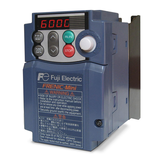
Page 21: External View And Terminal Blocks
Control circuit terminal bock cover Figure 1.2 External Views of FRENIC-Mini (2) View of terminals Barrier for the RS-485 communications port* Control signal cable port DB, P1, P (+) and N (-) wire port L1/R, L2/S, L3/T, U, V, W,... -
Page 22: Storage Environment
1.4 Storage Environment 1.4.1 Temporary storage Store the inverter in an environment that satisfies the requirements listed in Table 1.1. Table 1.1 Environmental Requirements for Storage and Transportation Item Requirements Storage -25 to +70°C Locations where the inverter is not temperature subject to abrupt changes in temperature that would result in the... -
Page 23: Chapter 2 Mounting And Wiring Of The Inverter
Chapter 2 MOUNTING AND WIRING OF THE INVERTER 2.1 Operating Environment Install the inverter in an environment that satisfies the requirements listed in Table 2.1. Table 2.2 Output Current Derating Factor in Table 2.1 Environmental Requirements Relation to Altitude Item Specifications Output current Altitude... -
Page 24: Wiring
(3) Mounting direction Secure the inverter to the mounting base with four screws or bolts (M4) so that the FRENIC-Mini logo faces outwards. Tighten those screws or bolts perpendicular to the mounting base. Do not mount the inverter upside down or horizontally. Doing so will reduce the heat dissipation efficiency of the inverter and cause the overheat protection function to operate, so the inverter will not run. -
Page 25: Terminal Arrangement And Screw Specifications
2.3.2 Terminal arrangement and screw specifications The figures below show the arrangement of the main and control circuit terminals which differs according to inverter type. The two terminals prepared for grounding, which are indicated by the symbol G in Figures A to D, make no distinction between the power supply side (primary circuit) and the motor side (secondary circuit). -
Page 26: Recommended Wire Sizes
(2) Arrangement of the control circuit terminals (common to all FRENIC-Mini models) FWD REV Screw size: M 2 Tightening torque: 0.2 N•m Screw size: M 2.5 Tightening torque: 0.4 N•m Table 2.4 Control Circuit Terminals Dimension of openings in Bared wire... - Page 27 Table 2.6 Recommended Wire Sizes Recommended wire size (mm Main circuit Nomi- Main circuit power input applied Inverter type [L1/R, L2/S, L3/T] Braking Control Inverter motor [L1/L, L2/N] resistor circuit output (kW) Grounding [ [P1, P (+)] [P (+), DB] [U, V, W] w/ DCR w/o DCR...
-
Page 28: Wiring Precautions
2.3.4 Wiring precautions Follow the rules below when performing wiring for the inverter. (1) Make sure that the source voltage is within the rated voltage range specified on the nameplate. (2) Be sure to connect the power wires to the main circuit power input terminals L1/R, L2/S and L3/T (for three-phase voltage input) or L1/L and L2/N (for single-phase voltage input) of the inverter. -
Page 29: Wiring For Main Circuit Terminals And Grounding Terminals
2.3.5 Wiring for main circuit terminals and grounding terminals Follow the procedure below. Figure 2.3 illustrates the wiring procedure with peripheral equipment. Wiring procedure Grounding terminal Inverter output terminals (U, V, and W) and grounding terminal DC reactor connection terminals (P1 and P(+))* Braking resistor connection terminals (P(+) and DB)* DC link bus terminals (P(+) and N(-))* Main circuit power input terminals (L1/R, L2/S and L3/T) or (L1/L and L2/N) - Page 30 The wiring procedure for the FRN0.75C1S-2 is given below as an example. For other inverter types, perform wiring in accordance with their individual terminal arrangement. (Refer to page 2-3.) Grounding terminal ( G) Be sure to ground either of the two grounding terminals for safety and noise reduction. It is stipulated by the Electric Facility Technical Standard that all metal frames of electrical equipment must be grounded to avoid electric shock, fire and other disasters.
- Page 31 No output circuit filter inserted Output circuit filter inserted 5 m or less Power Power Output circuit filter supply supply Motor Motor Inverter Inverter 50 m or less 400 m or less • Do not connect a power factor correcting capacitor or surge absorber to the inverter’s output lines (secondary circuit).
- Page 32 DC reactor terminals, P1 and P (+) Remove the jumper bar from terminals P1 and P(+). Connect a DC reactor (option) to terminals P1 and P(+). • The wiring length should be 10 m or below. • If both a DC reactor and a braking resistor are to be connected to the inverter, secure both wires of the DC reactor and braking resistor together to terminal P(+).
- Page 33 Braking resistor terminals, P(+) and DB Connect terminals P and DB of a braking resistor to terminals P(+) and DB on the main circuit terminal block. (For the braking resistor built-in type, refer to the next page.) When using an external braking resistor, arrange the inverter and braking resistor to keep the wiring length to 5 m or less and twist the two wires or route them together in parallel.
- Page 34 DC link bus terminals, P (+) and N (-) These are provided for the DC link bus powered system. Connect these terminals with terminals P(+) and N (-) of other inverters. Consult your Fuji Electric representative if these terminals are to be used. 2-12...
-
Page 35: Replacing The Main Circuit Terminal Block (Tb) Cover
Main circuit power input terminals, L1/R, L2/S, and L3/T (for three-phase voltage input) or L1/L and L2/N (for single-phase voltage input) 1) For safety, make sure that the molded case circuit breaker (MCCB) or magnetic contactor (MC) is turned off before wiring the main circuit power input terminals. -
Page 36: Wiring For Control Circuit Terminals
2.3.7 Wiring for control circuit terminals In general, sheaths and covers of the control signal cables and wires are not specifically designed to withstand a high electric field (i.e., reinforced insulation is not applied). Therefore, if a control signal cable or wire comes into direct contact with a live conductor of the main circuit, the insulation of the sheath or the cover might break down, which would expose the signal wire to a high voltage of the main circuit. - Page 37 Table 2.8 Symbols, Names and Functions of the Control Circuit Terminals Symbol Name Functions [13] Potenti- Power supply (+10 VDC) for frequency command potentiometer (Potenti- ometer ometer: 1 to 5 kΩ) power Allowable output current: 10 mA supply A potentiometer of 1/2 W rating or more should be connected. [12] Voltage (1) The frequency is commanded according to the external analog input...
- Page 38 Table 2.8 Continued Symbol Name Functions - Since weak analog signals are handled, these signals are especially susceptible to the external noise effects. Route the wiring as short as possible (within 20 m) and use shielded wires. In principle, ground the shielding layer of the shielded wires;...
- Page 39 Table 2.8 Continued Symbol Name Functions [X1] Digital (1) The various signals such as coast-to-stop, alarm from external equip- input 1 ment, and multi-frequency selection can be assigned to terminals [X1] to [X3], [FWD] and [REV] by setting function codes E01 to E03, E98, and [X2] Digital E99.
- Page 40 Table 2.8 Continued Symbol Name Functions Turning on or off [X1], [X2], [X3], [FWD], or [REV] using a relay contact Figure 2.15 shows two examples of a circuit that turns on or off control signal input [X1], [X2], [X3], [FWD], or [REV] using a relay contact. Circuit (a) has a connecting jumper applied to SINK, whereas circuit (b) has one that is applied to SOURCE.
- Page 41 Table 2.8 Continued Symbol Name Functions [FMA] Analog The monitor signal for analog DC voltage (0 to +10 VDC) is output. The monitor signal functions can be selected from the following with function code F31. - Output frequency (before slip compensation) - Output frequency (after slip compensation) - Output current - Output voltage...
- Page 42 Table 2.8 Continued Symbol Name Functions Connecting Programmable Controller (PLC) to Terminal [Y1] Figure 2.18 shows two examples of circuit connection between the transistor output of the inverter’s control circuit and a PLC. In example (a), the input circuit of the PLC serves as the sink for the control circuit, whereas in example (b), it serves as the source for the control circuit.
-
Page 43: Switching Of Sink/Source (Jumper Switch)
2.3.8 Switching of SINK/SOURCE (jumper switch) Before changing the jumper switch, wait for at least five minutes after the power has been turned off, then check that the DC link bus voltage between the terminals P (+) and N (-) does not ex- ceed the safety voltage (+25 VDC) using a multimeter. -
Page 44: Replacing The Control Circuit Terminal Block (Tb) Cover
• Before installing an RS-485 Communications Card, turn off the power, wait more than five minutes, and make sure, using a circuit tester or a similar instrument, that the DC link bus voltage between the terminals P (+) and N (-) has dropped below a safe voltage (+25 VDC). -
Page 45: Cautions Relating To Harmonic Component, Noise, And Leakage Current
2.3.11 Cautions relating to harmonic component, noise, and leakage current (1) Harmonic component Input current to an inverter includes a harmonic component, which may affect other loads and power factor correcting capacitors that are connected to the same power source as the inverter. If the harmonic component causes any problems, connect a DC reactor (option) to the inverter. -
Page 46: Chapter 3 Operation Using The Keypad
Pressing this key displays the details of the problem indicated by the alarm code that has come up on the LED monitor. * FRENIC-Mini features three operation modes: Running, Programming, and Alarm. Refer to Section 3.2 "Overview of Operation Modes."... -
Page 47: Overview Of Operation Modes
Simultaneous keying Simultaneous keying means pressing two keys at the same time (expressed by "+"). FRENIC-Mini supports simultaneous keying as listed below. (For example, the expression " keys" stands for pressing the key while holding down the key.) Table 3.2 Simultaneous Keying... - Page 48 *1 In speed monitor, you can have any of the following displayed according to the setting of function code E48: Output Frequency (Hz), Reference Frequency (Hz), Load Shaft Speed (r/min), Line Speed (m/min), and Constant Rate of Feeding Time (min) *2 Applicable only when PID control is employed.
-
Page 49: Running Mode
3.2.1 Running mode When the inverter is turned on, it automatically enters Running mode. In Running mode, you can: (1) Monitor the running status (e.g., output frequency, output current); (2) Set up the reference frequency and others; (3) Run/stop the motor; and (4) Jog (inch) the motor. - Page 50 Figure 3.3 shows the procedure for selecting the desired monitor item and the sub-item for speed monitoring. *1 The speed monitor displays the output frequency (Hz), reference frequency (Hz), load shaft speed (r/min), line speed (m/min.), or constant rate of feeding time (min.), depending on the setting of function code E48.
- Page 51 Table 3.4 lists the display items for the speed monitor that can be chosen with function code E48. Table 3.4 Display Items on the Speed Monitor Function code Speed monitor items Meaning of Displayed Value Output frequency (before slip Before slip compensation compensation) (Hz) (Factory default) Output frequency (after slip...
- Page 52 Using the keys (1) Set function code F01 to "0: keys on the built-in keypad." This can be done only when the remote keypad is in Running mode. (2) Press the key to specify the reference frequency. The lowest digit will blink. (3) If you need to change the reference frequency, press the key again.
- Page 53 PID process command with those keys. Refer to the FRENIC-Mini User's Manual (MEH446), Chapter 4, Section 4.8 "PID Frequency Command Generator" for details on the PID control. Setting the PID process command with the built-in potentiometer (1) Set function code E60 to "3: PID process command 1."...
-
Page 54: 3 ] Running/Stopping The Motor
Setting up the reference frequency with the keys under PID control To set the reference frequency with the keys under the PID control, you need to specify the following conditions: - Set function code F01 to "0: keys on the built-in keypad." - Select frequency command 1 (Frequency settings from communications link: Disabled, and Multi-frequency settings: Disabled) as manual speed command. -
Page 55: 4 ] Jogging (Inching) The Motor
Operational relationship between function code F02 (Operation method) and Table 3.7 lists the relationship between function code F02 settings and the key, which determines the motor rotational direction. Table 3.7 Rotational Direction of Motor, Specified by F02 If Function code F02 Pressing the is set to: rotates the motor:... -
Page 56: Programming Mode
3.2.2 Programming mode Programming mode provides you with these functions--setting and checking function code data, monitoring maintenance information and checking input/output (I/O) signal status. The functions can be easily selected with the menu-driven system. Table 3.8 lists menus available in Programming mode. - Page 57 Figure 3.4 illustrates the menu transition in Programming mode. * Displayed only when a remote keypad (option) is set up for use. Figure 3.4 Menu Transition in Programming Mode 3-12...
-
Page 58: 1 ] Setting Function Codes - "Data Setting
To set function codes in Menu #1 "Data setting," it is necessary to set function code E52 data to "0" (Function code data editing mode) or "2" (Full-menu mode). The table below lists the function codes available in the FRENIC-Mini. The function codes are displayed on the LED monitor on the keypad as shown below. - Page 59 Table 3.10 List of FRENIC-Mini Function Codes Function code Function code Function Description group F codes F00 to F51 Fundamental func- To be used for basic motor running. tions E codes E01 to E99 Extension terminal To be used to select the functions of the functions control circuit terminals.
- Page 60 Figure 3.5 shows the status transition for Menu #1 "Data setting." Figure 3.5 "Data Setting" Status Transition 3-15...
- Page 61 Basic key operation This section will give a description of the basic key operation, following the example of the function code data changing procedure shown in Figure 3.6. This example shows you how to change function code F01 data from the factory default "Built-in potentiometer (POT) (F01 = 4)"...
-
Page 62: 2 ] Checking Changed Function Codes - "Data Checking
Figure 3.6 Example of Function Code Data Changing Procedure [ 2 ] Checking changed function codes – "Data Checking" Menu #2 "Data checking" in Programming mode allows you to check function codes that have been changed. Only the function code for the data that has been changed from the factory defaults are displayed on the LED monitor. - Page 63 e 52 f 01 * Pressing the key with the data displayed returns to Figure 3.7 "Data Checking" Status Transition (Changes made only to F01, F05, E52) Basic key operation The basic key operation is the same as for "Data setting." To check function codes in Menu #2 "Data checking,"...
-
Page 64: 3 ] Monitoring The Running Status - "Drive Monitoring
[ 3 ] Monitoring the running status – "Drive Monitoring" Menu #3 "Drive monitoring" is used to check the running status during maintenance and test running. The display items for "Drive monitoring" are listed in Table 3.11. Figure 3.8 shows the status transi- tion diagram for "Drive monitoring."... - Page 65 Basic key operation Before checking the running status on the drive monitor, set function code E52 to "2" (full-menu mode). (1) When the inverter is powered on, it automatically enters Running mode. In Running mode, press the key to enter Programming mode. The menu for function selection will be dis- played.
- Page 66 Displaying running status To display the running status in hexadecimal format, each state has been assigned to bits 0 to 15 as listed in Table 3.12. Table 3.13 shows the relationship between each of the status assignments and the LED monitor display. Table 3.14 gives the conversion table from 4-bit binary to hexadecimal. Table 3.12 Running Status Bit Allocation Notation Notation...
- Page 67 Hexadecimal expression A 4-bit binary number can be expressed in hexadecimal format (1 hexadecimal digit). Table 3.14 shows the correspondence between the two notations. The hexadecimals are shown as they appear on the LED monitor. Table 3.14 Binary and Hexadecimal Conversion Binary Hexadecimal Binary...
-
Page 68: 4 ] Checking I/O Signal Status - "I/O Checking
[ 4 ] Checking I/O signal status – "I/O Checking" With Menu #4 "I/O checking," you can display the I/O status of external signals without using a measuring instrument. External signals that can be displayed include digital I/O signals and analog I/O signals. - Page 69 Basic key operation Before checking the status of the I/O signals, set function code E52 to "2: Full-menu mode." (1) When the inverter is powered on, it automatically enters Running mode. In Running mode, press the key to enter Programming mode. The menu for function selection will be dis- played.
- Page 70 "0." Allocated bit data is displayed on the LED monitor in 4 hexadecimal digits ("0" to "F" each). With the FRENIC-Mini, digital input terminals [FWD] and [REV] are assigned to bit 0 and bit 1, respectively. Terminals [X1] through [X3] are assigned to bits 2 through 4. The bit is set to "1" when the corresponding input terminal is short-circuited with terminal [CM] or terminal [PLC] *, and is set to "0"...
- Page 71 Table 3.17 Segment Display for I/O Signal Status in Hexadecimal Format LED No. LED4 LED3 LED2 LED1 Input (RST)* (XR)* (XF)* X1 REV FWD terminal Output 30AC terminal Binary Hexa- decimal on the monitor – : No corresponding control terminal exists. * (XF), (XR), and (RST) are assigned for communication.
-
Page 72: 5 ] Reading Maintenance Information - "Maintenance Information
[ 5 ] Reading maintenance information – "Maintenance Information" Menu #5 "Maintenance information" in Programming mode contains information necessary for performing maintenance on the inverter. Table 3.18 lists the maintenance information display items and Figure 3.10 shows the status transition for maintenance information. * The part in the dotted-line box is applicable only when a remote keypad is set up for operation. - Page 73 Table 3.18 Maintenance Display Items LED Monitor Contents Description shows: Shows the cumulative power-ON time of the inverter. Unit: thousands of hours. When the total ON-time is less than 10000 hours (display: 0.001 to Cumulative run 5_00 9.999), data is shown in units of one hour. When the total time is time 10000 hours or more (display: 10.00 to 65.53), it is shown in units of 10 hours.
-
Page 74: 6 ] Reading Alarm Information - "Alarm Information
[ 6 ] Reading alarm information – "Alarm Information" Menu #6 "Alarm information" in Programming mode shows, in alarm code, the causes of the past 4 alarms. Further, it is also possible to display alarm information that indicates the status of the inverter when the alarm condition occurred. - Page 75 Basic key operation Before viewing alarm information, set function code E52 to "2" (full-menu mode). (1) When the inverter is powered on, it automatically enters Running mode. In Running mode, press the key to enter Programming mode. The menu for function selection will be dis- played.
- Page 76 Table 3.19 Continued LED monitor shows: Contents Description (item No.) Shows the temperature of the heat sink. Max. temperature of 6_11 heat sink Unit: ºC Terminal I/O signal status (displayed with 6_12 the ON/OFF of LED segments) Shows the ON/OFF status of the digital I/O terminals. Refer to Signal input terminal "...
-
Page 77: Alarm Mode
3.2.3 Alarm mode When an abnormal condition occurs, the protective function is invoked to issue an alarm, and the inverter automatically enters Alarm mode. At the same time, an alarm code appears on the LED monitor. Releasing the Alarm and Transferring the Inverter to Running Mode Remove the cause of the alarm and press the key to release the alarm and return to Running mode. - Page 78 Transit to Programming Mode You can also go back to Programming mode by pressing the keys simultaneously while the alarm is displayed, and modify the setting of function codes. Figure 3.12 summarizes the possible transitions between different menu items. Figure 3.12 Alarm Mode Status Transition 3-33...
-
Page 79: Chapter 4 Running The Motor
Chapter 4 RUNNING THE MOTOR 4.1 Running the Motor for a Test 4.1.1 Inspection and preparation prior to the operation Check the following prior to starting the operation. (1) Check if connection is correct. Especially check if the power wires are connected to inverter output terminals U, V and W and that the grounding wire is connected to the ground electrode correctly. -
Page 80: Preparation Before Running The Motor For A Test--Setting Function Code Data
4.1.3 Preparation before running the motor for a test--Setting function code data Before starting running the motor, set function code data specified in Table 4.1 to the motor ratings and your system design values. For the motor, check the rated values printed on the nameplate of the motor. -
Page 81: Test Run
4.1.4 Test run If the user set the function codes wrongly or without completely understanding this Instruction Manual and the FRENIC-Mini User's Manual (MEH446), the motor may rotate with a torque or at a speed not permitted for the machine. -
Page 82: Chapter 5 Function Codes
FUNCTION CODES 5.1 Function Code Tables Function codes enable the FRENIC-Mini series of inverters to be set up to match your system requirements. Each function code consists of a 3-letter string. The first letter is an alphabet that identifies its group and the following two letters are numerals that identify each individual code in the group. - Page 83 Using negative logic for programmable I/O terminals The negative logic signaling system can be used for the digital input and output terminals by setting the function code data specifying the properties for those terminals. Negative logic refers to the inverted ON/OFF (logical value 1 (true)/0 (false)) state of input or output signal. An active-ON signal (the function takes effect if the terminal is short-circuited.) in the normal logic system is functionally equivalent to active-OFF signal (the function takes effect if the terminal is opened.) in the negative logic system.
- Page 84 The following tables list the function codes available for the FRENIC-Mini series of inverters. If you find any [-] (not available here) mark in the related page column of the function code tables, refer to FRENIC-Mini User’s manual (MEH446) for details.
- Page 85 *1 Values in parentheses ( ) in the above table denote default settings for the EU version except the three-phase 200 V class series of inverters.
- Page 86 *4 Default settings for inverters with ROM version C1S11299 or earlier: F43 = 0 and F44 = 200 (For the ROM version checking procedure, refer to Chapter 3, Section 3.2.2 [5] "Reading maintenance information.") *5 The default setting of function code F50 is 999 for standard models, and 0 for braking resistor built-in type. E codes: Extension Terminal Functions...
- Page 87 Fuji standard motor" differ depending upon the rated input voltage and rated capacity. Refer to Table 5.1 "Fuji Standard Motor Parameters" on page 5-12. (Note) Function codes E45 to E47 appear on the LED monitor; however, the FRENIC-Mini series of inverters does not recognize these codes.
- Page 89 C codes: Control Functions of Frequency...
- Page 90 P codes: Motor Parameters H codes: High Performance Functions *2 "Fuji's standard torque boost," "Nominal rated current of Fuji standard motor," and "Nominal rated capacity of Fuji standard motor" differ depending upon the rated input voltage and rated capacity. Refer to Table 5.1 "Fuji Standard Motor Parameters"...
- Page 91 *6 The value in parentheses ( ) for H95 denotes the default setting for the EU version. If initialized by H03, the H95 data reverts to "1" in the EU version. (Note 1) Function code H71 appears on the LED monitor; however, the FRENIC-Mini series of inverters does not recognize this code.
- Page 92 J codes: Application Functions y codes: Link Functions 5-11...
- Page 93 * The table below lists the factory settings of "Fuji's standard torque boost," "Nominal rated current of Fuji standard motor," and "Nominal rated capacity of Fuji standard motor" in the "Default setting" column of the above tables. Table 5.1 Fuji Standard Motor Parameters Nominal rated Fuji's standard Nominal rated current of...
-
Page 94: Overview Of Function Codes
5.2 Overview of Function Codes This section provides an overview of the function codes frequently used for the FRENIC-Mini series of inverter. For details about the function codes given below and other function codes not given below, refer to the FRENIC-Mini User’s Manual (MEH446), Chapter 9 "FUNCTION CODES" and the RS-485 Communication User's Manual (MEH448). - Page 95 Operation Method Selects a source issuing a run command--keypad or external control signal input. - If F02 = 0, 2, or 3, the inverter can run the motor by the keys on the built-in keypad. The motor rotational direction can be specified in two ways, ei- ther by control signal input (F02 = 0) or by use of prefixed forward or reverse rotation (F02 = 2 or 3).
- Page 96 • If you have assigned the FWD or REV function to the [FWD] or [REV] terminal, you cannot change the setting of function code F02 while the terminals [FWD] and [CM]* or the terminals [REV] and [CM]* are short-circuited. • If you have specified the external signal (F02 = 1) as the running command and have assigned functions other than the FWD or REV function to the [FWD] or [REV] terminal, caution should be exercised in changing the settings.
- Page 97 If F05 is set to match the rated voltage of the motor, motor efficiency will be better than that it is set to 0. Therefore, when brakes are applied to the motor, energy loss decreases and the motor regenerates larger braking energy, which can easily cause the overvoltage protection function ( where n = ) to be activated.
- Page 98 V/f pattern with single non-linear point inside the base frequency You can also set the optional non-linear V/f range (H50: Frequency) for frequencies exceeding the base frequency (F40). Acceleration Time 1, Deceleration Time 1 The acceleration time specifies the length of time the frequency increases from 0 Hz to the maximum frequency.
- Page 99 In case the reference frequency is lower than the maximum frequency (F03) The actual acceleration and deceleration times are shorter than the specified ac- celeration time and deceleration time. • If you choose S-curved acceleration/deceleration or curvilinear accel- eration/deceleration in "curvilinear acceleration/deceleration" (H07), the actual acceleration/deceleration times are longer than the specified times.
- Page 100 Manual torque boost In manual torque boost mode, the inverter maintains the output at a constant level regardless of the load. When you use this mode, select the appropriate V/f pattern (variable torque or constant torque characteristics) with Load Selection (F37). To keep the motor starting torque, manually select optimal inverter output voltage for the motor and load by setting an optimal torque boost rate to F09 in accordance with the motor and its load.
- Page 101 Use auto-energy saving only where the base frequency is 60 Hz or lower. If the base frequency is higher than 60 Hz, then you may get little or no energy saving effect. The auto energy saving operation is designed for use with the frequency lower than the base frequency.
- Page 102 5 minutes by factory default. Data entry range: 0.5 to 75.0 (minutes, in 0.1-minute increment) Refer to the FRENIC-Mini User’s Manual (MEH446), Chapter 9 "FUNCTION CODES" for details of the shaft-driven cooling fan and characteristics of the electronic thermal function.
- Page 103 - Trip immediately (F14 = 0) If a momentary power failure occurs when the inverter is in Running mode so that the inverter detects undervoltage of the DC link bus, then the inverter immediately stops its output and displays the undervoltage alarm on the LED monitor.
- Page 104 This setting is optimal for operations in which the motor speed quickly slows down to 0 r/min due to the heavy load with a very small moment of inertia if the motor coasts to a stop because of the momentary power failure. •...
- Page 105 • When you change the upper frequency limit (F15) in order to increase the running frequency, be sure to change the maximum frequency (F03) accordingly. • Maintain the following relationship among the parameters for frequency control: F03 F15 > F16 F23 F25, or F03 F15 > F16 F25 F23, where, F23 is the starting frequency and F25 is the stopping frequency.
- Page 106 The relations stated above are indicated in the following expressions. (1) If analog input bias base point: Frequency Setting Bias (F18) (2) If analog input > bias base point: Frequency Setting − (Gain) (Bias) × Analog input − (Gain base point) (Bias base...
- Page 107 H95 specifies the DC braking response mode as follows: If H95 is Braking mode Meaning set to: The DC braking current gradually ramps up. (The torque Slow response may not be sufficient at the start of DC braking.) The DC braking current quickly ramps up. (Depending on Quick response the inertia of the moving loads or the coupling state, the revolution may be unstable.)
- Page 108 F23, F25 Starting Frequency and Stop Frequency At the startup of an inverter, the initial output frequency is equal to the starting frequency. The inverter stops its output at the stop frequency. Set the starting frequency to a level that will enable the motor to generate enough torque for startup.
- Page 109 Analog Output [FMA] (Voltage adjustment and Function) F31 allows you to output monitored data (such as the output frequency or output current) to terminal [FMA] as an analog DC voltage that can be adjusted with F30 for the meter scale. Voltage adjustment (F30) Adjust the output voltage level within the range of 0 to 200%, supposing the monitored amount of the monitor selected with function code F31 as 100%.
- Page 110 For three-phase 200 V and single-phase 200 V/100 V class series of inverters Outputting the output current in an analog format (FMA) (F31 = 2) The analog output terminal [FMA] outputs 10 V, that is, 200% of the ref- erence current I (A), supposing the output gain selected with F30 as 100%.
- Page 111 For built-in braking resistors, you may set 0 and 0.000 to F50 and F51, respectively. Doing so will automatically apply the settings given in the table on the next page. Refer to the FRENIC-Mini User’s Manual (MEH446), Chapter 7, Section 7.2 "Selecting a Baking Resistor" for details.
- Page 112 The following tables list the discharging capability and allowable average loss of the FRENIC-Mini series inverters. These values are determined by inverter model and specifications (built-in or external type) of braking resistors. Built-in braking resistor Continuous braking Repetitive braking Power...
- Page 113 External braking resistor Standard Models The braking resistor is protected from overheating by a thermal relay incorporated in the braking resistor. Assign "Enable external alarm trip" THR to one of the inverter’s digital input terminals [X1], [X2], [X3], [FWD], and [REV], and connect it to the terminals 2 and 1 of the braking resistor. If you choose not to use the thermal relay incorporated in the braking resistor, set up the overheat protection device using the values given in the table below.
- Page 114 10% ED Models Continuous braking Repetitive braking (Braking torque: (Period: 100 sec. or Resis- Power Braking 100%) less) tance pac- supply Inverter type resistor Q'ty Discharg- Allowable (Ω) Braking Duty voltage type average time cycle capability loss (%ED) (kWs) (kW) FRN0.4C1 -2 DB0.75-2C 0.075...
- Page 115 E01 to E03, Terminal [X1] to [X3] Function E98, E99 Terminal [FWD] and [REV] Function Function codes E01 to E03, E98 and E99 allow you to assign commands to ter- minals [X1] to [X3], [FWD], and [REV] which are general-purpose, programmable, digital input terminals.
- Page 116 Enable 3-wire operation--HLD) (Function code data = 6) Digital input signal HLD may self-hold the forward FWD/ reverse REV run com- mands given at the external signal input terminals to enable 3-wire inverter opera- tion. Shorting the circuit between the HLD-assigned terminal and terminal [CM] (i.e., when HLD is ON) will self-hold the FWD or REV command.
- Page 117 If the PID control is disabled with the Hz/PID being off, the inverter runs the motor with the frequency manually set by any of multistep, keypad, or analog input. Refer to the FRENIC-Mini User's Manual (MEH446), Chapter 4, Section 4.8 "PID Frequency Command Generator" for details.
- Page 118 Switch normal/inverse operation--IVS (Function code data = 21) Turning the IVS command on/off switches the output frequency control between normal (proportional to the reference frequency components) and inverse operation for the PID process or manually reference frequencies. To select the inverse op- eration, turn the IVS command on.
- Page 119 Terminal [Y1] Function E20, E27 Terminal [30A/B/C] Function E20 and E27 may assign output signals to terminals [Y1] (transistor switch) and [30A], [30B] and [30C] (mechanical relay contacts) which are general-purpose programmable output terminals. These function codes may also switch the logic system between normal and negative to define how the inverter logic interprets either ON or OFF status of each terminal.
- Page 120 Undervoltage detected--LU (Function code data = 3) This signal is turned on when the DC link bus voltage of the inverter drops below the specified level or when the motor stops due to activation of the undervoltage pro- tection feature (undervoltage trip). It is turned off if the DC link bus voltage exceeds the specified level.
- Page 121 This function provides a tentative information for service life of the parts. If this signal is issued, check the service life of these parts in your system according to the maintenance procedure to determine whether the parts should be replaced or not. To maintain stable and reliable operation and avoid unexpected failures, daily and periodic maintenance must be performed.
- Page 122 Coefficient for Constant Feeding Rate Time Coefficient for Speed Indication This function code sets a coefficient to be used for setting the constant rate of feeding time, load shaft speed or line speed and for displaying its output status. Coeff. Speed Indication (E50)
- Page 123 Timer Operation Enables or disables timer operation. If it is enabled, entering a run command will run the inverter to drive the motor for the period preset to the timer. An example of timer operation • Setting up the timer conditions beforehand - Set C21 to 1 to enable timer operation.
- Page 124 P02, P03 Motor Parameters (Rated capacity and Rated current) Sets the nominal rated capacity that is denoted on the rating nameplate of the motor. For FRN4.0C1 -4 **, the default setting for P02 is 3.7. Motor Parameters (Slip compensation gain) Sets the gain to compensate for the motor slip frequency.
- Page 125 Data Initialization Initializes the current function code settings to the factory defaults or initializes the motor constants (parameters). To change the H03 data, it is necessary to press the keys or the keys simultaneously. If H03 is set to: Function Disable initialization (Settings made by the user manually will be retained.) Initialize all function code data to the factory defaults...
- Page 126 If P99 (Motor selection) is set to 0 (Fuji standard 8-series motors), 3 (Fuji standard 6-series motors), or 4 (Other motors): Rated current (A) Setting range If P99 (Motor selection) is set to: Nomi- (kW) Power applied supply motor voltage Shipping destination Shipping destination Shipping destination...
- Page 127 If P99 (Motor selection) is set to 1 (HP motors): Rated current (A) Setting Nomi- range If P99 (Motor selection) is set to: Power (HP) applied supply motor voltage Function Shipping destination (Version) (HP) code Asia Japan 0.01 to 0.10 0.44 0.44 0.44...
- Page 128 H04, H05 Auto-reset (Times and Reset interval) To automatically exit from the alarm status and restart the inverter, use the retry functions. The inverter automatically exits from Alarm mode and restarts without issuing a block alarm even if it has entered the forced Alarm mode. If the inverter has entered Alarm mode many times in excess of the number of times specified by function code H04, it issues a block alarm and does not exit Alarm mode for re- starting.
- Page 129 Alarm mode and trip. When setting the acceleration time, therefore, you need to take into account the load condition and moment of inertia. Refer to the FRENIC-Mini User's Manual (MEH446), Chapter 7, Section 7.1, "Selecting Motors and Inverters." 5-48...
- Page 130 Automatic Deceleration The moment a regenerative energy exceeding the braking capacity of inverter is returned during deceleration, the inverter will stop its output and enter overvoltage Alarm mode. If regenerative energy suppressing control is enabled, the inverter lengthens the deceleration time to 3 times the preset time and decreases the de- celeration torque to 1/3 when the DC link bus voltage exceeds the preset voltage suppressing level.
- Page 131 Start check function The inverter prohibits any run commands to be executed and displays on the LED of keypad when: - The power is first applied. - The key is pressed or the RST signal is turned on to cancel the alarm. - Link command LE has switched inverter operations.
-
Page 132: Chapter 6 Troubleshooting
(1) First, check that the inverter is correctly wired, referring to Chapter 2, Section 2.3.5 "Wiring for Main Circuit Terminals and Grounding Terminals." (2) Check whether an alarm code is displayed on the LED monitor. If any problems persist after the above recovery procedure, contact your Fuji Electric representative. - Page 133 Quick reference table of alarm codes Alarm code Name Refer to Alarm code Name Refer to PTC thermistor for motor p.6-13 protection Overheat protection for Overcurrent protection p.6-9 p.6-14 braking resistor Electronic thermal overload p.6-14 relay Overload protection p.6-15 Memory error p.6-15 Overvoltage protection p.6-10...
-
Page 134: If No Alarm Code Appears On The Led Monitor
#2 "Data checking" and Menu #4 "I/O checking" using the keypad. and the run command was stopped. *Refer to the FRENIC-Mini User’s Manual (MEH446), Chapter 4. Correct any incorrect function code data settings (e.g., cancel the higher priority run command). (6) The reference frequency... - Page 135 *Refer the FRENIC-Mini User’s Manual (MEH446), Chapter 4. Correct any incorrect function code data settings (e.g. cancel the higher priority run command). (8) The peak and bottom Check the data of function codes F15 (frequency limiter (high)) and F16 (frequency limiter (low)).
- Page 136 *Refer to the FRENIC-Mini User’s Manual (MEH446), Chapter 4. was active and the Correct any incorrect function code data settings (e.g. reference frequency was cancel higher priority run commands, etc.).
- Page 137 [ 4 ] If the speed variation and current vibration (such as hunting) occur at the constant speed Possible Causes What to Check and Suggested Measures (1) The frequency command Check the signals for the frequency command with Menu #4 "I/O checking"...
- Page 138 Possible Causes What to Check and Suggested Measures (3) The automatic Check the data of function code H69 (Automatic deceleration deceleration was active. (mode selection)). Consider the use of a braking resistor. Increase the deceleration time (F08 and E11). (4) Overload Measure the output current.
-
Page 139: Problems With Inverter Settings
6.2.2 Problems with inverter settings [ 1 ] Data of function codes cannot be changed Possible Causes What to Check and Suggested Measures (1) An attempt was made to Check if the inverter is running with Menu #3 "Drive monitoring" change function code data using the keypad and then confirm whether the data of the that cannot be changed... -
Page 140: If An Alarm Code Appears On The Led Monitor
Check if noise control measures are appropriate (e.g., correct noise grounding and routing of control and main circuit wires). Implement noise control measures. For details, refer to "Appendix A" of the FRENIC-Mini User’s Manual (MEH446). Enable the retry function (H04). - Page 141 Check if the DC link bus voltage was below the protective level noise. when the alarm occurred. Improve noise control. For details, refer to "Appendix A" of the FRENIC-Mini User’s Manual (MEH446). Enable the retry function (H04). [ 3 ] Undervoltage protection Problem DC link bus voltage was below the undervoltage detection level.
- Page 142 Possible Causes What to Check and Suggested Measures (2) The power to the inverter Check with LED monitor if the power to the inverter was was switched back on too switched back on although its control circuit was still operating. soon (with F14 = 1) Make the interval longer for re-power on.
- Page 143 Tighten the terminal screws to the recommended torque. (4) A single-phase motor has Single-phase motors cannot be used. Note that the been connected FRENIC-Mini only drives three-phase induction motors. [ 6 ] Overheat protection for heat sink Problem Temperature around heat sink rose.
- Page 144 [ 7 ] External alarm input Problem External alarm was inputted (THR). Possible Causes What to Check and Suggested Measures (1) An alarm function of the Inspect external equipment operation. external equipment was Remove the cause of the alarm that occurred. activated.
- Page 145 [ 9 ] Overheat protection for braking resistor Problem Thermal protection for braking resistor activated. Possible Causes What to Check and Suggested Measures (1) Braking load was too Recalculate the relation between the braking load and braking capacity. heavy. Lighten the braking load. Reconsider the choice of the braking resistor in order to improve braking ability.
- Page 146 [ 11 ] Overload protection Problem Temperature inside inverter rose abnormally. Possible Causes What to Check and Suggested Measures (1) Temperature around the Measure the temperature around the inverter. inverter exceeded that of Lower the temperature (e.g., ventilate the panel well). inverter specifications.
- Page 147 (e.g., correct grounding and routing of control and main circuit wires). Improve noise control. For details, refer to "Appendix A" of the FRENIC-Mini User’s Manual (MEH446). (3) The remote keypad Check that alarm does not occur if you connect another malfunctioned.
- Page 148 [ 15 ] Operation protection Problem An error occurred due to incorrect operation of the motor. Possible Causes What to Check and Suggested Measures Even though a run command was present at the input terminal (1) The key was pressed or the communication port, the inverter was forced to when H96 = 1 or 3.
- Page 149 (3) The control circuit failed. Check if occurs each time power is switched off. This problem was caused by a problem of the printed circuit board (PCB) (on which the CPU is mounted). Contact your Fuji Electric representative. 6-18...
-
Page 150: If An Abnormal Pattern Appears On The Led Monitor While No Alarm Code Is Displayed
6.4 If an Abnormal Pattern Appears on the LED Monitor while No Alarm Code is Displayed [ 1 ] – – – – (center bar) appears Problem A center bar (– – – –) has appeared on the LED monitor. Possible Causes What to Check and Suggested Measures (1) When PID control had... - Page 151 [ 2 ] _ _ _ _ (under bar) appears Problem An under bar ( _ _ _ _ ) appeared on the LED monitor when you pressed the or entered a normal start/stop command FWD or a reverse start/stop command REV.
-
Page 152: Chapter 7 Maintenance And Inspection
Chapter 7 MAINTENANCE AND INSPECTION Perform daily and periodic inspection to avoid trouble and keep reliable operation for a long time. Take care of the following items during work. • Before starting inspection and maintenance, first turn off the inverter and wait at least 5 minutes. - Page 153 Table 7.1 List of Periodic Inspections Check part Check item How to inspect Evaluation criteria 1) Check the ambient 1) Check visually or 1) The standard Environment temperature, humidity, measure using specification must vibration and atmosphere apparatus. be satisfied. (dust, gas, oil mist, or water drops).
- Page 154 Table 7.1 Continued Check part Check item How to inspect Evaluation criteria Filtering 1) Check for electrolyte leakage, 1),2) 1),2) capacitor discoloration, cracks and Visual inspection No abnormalities swelling of the case. (Note) 2) Check if the safety valve does not protrude remarkably.
- Page 155 Judgement of service life using maintenance information Menu #5 "Maintenance information" in Programming mode can be used to display data for the judgement of replacement of "DC link bus capacitor," "electrolytic capacitor on the printed circuit board," and "cooling fan" as a guide. If the replacement data is out of the judgement level for early warning, an early warning signal is output to an external device through terminal [Y1] (function code E20).
- Page 156 (2) Electrolytic capacitor on the printed circuit board The inverter keeps an accumulative total of the number of hours that power has been applied to the control circuit and displays it on the LED monitor. Use this to determine when the capacitor should be replaced.
-
Page 157: Measurement Of Electrical Amounts In Main Circuit
7.3 Measurement of Electrical Amounts in Main Circuit Because the voltage and current of the power supply (input, primary circuit) of the main circuit of the inverter and those of the motor (output, secondary circuit) include harmonic components, the readings may vary with the type of the meter. Use meters indicated in Table 7.3 when measuring with meters for commercial frequencies. -
Page 158: Insulation Test
A dielectric strength test will cause breakage of the inverter similarly to the Megger test if the test procedure is wrong. When the dielectric strength test is necessary, contact your Fuji Electric representative. -
Page 159: List Of Periodical Replacement Parts
2) However, in cases where the use environment, conditions of use, use frequency and times used, etc., have an effect on product life, this warranty period may not apply. 3) Furthermore, the warranty period for parts restored by Fuji Electric's Service Department is ''6 months from the date that repairs are completed.''... - Page 160 1) In the event that breakdown occurs during the product's warranty period which is the responsibility of Fuji Electric, Fuji Electric will replace or repair the part of the product that has broken down free of charge at the place where the product was purchased or where it was delivered.
- Page 161 [ 3 ] Repair period after production stop, spare parts supply period (holding period) Concerning models (products) which have gone out of production, this company will perform repairs for a period of 7 years after production stop, counting from the month and year when the production stop occurs.
-
Page 162: Chapter 8 Specifications
*10 Average braking torque obtained by use of an external braking resistor (standard type available as option). *11 To make FRENIC-Mini compliant with category TYPE1 of the UL Standard (or NEMA1), an optional NEMA1 kit is required. Note that the TYPE1-compliant FRENIC-Mini should be used in the ambient temperature range from -10 to +40°C. -
Page 163: Three-Phase 400 V Class Series
*9 Average braking torque obtained by use of an external braking resistor (standard type available as option). *10 To make FRENIC-Mini compliant with category TYPE1 of the UL Standard (or NEMA1), an optional NEMA1 kit is required. Note that the TYPE1-compliant FRENIC-Mini should be used in the ambient temperature range from -10 to +40°C. -
Page 164: Single-Phase 200 V Class Series
Average braking torque obtained by use of an external braking resistor (standard type available as option). *10 To make FRENIC-Mini compliant with category TYPE1 of the UL Standard (or NEMA1), an optional NEMA1 kit is required. Note that the TYPE1-compliant FRENIC-Mini should be used in the ambient temperature range from -10 to +40°C. -
Page 165: Single-Phase 100 V Class Series
*8 Average braking torque obtained by use of an external braking resistor (standard type available as option). *9 To make FRENIC-Mini compliant with category TYPE1 of the UL Standard (or NEMA1), an optional NEMA1 kit is required. Note that the TYPE1-compliant FRENIC-Mini should be used in the ambient temperature range from -10 to +40°C. -
Page 166: Models Available On Order
8.2 Models Available on Order In the EU version, the EMC filter built-in type is provided as a standard model. In other versions, it is available on order. 8.2.1 EMC filter built-in type Three-Phase 200 and 400 V class series *1 Fuji 4-pole standard motors ∗... -
Page 167: Common Specifications
8.3 Common Specifications... -
Page 169: Terminal Specifications
8.4 Terminal Specifications 8.4.1 Terminal functions For details about the main and control circuit terminals, refer to Chapter 2, Section 2.3.5 and Section 2.3.7 (Table 2.8), respectively. 8.4.2 Connection diagram in operation by external signal inputs (Note 1) Install a recommended molded case circuit breaker (MCCB) or a residual-current-operated protective device (RCD)/earth leakage circuit breaker (ELCB) (with overcurrent protection) in the input (primary) circuit of the inverter to protect wiring. - Page 170 (Note 5) Frequency can be set by connecting a frequency setting device (external potentiometer) between the terminals [11], [12], and [13] instead of inputting voltage signal (0 to +10 VDC or 0 to +5 VDC) between the terminals [12] and [11]. (Note 6) For the wiring of the control circuit, use shielded or twisted wires.
-
Page 171: External Dimensions
8.5 External Dimensions 8.5.1 Standard models and models available on order (braking resistor built-in type) Note 1) A box ( ) in the above table replaces A, C, E, or J depending on the shipping destination. 2) Asterisks (∗∗) in the above table replace numbers which denote the following: 21: Braking resistor built-in type, None: Standard. - Page 172 Note 1) A box ( ) in the above table replaces A, C, E, or J depending on the shipping destination. 2) Asterisks (∗∗) in the above table replace numbers which denote the following: 21: Braking resistor built-in type, None: Standard. 8-11...
-
Page 173: Models Available On Order (Emc Filter Built-In Type)
8.5.2 Models available on order (EMC filter built-in type) Note: # in the above table denotes the shipping destination as shown below. Shipping destination (Version)/ Shipping destination code Language in Instruction manual Asia/English China/Chinese EU/ English Japan/Japanese 8-12... - Page 174 8-13...
-
Page 175: Protective Functions
8.6 Protective Functions "—": Not applicable. Alarm Name Description monitor output displays [30A,B,C] Overcurrent - Stops the inverter output to protect the During protection inverter from an overcurrent resulting from acceleration overload. During - Stops the inverter output to protect the deceleration inverter from an overcurrent due to a short During running... - Page 176 Alarm Name Description monitor output displays [30A,B,C] Electronic In the following cases, the inverter stops running the motor to thermal protect the motor in accordance with the electronic thermal overload function setting. relay - Protects general-purpose motors over the entire frequency range.
- Page 177 Alarm Name Description monitor output displays [30A,B,C] Operation Start Inverters prohibit any run operations and displays Protection check on the LED of keypad if any run command is function present when: - Powering up - An alarm ( key turned on) is released or an alarm reset RST is input.
-
Page 178: Chapter 9 List Of Peripheral Equipment And Options
The table below lists the main peripheral equipment and options that are connected to the FRENIC-Mini. Use them in accordance with your system requirements. For details, refer to the FRENIC-Mini User's Manual (MEH446), Chapter 6 "SELECTING PERIPHERAL EQUIPMENT." Name of... - Page 179 Name of peripheral Function and application equipment Molded case circuit breaker Earth leakage When connecting the inverter to the power supply, add a recommended circuit breaker * molded case circuit breaker and earth leakage circuit breaker* in the path * with overcurrent of power supply.
- Page 180 Name of option Function and application Braking resistors A braking resistor converts regenerative energy generated from deceleration (Standard model) of the motor and converts it to heat for consumption. Use of a braking (DBRs) resistor results in improved deceleration performance of the inverter. DC reactors A DCR is mainly used for power supply normalization and for supplied (DCRs)
- Page 181 Name of option Function and application Ferrite ring reactors for An ACL is used to reduce radio noise emitted by the inverter. reducing radio An ACL suppresses the outflow of high frequency harmonics caused by frequency noise switching operation for the power supply (primary) lines inside the (ACL) inverter.
- Page 182 Name of option Function and application FRENIC-Mini series of inverters can be installed to the control board of Mounting adapters your system using mounting adapters which utilize the mounting holes used for conventional inverters (FVR-E11S series of 0.75 kW or below or 3.7 kW).
-
Page 183: Chapter 10 Application Of Dc Reactors (Dcrs)
Individual inverter manufacturers have voluntarily employed harmonics suppression measures. It is recommended that DC reactors (DCRs) specified in Table 10.1 be connected to the FRENIC-Mini series of inverters. Table 10.1 List of DC Reactors (DCRs) -
Page 184: Chapter 11 Compliance With Standards
11.1.2 Considerations when using FRENIC-Mini in systems to be certified by UL and cUL If you want to use the FRENIC-Mini series of inverters as a part of UL Standards or CSA Standards (cUL certified) certified product, refer to the related guidelines described on page ix. -
Page 185: Compliance With Emc Standards
11.3 Compliance with EMC Standards 11.3.1 General The CE marking on inverters does not ensure that the entire equipment including our CE-marked products is compliant with the EMC Directive. Therefore, CE marking for the equipment shall be the responsibility of the equipment manufacturer. For this reason, Fuji’s CE mark is indicated under the condition that the product shall be used within equipment meeting all requirements for the relevant Directives. - Page 186 (3) Use shielded wires for the control signals of the inverter to input to/output from the control terminals. Firmly clamp the control wire shields to the EMC grounding flange (in the same way as the motor cables). Figure 11.2 Connecting Shielded Cables <When an RS-485 Communications Card (optional) is used>...
- Page 187 (4) If noise from the inverter exceeds the permissible level, enclose the inverter and its peripherals within a metal panel as shown in Figure 11.5. Figure 11.5 Installing the Inverter into a Metal Panel ■ In case an outboard, EMC-compliant (optional) is used 1) Install the inverter and the filter on a grounded metal plate.
-
Page 188: Leakage Current Of Emc-Filter Built-In Type Inverter And Outboard Emc-Complaint Filter
11.3.3 Leakage current of EMC-filter built-in type inverter and outboard EMC-complaint filter Table 11.1 Leakage current of EMC filter built-in type inverter *2), *3) Leakage current (mA) Input Inverter type Power Normal Worst FRN0.1C1E-2 FRN0.2C1E-2 FRN0.4C1E-2 Three- FRN0.75C1E-2 phase 200V FRN1.5C1E-2 13.0 20.0... - Page 189 Table 11.2 Leakage current of EMC-compliant filter (optional) *2), *3) Leakage current (mA) Input power Inverter type Filter type Normal Worst FRN0.1C1S-2 FRN0.2C1S-2 FS5956-6-46 (EFL-0.75E11-2) FRN0.4C1S-2 Three-phase FRN0.75C1S-2 200V FRN1.5C1S-2 FS5956-26-47 FRN2.2C1S-2 (EFL-4.0E11-2) FRN3.7C1S-2 FRN0.4C1S-4 FRN0.75C1S-4 15TDHS84 FRN1.5C1S-4 Three-phase 27.0 400V (Delta Electronics, Inc.) FRN2.2C1S-4...
-
Page 190: Harmonic Component Regulation In The Eu
11.4 Harmonic Component Regulation in the EU 11.4.1 General comments When you use general-purpose industrial inverters in the EU, the harmonics emitted from the inverter to power lines are strictly regulated as stated below. If an inverter whose rated input is 1 kW or less is connected to public low-voltage power supply, it is regulated by the harmonics emission regulations from inverters to power lines (with the exception of industrial low-voltage power lines). -
Page 191: Compliance With The Harmonic Component Regulation
11.5.2 Points for consideration when using the FRENIC-Mini series in a system to be certified by the Low Voltage Directive in the EU If you want to use the FRENIC-Mini series of inverters in systems/equipment in the EU, refer to the guidelines on page vii. - Page 192 MEMO...
- Page 193 MEMO...
- Page 194 MEMO...
- Page 195 In no event will Fuji Electric FA Components & Systems Co., Ltd. be liable for any direct or indirect damages resulting from the application of the information in this manual.
- Page 196 Fuji Electric FA Components & Systems Co., Ltd. Mitsui Sumitomo Bank Ningyo-cho Bldg., 5-7, Nihonbashi, Odemma-cho, Chuo-ku, Tokyo, 103-0011, Japan Phone: +81 3 5847 8011 Fax: +81 3 5847 8172 http://www.fujielectric.co.jp/fcs/ 2007-02 (B07/J02) XXCM...
Need help?
Do you have a question about the Frenic-Mini and is the answer not in the manual?
Questions and answers