Table of Contents
Advertisement
High Performance, Multifunction Inverter
This product is designed to drive a three-phase induction motor. Read through this manual to become familiar with proper
handling and correct use.
Improper handling might result in incorrect operation, short life cycle, or failure of this product as well as the motor.
Deliver this manual to the end user of this product. Keep this manual in a safe place until this product is discarded.
For instructions on how to use an optional device, refer to the instruction and installation manuals for that optional device.
Fuji Electric Co., Ltd.
Fuji Electric Corp. of America
Instruction Manual
INR-SI47-1457a-E
Advertisement
Table of Contents
Troubleshooting

Subscribe to Our Youtube Channel
Related Manuals for Fuji Electric FRENIC MEGA


Summary of Contents for Fuji Electric FRENIC MEGA
- Page 1 Deliver this manual to the end user of this product. Keep this manual in a safe place until this product is discarded. For instructions on how to use an optional device, refer to the instruction and installation manuals for that optional device. Fuji Electric Co., Ltd. Fuji Electric Corp. of America INR-SI47-1457a-E...
- Page 2 Copyright © 2010-2011 Fuji Electric Corp. of America All rights reserved. No part of this publication may be reproduced or copied without prior written permission from Fuji Electric Corp. of America. All products and company names mentioned in this manual are trademarks or registered trademarks of their respective holders.
-
Page 3: Safety Precautions
Preface This product is designed to drive a three-phase induction motor. Read through this manual to become familiar with proper handling and correct use. Improper handling might result in incorrect operation, shorter life cycle, or failure of this product as well as the motor. Have this manual delivered to the end user of this product. - Page 4 • Do not support the inverter by its front cover during transportation. Doing so could cause a drop of the inverter and injuries. • Prevent lint, paper fibers, sawdust, dust, metallic chips, or other foreign materials from getting into the inverter or from accumulating on the heat sink.
- Page 5 • Before changing the switches or touching the control circuit terminal symbol plate, turn OFF the power and wait at least five minutes for inverters of 40 HP or below, or at least ten minutes for inverters of 50 HP or above. Make sure that the LED monitor and charging lamp are turned OFF.
- Page 6 • Do not touch the heat sink and braking resistor because they become very hot. Doing so could cause burns. • The DC brake function of the inverter does not provide any holding mechanism. Injuries could occur. • Ensure safety before modifying the function code settings. Run commands (e.g., "Run forward"...
-
Page 7: Conformity To The Low Voltage Directive In The Eu
Conformity to the Low Voltage Directive in the EU If installed according to the guidelines given below, inverters marked with CE are considered as compliant with the Low Voltage Directive 2006/95/EC. Compliance with European Standards Adjustable speed electrical power drive systems (PDS). Part 5-1: Safety requirements. - Page 8 Conformity to the Low Voltage Directive in the EU (Continued) 3. When used with the inverter, a molded case circuit breaker (MCCB), residual-current-operated protective device (RCD)/earth leakage circuit breaker (ELCB) or magnetic contactor (MC) should conform to the EN or IEC standards. 4.
- Page 9 Conformity to the Low Voltage Directive in the EU (Continued) Recommended wire size (mm Main circuit Main power MCCB or Nominal applied input *2 RCD/ELCB *1 motor [L1/R, L2/S, L3/T] (HP) Rated current Inverter type Inverter’s grounding *3 [ G] Three- Single- phase...
- Page 10 Conformity to the Low Voltage Directive in the EU (Continued) Recommended wire size (mm Main circuit Main power MCCB or Nominal applied input *2 RCD/ELCB *1 motor [L1/R, L2/S, L3/T] (HP) Rated current Inverter type Inverter’s grounding *3 [ G] Three- Single- phase...
-
Page 11: Conformity With Ul Standards And Csa Standards (Cul-Listed For Canada)
Conformity with UL standards and CSA standards (cUL-listed for Canada) UL/cUL-listed inverters are subject to the regulations set forth by the UL standards and CSA standards (cUL-listed for Canada) by installation within precautions listed below. 1. Solid state motor overload protection (motor protection by electronic thermal overload relay) is provided in each model. Use function codes F10 to F12 to set the protection level. - Page 12 Conformity with UL standards and CSA standards (cUL-listed for Canada) (continued) 8. Install UL certified fuses or circuit breaker between the power supply and the inverter, referring to the table below. Required Wire size torque AWG (mm Nominal applied lb-in (N m) motor Main terminal (HP)
- Page 13 Conformity with UL standards and CSA standards (cUL-listed for Canada) (continued) Required Wire size torque AWG (mm Nominal applied lb-in (N m) motor Main terminal (HP) L1/R, L2/S, L3/T U, V, W Inverter type Three- Single- phase phase 0.25 FRNF50G1S-4U 10.6 (1.2) FRN001G1S-4U...
- Page 14 Conformity with UL standards and CSA standards (cUL-listed for Canada) (continued) Required torque Wire size lb-in (N m) AWG (mm Nominal applied motor Main terminal L1/R, L2/S, L3/T U, V, W Inverter type Three- Single- phase phase 300×2 350×2 MD 800 (152×2) (177×2) FRN450G1S-4U...
- Page 15 Conformity with UL standards and CSA standards (cUL-listed for Canada) (continued) When applying single-phase to a three-phase drive, the applied motor must not exceed the specifications in the table below. Specifications other than those shown below are the same as those in the "Three-phase 230 V series" and "Three-phase 460 V series."...
- Page 16 Conformity with UL standards and CSA standards (cUL-listed for Canada) (continued) (2) Single-phase 460 V series LD (Low Duty)-mode inverters for light load (0.25 to 40 HP) Item Specifications Type (FRN_ _ _G1S-4U) Nominal applied motor (HP) 0.25 (Output rating) Rated capacity (kVA) Rated current (A) Voltage, frequency...
- Page 17 Conformity with UL standards and CSA standards (cUL-listed for Canada) (continued) Standard Model 2 (DCR Built-in Type) (1) Single-phase 230 V series LD (Low Duty)-mode inverters for light load Item Specifications Type (FRN_ _ _ G1H-2U) Nominal applied motor (HP) (Output rating) Rated capacity (kVA) Rated current (A)
- Page 18 Conformity with UL standards and CSA standards (cUL-listed for Canada) (continued) (2) Single-phase 460 V series LD (Low Duty)-mode inverters for light load Item Specifications Type (FRN_ _ _ G1H-4U) Nominal applied motor (HP) (Output rating) Rated capacity (kVA) Rated current (A) Voltage, frequency Single-phase, 380 to 480 V, 50/60 Hz Allowable...
-
Page 19: Table Of Contents
Table of Contents Preface ................i 4.1.8 Function code basic settings and tuning < 3 > .. 4-9 Safety precautions ..............i 4.1.9 Function code basic settings < 4 > ....4-13 Conformity to the Low Voltage Directive in the EU ....v 4.1.10 Function code basic settings and Conformity with UL standards and CSA standards tuning <... - Page 20 Chapter 9 CONFORMITY WITH STANDARDS ....9-1 9.1 Compliance with UL Standards and Canadian Standards (cUL certification) ........9-1 9.1.1 General .............. 9-1 9.1.2 Considerations when using FRENIC-MEGA in systems to be certified by UL and cUL ..9-1 9.2 Compliance with European Standards ...... 9-1 9.3 Compliance with EMC Standards ......
-
Page 21: Chapter 1 Before Using The Inverter
1st week of January. The 1st week of January is indicated as '01'. Production year: Last digit of year If you suspect the product is not working properly or if you have any questions about your product, contact your Fuji Electric representative. -
Page 22: External View And Terminal Blocks
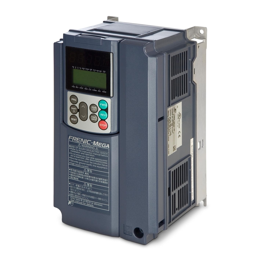
1.2 External View and Terminal Blocks (1) Outside and inside views (a) e.g. FRN020G1S-4U Front cover Cooling fans Front cover fixing screw Wiring guide Sub nameplate Keypad Control circuit terminal block Warning plate Main nameplate Front cover Main circuit terminal block (b) e.g. - Page 23 (2) Warning plates and labels Warning plate Warning plate Warning label Warning label Warning label (on heat sink) Figure 1.3 Warning Plates and Labels...
-
Page 24: Precautions For Using Inverters
Install the inverter in an environment that satisfies the requirements listed in Table 2.1 in Chapter 2. Fuji Electric strongly recommends installing inverters in a panel for safety reasons, in particular, when installing the ones whose enclosure rating is IP00. - Page 25 Storage environment The storage environment in which the inverter is stored after purchase is different from the operation environment. For details, refer to the FRENIC-MEGA User's Manual, Chapter 2. Wiring precautions (1) Route the wiring of the control circuit terminals as far from the wiring of the main circuit as possible. Otherwise electric noise may cause malfunctions.
- Page 26 (2) Power supply lines (Application of a DC/AC reactor) Use an optional DC reactor (DCR) when the capacity of the power supply transformer is 500 kVA or more and is 10 times or more the inverter rated capacity or when there are thyristor-driven loads. If no DCR is used, the percentage-reactance of the power supply decreases, and harmonic components and their peak levels increase.
- Page 27 Nominal applied Rated current of Nominal applied Rated current of motor MCCB and motor MCCB and Power Power HD/MD/ HD/MD/ (HP) RCD/ELCB (A) (HP) RCD/ELCB (A) supply Inverter type supply Inverter type LD mode LD mode voltage voltage Three- Single- Three- Single- w/ DCR w/o DCR...
- Page 28 Noise reduction If noise generated from the inverter affects other devices, or that generated from peripheral equipment causes the inverter to malfunction, follow the basic measures outlined below. (1) If noise generated from the inverter affects the other devices through power wires or grounding wires: - Isolate the grounding terminals of the inverter from those of the other devices.
-
Page 29: Precautions In Running Inverters
Avoid such operation. Synchronous motors It is necessary to take special measures suitable for this motor type. Contact your Fuji Electric representative for details. Single-phase motors Single-phase motors are not suitable for inverter-driven variable speed operation. -
Page 30: Precautions For Use On Single-Phase Power
1.3.4 Precautions for use on single-phase power An inverter is a device that converts alternating current of the input line to direct current via the ac-to-dc rectifier and then converts it to alternating current via the dc-to-ac switching inverter circuit in order to output the required alternating current. The FRENIC-MEGA is designed to connect to the three-phase power and this manual stipulates the specifications for the use on the three-phase power. -
Page 31: Chapter 2 Mounting And Wiring The Inverter
Chapter 2 MOUNTING AND WIRING THE INVERTER 2.1 Operating Environment Install the inverter in an environment that satisfies the requirements listed in Table 2.1. Table 2.1 Environmental Requirements Table 2.2 Output Current Derating Factor in Relation to Altitude Item Specifications Output current Site location Indoors... - Page 32 When employing external cooling In external cooling, the heat sink, which dissipates about 70% of the total heat (total loss) generated into air, is situated outside the equipment or the panel. The external cooling, therefore, significantly reduces heat radiating inside the equipment or panel. To employ external cooling for inverters (except DCR built-in type) of 40 HP or below, use the mounting adapter for external cooling (option);...
- Page 33 Figure 2.3 Changing the Positions of the Top and Bottom Mounting Bases When changing the positions of the top and bottom mounting bases, use only the specified screws. Otherwise, a fire or accident could occur. (3) Mounting notes The FRN007G1H-2/4U through FRN040G1H-2/4U should be mounted with four screws or bolts using screw holes A or B shown below.
-
Page 34: Wiring
2.3 Wiring Follow the procedure below. (In the following description, the inverter has already been installed.) 2.3.1 Removing and mounting the front cover and the wiring guide (1) For inverters of 40 HP or below First loosen the front cover fixing screw, slide the cover downward holding both sides, tilt it toward you, and then pull it upward, as shown below. -
Page 35: Screw Specifications And Recommended Wire Sizes
2.3.2 Screw specifications and recommended wire sizes (1) Arrangement of main circuit terminals The tables and figures given below show the screw specifications and wire sizes. Note that the terminal arrangements differ depending on the inverter types. In each of the figures, two grounding terminals ( G) are not exclusive to the power supply wiring (primary circuit) or motor wiring (secondary circuit). - Page 36 Unit: inch (mm) Refer to Section 2.3.3 (9).
- Page 37 Table 2.6 Recommended Wire Sizes Inverter type Recommended wire size AWG (mm Power supply L1/R, L2/S, Grounding Braking resistor voltage LD mode MD mode HD mode U, V, W L3/T [ G] [P1, P(+)] [P(+), DB] FRNF50G1S-2U FRNF50G1S-2U 14 (2.1) FRN001G1S-2U FRN001G1S-2U 14 (2.1)
-
Page 38: Wiring Precautions
Recommended wire size Terminals common to all inverters Remarks AWG (mm Auxiliary control power input terminals [R0] and [T0] 2 HP or above 14 (2.1) 230 V series with 60 HP or above and Auxiliary fan power input terminals [R1] and [T1] 460 V series with 125 HP or above (2) Arrangement of control circuit terminals (common to all inverter types) Screw size: M3, Tightening torque: 6.2 lb-in (0.7 N·m) - Page 39 Before removal of clip-off sections After removal of clip-off sections Wiring Guide (e.g. FRN025G1S-4U) (8) In some types of inverters, the wires from the main circuit terminal block cannot be routed straight into the terminal. Route such wires as shown below so that the front cover can be reinstalled. (9) For inverters of 900 and 1000 HP, two L2/S input terminals are arranged vertically to the terminal block.
- Page 40 • When wiring the inverter to the power source, insert a recommended molded case circuit breaker (MCCB) or residual-current-operated protective device (RCD)/earth leakage circuit breaker (ELCB) (with overcurrent protection) in the path of each pair of power lines to inverters. Use the recommended devices within the recommended current capacity. •...
-
Page 41: Wiring Of Main Circuit Terminals And Grounding Terminals
2.3.4 Wiring of main circuit terminals and grounding terminals This section shows connection diagrams with the Enable input function used. SINK mode input by factory default 2-11... - Page 42 *1 Install a recommended molded case circuit breaker (MCCB) or residual-current-operated protective device (RCD)/earth leakage circuit breaker (ELCB) (with overcurrent protection function) in the primary circuit of the inverter to protect wiring. Ensure that the circuit breaker capacity is equivalent to or lower than the recommended capacity. *2 Install a magnetic contactor (MC) for each inverter to separate the inverter from the power supply, apart from the MCCB or RCD/ELCB, when necessary.
- Page 43 DC reactor terminals P1 and P(+) Connect a DC reactor (DCR) to these terminals for power factor correction. 1) Remove the jumper bar from terminals P1 and P(+). 2) Connect an optional DCR to those terminals. • The wiring length should be 33 ft (10 m) or below. •...
- Page 44 2) Connecting other external devices A DC link bus of other inverter(s) or a PWM converter is connectable to these terminals. When you need to use the DC link bus terminals P(+) and N(-), consult your Fuji Electric representative. Switching connectors...
- Page 45 Fan power supply switching connectors (CN R and CN W) (on inverters of 60 HP or above for 230 V and those of 125 HP or above for 460 V) The standard FRENIC-MEGA series accepts DC-linked power input in combination with a PWM converter. Inverters of 60 HP or above for 230 V and those of 125 HP or above for 460 V, however, contain AC-driven components such as AC fans.
- Page 46 To remove each of the jumpers, pinch its upper side between your fingers, unlock its fastener, and pull it up. When mounting it, fit the jumper over the connector until it snaps into place. Figure 2.7 Inserting/Removing the Jumpers Main circuit power input terminals L1/R, L2/S, and L3/T (three-phase input) The three-phase input power lines are connected to these terminals.
- Page 47 When connecting a PWM converter with an inverter, do not connect the power supply line directly to terminals R0 and T0. If a PWM is to be connected, insert an isolation transformer or auxiliary B contacts of a magnetic contactor at the power supply side.
-
Page 48: Wiring For Control Circuit Terminals
2.3.5 Wiring for control circuit terminals In general, the insulation of the control signal wires are not specifically designed to withstand a high voltage (i.e., reinforced insulation is not applied). Therefore, if a control signal wire comes into direct contact with a live conductor of the main circuit, the insulation may break down, which would expose the signal wire to the high voltage of the main circuit. - Page 49 Table 2.7 lists the symbols, names and functions of the control circuit terminals. The wiring to the control circuit terminals differs depending upon the setting of the function codes, which reflects the use of the inverter. Route wires properly to reduce the influence of noise.
- Page 50 Table 2.7 Symbols, Names and Functions of the Control Circuit Terminals (Continued) Symbol Name Functions - Since low level analog signals are handled, these signals are especially susceptible to the external noise effects. Route the wiring as short as possible (within 66 ft (20 m)) and use shielded wires. In principle, ground the shielded sheath of wires;...
- Page 51 Table 2.7 Symbols, Names and Functions of the Control Circuit Terminals (Continued) Symbol Name Functions (1) This terminal has the Safe Torque Off (STO) function that is compliant with EN954-1, [EN] Enable input Category 3. It allows the hardware circuit to stop the inverter's output transistors and coast the motor to a stop.
- Page 52 Table 2.7 Symbols, Names and Functions of the Control Circuit Terminals (Continued) Symbol Name Functions Programmable Programmable <Control circuit> <Control circuit> logic controller logic controller SINK [PLC] [PLC] SINK SOURCE SOURCE [X1] to [X7], [X1] to [X7], Photocoupler Photocoupler [FWD], [REV] [FWD], [REV] [CM] [CM]...
- Page 53 Table 2.7 Symbols, Names and Functions of the Control Circuit Terminals (Continued) Symbol Name Functions [Y1] Transistor (1) Various signals such as inverter running, speed/freq. arrival and overload early warning output 1 can be assigned to any terminals, [Y1] to [Y4] by setting function code E20 to E24. Refer to Chapter 5, Section 5.2 "Details of Function Codes"...
- Page 54 Table 2.7 Symbols, Names and Functions of the Control Circuit Terminals (Continued) Symbol Name Functions [30A/B/C] Alarm relay (1) Outputs a contact signal (SPDT) when a protective function has been activated to stop output the motor. (for any error) Contact rating: 250 VAC, 0.3A, cos φ = 0.3, 48 VDC, 0.5A (2) Any one of output signals assigned to terminals [Y1] to [Y4] can also be assigned to this relay contact to use it for signal output.
-
Page 55: Setting Up The Slide Switches
Wiring for control circuit terminals For FRN125G1S-2U, FRN150G1S-2U and FRN250G1S-4U to FRN1000G1S-4U (1) As shown in Figure 2.19, route the control circuit wires along the left side panel to the outside of the inverter. (2) Secure those wires to the wiring support, using a cable tie (e.g., Insulok) with 0.15 inch (3.8 mm) or less in width and 0.059 inch (1.5 mm) or less in thickness. - Page 56 Table 2.8 lists function of each slide switch. Table 2.8 Function of Each Slide Switch Switch Function Switches the service mode of the digital input terminals between SINK and SOURCE. ▪ This switches the input mode of digital input terminals [X1] to [X7], [FWD] and [REV] to be used as the SINK or SOURCE mode.
-
Page 57: Mounting And Connecting The Keypad
2.4 Mounting and Connecting the Keypad The standard keypad TP-G1W-J1 meets UL Type 4 (NEMA4) by itself. On the panel or at a remote site The keypad can be mounted on the panel wall as shown below or installed at a remote site for operation on hand. Mount the keypad with four M3 x 12 screws provided--two fine thread screws and two coarse thread tapping screws. -
Page 58: Chapter 3 Operation Using The Keypad
Chapter 3 OPERATION USING THE KEYPAD 3.1 LED Monitor, LCD Monitor, and Keys The keypad allows you to start and stop the motor, view various data including maintenance information and alarm information, configure function codes, monitor I/O signal status, copy data, and calculate the load factor. 7-segment LED monitor LCD monitor Indicator indexes... - Page 59 Table 3.1 Overview of Keypad Functions (Continued) Item Monitors and Keys Functions Switches the operation modes of the inverter. Shifts the cursor to the right for entry of a numerical value. Pressing this key after removing the cause of an alarm switches the inverter to Running mode. This key is used to reset settings or screen transition.
-
Page 60: Overview Of Operation Modes
Type Item Description (information, condition, and status) Running in the forward rotation Running status Running in the reverse rotation STOP No output frequency Remote mode Local mode Run command COMM Via communications link (RS-485 (standard, optional), fieldbus option) source Jogging mode HAND Via keypad (This item lights also in local mode.) 3.2 Overview of Operation Modes... -
Page 61: Running Mode
3.3 Running Mode 3.3.1 Running or stopping the motor By factory default, pressing the key starts running the motor in the forward direction and pressing the key decelerates the motor to a stop. The key is disabled. Running or stopping the motor with the keypad is enabled only in Running and Programming modes. -
Page 62: Monitoring The Running Status On The Led Monitor
(2) When function code E45 (LCD monitor item selection) is set at "1" The LCD monitor displays the output frequency, output current, and calculated torque in a bar chart. (The upper indicators show the unit of values displayed on the LED monitor as detailed in Section 3.3.2. The lower ones show the running status and run command source.) Output frequency Bar chart... - Page 63 Table 3.4 Items Monitored (Continued) Monitored Items on the Function Example Unit Meaning of Displayed Value Monitor page # LED Monitor code E43 PID command PID command/feedback amount 1*0* - transformed to that of physical value of (Note 1) the object to be controlled (e.g., temperature) PID feedback amount -...
-
Page 64: Monitoring Light Alarms
3.3.3 Monitoring light alarms The FRENIC-MEGA identifies abnormal states in two categories--Alarm and Light alarm. If the former occurs, the inverter l-al immediately trips; if the latter occurs, the appears on the LED monitor and the "L-ALARM" appears blinking in the operation guide area on the LCD monitor, but the inverter continues to run without tripping. -
Page 65: Programming Mode
3.4 Programming Mode Programming mode provides you with these functions--setting and checking function code data, monitoring maintenance information and checking input/output (I/O) signal status. These functions can be easily selected with a menu-driven system. Table 3.5 lists menus available in Programming mode. When the inverter enters Programming mode from the second time on, the menu selected last in Programming mode will be displayed. -
Page 66: Setting Up Function Codes Quickly Using Quick Setup -- Menu #0 "Quick Setup
3.4.1 Setting up function codes quickly using Quick Setup -- Menu #0 "Quick Setup" -- Menu #0 "Quick Setup" in Programming mode quickly displays and sets up a basic set of function codes specified beforehand. Using Menu #10 "User Setting" adds or deletes function codes to/from the set of function codes registered for Quick Setup by default. - Page 67 Basic configuration of screens Figure 3.8 shows the LCD screen transition for Menu #1 "Data Setting." A hierarchy exists among those screens that are shifted in the order of "menu screen," "list of function codes," and "function code data modification screens." On the modification screen of the target function code, you can modify or check its data.
- Page 68 Basic key operation This section gives a description of the basic key operation, following the example of the data changing flow shown below. This example shows how to change F03 data (maximum frequency) from 58.0 Hz to 58.1 Hz. (1) Turn the inverter ON. It automatically enters Running mode. In that mode, press the key to switch to Programming mode and display the menu screen.
-
Page 69: Checking Changed Function Codes -- Menu #2 "Data Checking
3.4.3 Checking changed function codes -- Menu #2 "Data Checking" -- Menu #2 "Data Checking" in Programming mode allows you to check function codes and their data that has been changed. The function codes whose data has been changed from the factory defaults are marked with an asterisk ( ). Select a function code and press the key to view or change its data. - Page 70 Table 3.7 Drive Monitoring Items (Continued) Page # in Item Symbol Description operation guide PID command value The PID command value and PID feedback amount are displayed after conversion to the virtual physical values (e.g., temperature or pressure) of the object to be controlled using function code E40 and E41 data (PID display coefficients A and B).
- Page 71 (3) Press key to establish the desired menu and proceed to a list of monitoring items. ((5) To go back to the menu screen, press key.) Output frequency (before slip compensation) Output frequency (after slip compensation) Output current Output voltage 1/8: Page # in operation guide, means that this page continues to the next page.
-
Page 72: Checking I/O Signal Status -- Menu #4 "I/O Checking
3.4.5 Checking I/O signal status -- Menu #4 "I/O Checking" -- Menu #4 "I/O Checking" in Programming mode allows you to check the I/O states of digital and analog signals. It is used to check the running status during maintenance or test running. Table 3.8 I/O Check Items Page # in Item... - Page 73 Basic key operation (1) Turn the inverter ON. It automatically enters Running mode. In that mode, press the key to switch to Programming mode and display the menu screen. (2) Move the pointer to "4. I/O CHECK" with the keys. (3) Press the key to establish the selected menu and proceed to a list of I/O check items (consisting of several pages).
- Page 74 I/O signals (option) (in hex.) (See Note 2 given below.) Input signal Output signal Pulse rate signal PG pulse rate (option) A/B phase signal from reference PG Z phase signal from reference PG A/B phase signal from slave PG Z phase signal from slave PG Analog I/O signals (option) Input voltage at terminal [32] Input current at terminal [C2]...
-
Page 75: Reading Maintenance Information -- Menu #5 "Maintenance Information
Table 3.9 Hexadecimal Notation Data Displayed Highest digit Lowest digit Input signal (RST) (XR) (XF) [EN] [X7] [X6] [X5] [X4] [X3] [X2] [X1] [REV] [FWD] [30A/ [Y5A Output signal [Y4] [Y3] [Y2] [Y1] B/C] [I16] [I15] [I14] [I13] [I12] [I11] [I10] [I9] [I8] [I7]... - Page 76 Table 3.10 Maintenance Information Items (Continued) Page # in Item Symbol Description operation guide Shows the content of the cumulative time counter of the voltage application to the electrolytic capacitors on the printed circuit boards, which is calculated by multiplying the cumulative time count by the Cumulative run time of coefficient based on the surrounding temperature condition.
- Page 77 Table 3.10 Maintenance Information Items (Continued) Page # in Item Symbol Description operation guide Shows the ROM version of the option connected to the A-port as a ROM version of option 1 4-digit code. Shows the ROM version of the option connected to the B-port as a ROM version of option 2 4-digit code.
- Page 78 Table 3.10 Maintenance Information Items (Continued) Page # in Item Symbol Description operation guide Shows the factor of the latest light alarm as an alarm code. Light alarm (Latest) LALM1 For details, refer to Chapter 6, Section 6.1 "Protective Functions." Shows the factor of the last light alarm as an alarm code.
- Page 79 Basic key operation (1) Turn the inverter ON. It automatically enters Running mode. In that mode, press the key to switch to Programming mode and display the menu screen. (2) Move the pointer to "5. MAINTENANC" with the keys. (3) Press the key to establish the selected menu and proceed to a list of maintenance items (consisting of several pages).
- Page 80 ROM version (option) ROM version of option 1 (A-port) ROM version of option 2 (B-port) ROM version of option 3 (C-port) Temperature inside the inverter Temperature of heat sink Lifetime of DC link bus capacitor (elapsed hours) Life time of DC link bus capacitor (remaining hours) Cumulative run time of motor 1 Cumulative run time of motor 2 Cumulative run time of motor 3...
-
Page 81: Reading Alarm Information -- Menu #6 "Alarm Information
3.4.7 Reading alarm information -- Menu #6 "Alarm Information" -- Menu #6 "Alarm Information" in Programming mode shows the causes of the past four alarms that triggered protective functions, as an alarm code. It is also possible to display the related alarm information on the current inverter conditions detected when the alarm occurred. - Page 82 On the "detailed alarm info screens," you can view the information on the inverter running status at the time an alarm occurred. Table 3.11 lists the alarm information displayed on the LCD monitor. Table 3.11 Alarm Information Items Page # in Item Symbol Description...
- Page 83 Basic key operation (1) Turn the inverter ON. It automatically enters Running mode. In that mode, press the key to switch to Programming mode and display the menu screen. (2) Move the pointer to "6. ALM INF" with the keys. (3) Press the key to establish the selected menu and proceed to a list of alarms that displays alarm history on the past four alarms (alarm code and the number of occurrences for each alarm).
-
Page 84: Viewing Causes Of Alarm -- Menu #7 "Alarm Cause
Input signals on the control circuit terminal block Highlighted when short-circuited; Normal when opened Input signals via communications link Highlighted when 1; Normal when 0 Output signals Highlighted when 1; Normal when 0 Multiple alarm 1 Multiple alarm 2 Error sub-code Detected speed Common operation items To access the target data, switch to the desired page using the... - Page 85 Basic key operation (1) Turn the inverter ON. It automatically enters Running mode. In that mode, press the key to switch to Programming mode and display the menu screen. (2) Move the pointer to "7. ALM CAUSE" with the keys. (3) Press the key to establish the selected menu and proceed to a list of alarms that displays alarm history on the past four alarms (alarm code and the number of occurrences for each alarm).
-
Page 86: Data Copying -- Menu #8 "Data Copying
3.4.9 Data copying -- Menu #8 "Data Copying" -- Menu #8 "Data Copying" in Programming mode provides "Read," "Write," and "Verify," "Check," and "Protect" functions, enabling the following applications. The keypad can hold three sets of function code data in its internal memory to use for three different inverters. - Page 87 Basic configuration of screens Figure 3.19 shows the LCD screen transition for Menu #8 "Data Copying." A hierarchy exists among those screens that are shifted in the order of "menu screen," "list of copy functions," and "memory area selection screen." On the "memory area selection screen,"...
- Page 88 "In progress" screen A bar indicating progress appears in the bottom. Upon completion of reading, the completion screen automatically appears. Completion screen This screen shows that reading has completed successfully. To go back to a list of copy functions, press key.
- Page 89 There is no compatibility between the function code data held in the keypad memory and that in the inverter memory. (Either data may be non-standard or updating performed results in no compatibility. Contact your Fuji Electric representative.) Figure 3.23 Error Screens for "Writing"...
- Page 90 (3) Verify To display this menu screen, press key in Running mode to switch to Programming mode. Move the pointer to "8. DATA COPY" with keys. Press key to establish the selected menu and proceed to a list of copy functions. List of copy functions keys to select VERIFY.
- Page 91 There is no compatibility between the function code data held in the keypad memory and that in the inverter memory. (Either data may be non-standard or updating performed results in no compatibility. Contact your Fuji Electric representative.) Figure 3.25 Error Screen for "Verify"...
- Page 92 If no valid data is stored in the keypad memory, this ERROR screen appears. (See Note below.) Figure 3.27 Error Screen for "Data Checking" If an ERROR screen appears, press the key to reset the error condition. The screen returns to a list of copy functions. (5) Protect Function code data can be protected from unexpected modifications.
-
Page 93: Measuring Load Factor -- Menu #9 "Load Factor Measurement
3.4.10 Measuring load factor -- Menu #9 "Load Factor Measurement" -- Menu #9 "Load Factor Management" in Programming mode is used to measure the maximum output current, the average output current, and the average braking power. Two types of measurement modes are available as listed below. Table 3.13 Measurement Modes Measurement Mode Description... - Page 94 (7) Press key to establish the specified duration and start measurement. Measurement in progress (remaining time displayed) When measurement is in progress, the remaining time is displayed and counting down. Pressing key during measurement forcibly terminates the measurement. When the measurement duration has elapsed, the measurement stops with the results displayed. Measurement completed (The preset measurement duration reverts to the default.) Maximum output current...
- Page 95 Confirmation screen This screen is to confirm whether to start measurement. (6) If OK, press key to switch to standby for measurement. Waiting for run command (On standby for measurement) (7) Wait for a run command to enter. Upon reception of a run command, the measurement starts. If a run command has already been received, this screen will be skipped.
-
Page 96: Changing Function Codes Covered By Quick Setup -- Menu #10 "User Setting
3.4.11 Changing function codes covered by Quick Setup -- Menu #10 "User Setting" -- Menu #10 "User Setting" in Programming mode is used to add or delete function code to/from the set of function codes registered for Quick Setup. Basic key operation (1) Turn the inverter ON. -
Page 97: Helping Debugging For Communication -- Menu #11 "Communication Debugging
3.4.12 Helping debugging for communication -- Menu #11 "Communication Debugging" -- Menu #11 "Communication Debugging" in Programming mode is used to monitor the data of communication-related function codes (S, M, W, X, and Z codes) to help debug programs for communication with host equipment. Basic key operation (1) Turn the inverter ON. -
Page 98: Alarm Mode
3.5 Alarm Mode If an abnormal condition arises so that the protective function is invoked and issues an alarm, then the inverter automatically switches to Alarm mode, displaying the alarm code on the LED monitor and the alarm information on the LCD monitor as shown below. - Page 99 Previous alarm; No. of consecutive occurrences Cause of alarm Operation guide Operation guide Figure 3.36 Switching of Display of Overlapping Alarm History Display of running status information at the time of alarm (Note 1 in Figure 3.37) By pressing the key while an alarm code is displayed, you can view the output frequency, output current, and other data concerning the running status.
-
Page 100: Chapter 4 Running The Motor
Chapter 4 RUNNING THE MOTOR 4.1 Running the Motor for a Test 4.1.1 Test run procedure Make a test run of the motor using the flowchart given below. This chapter describes the test run procedure with motor 1 dedicated function codes that are marked with an asterisk (*). For motors 2 to 4, replace those asterisked function codes with respective motor dedicated ones. -
Page 101: Powering On And Checking
(3) Check for loose terminals, connectors and screws. (4) Check that the motor is separated from mechanical equipment. (5) Make sure that all switches of devices connected to the inverter are turned OFF. Powering on the inverter with any of those switches being ON may cause an unexpected motor operation. -
Page 102: Selecting A Desired Motor Drive Control
The LD/MD-mode inverter is subject to restrictions on the function code data setting range and internal processing as listed below. Function LD mode MD mode HD mode Remarks Name codes DC braking Setting range: Setting range: 0 to 80% F21* (Braking level) 0 to 100% Setting range:... - Page 103 V/f control with slip compensation active Applying any load to an induction motor causes a rotational slip due to the motor characteristics, decreasing the motor rotation. The inverter’s slip compensation function first presumes the slip value of the motor based on the motor torque generated and raises the output frequency to compensate for the decrease in motor rotation.
- Page 104 The final performance should be determined by adjusting the speed control system or other elements with the inverter being connected to the machinery (load). If you have any questions, contact your Fuji Electric representative. Output...
-
Page 105: Function Code Basic Settings < 1
4.1.6 Function code basic settings < 1 > Driving a HP rating motor under the V/f control (F42* = 0 or 2) or dynamic torque vector control (F42* = 1) requires configuring the following basic function codes. (Refer to Figure 4.1 on page 4-1.) Configure the function codes listed below according to the motor ratings and your machinery design values. -
Page 106: Function Code Basic Settings And Tuning < 2
4.1.7 Function code basic settings and tuning < 2 > Under the V/f control (F42* = 0 or 2) or dynamic torque vector control (F42* = 1), any of the following cases requires configuring the basic function codes given below and auto-tuning. (Refer to Figure 4.1 on page 4-1.) - Driving a non-standard motor - Driving a HP rating motor, provided that the wiring distance between the inverter and motor is long or a reactor is connected Configure the function codes listed below according to the motor ratings and your machinery design values. - Page 107 An undervoltage or any other alarm has occurred. If any of these errors occurs, remove the error cause and perform tuning again, or consult your Fuji Electric representative. Do not execute motor tuning with output filter unless the filter is a reactor type only. A tuning error may result if any other type filter is in use.
-
Page 108: Function Code Basic Settings And Tuning < 3
4.1.8 Function code basic settings and tuning < 3 > Driving a motor under vector control without speed sensor (F42* = 5) or with speed sensor (F42*=6) requires auto-tuning. (Refer to Figure 4.1 on page 4-1.) Configure the function codes listed below according to the motor ratings and your machinery design values. For the motor ratings, check the ratings printed on the motor's nameplate. - Page 109 Drive control P04* Motor parameters Select under the Tuning type Tuning data subjected to tuning following conditions No-load current (P06*) Tuning the %R1, %X and Can rotate the motor, Primary resistance (%R1) (P07*) rated slip frequency, with provided that it is safe. Leakage reactance (%X) (P08*) the motor stopped.
- Page 110 Specify motor parameters (the data of P06*, P16* to P23*) by obtaining the appropriate values on the datasheet issued from the motor manufacturer. For details of conversion from data on the datasheet into ones to be entered as function code data, contact your Fuji Electric representative.
- Page 111 An undervoltage or any other alarm has occurred. If any of these errors occurs, remove the error cause and perform tuning again, or consult your Fuji Electric representative. Do not execute motor tuning with output filter unless the filter is a reactor type only. A tuning error may result if any other type filter is in use.
-
Page 112: Function Code Basic Settings < 4
4.1.9 Function code basic settings < 4 > Driving a HP rating motor under V/f control with speed sensor (F42* = 3) or dynamic torque vector control with speed sensor (F42* = 4) requires configuring the following basic function codes. (Refer to Figure 4.1 on page 4-1.) Configure the function codes listed below according to the motor ratings and your machinery design values. -
Page 113: Function Code Basic Settings And Tuning < 5
4.1.10 Function code basic settings and tuning < 5 > Under V/f control with speed sensor (F42* = 3) or dynamic torque vector control with speed sensor (F42* = 4), any of the following cases requires configuring the basic function codes given below and auto-tuning. (Refer to Figure 4.1 on page 4-1.) - Driving a non-standard motor - Driving a HP rating motor, provided that the wiring distance between the inverter and motor is long or a reactor is connected Configure the function codes listed below according to the motor ratings and your machinery design values. - Page 114 (2) Preparation of machinery Perform appropriate preparations on the motor and its load, such as disengaging the coupling from the motor and deactivating the safety devices. (3) Tuning Set function code P04* to "1" or "2" and then press the key as shown below.
-
Page 115: Running The Inverter For Motor Operation Check
If any of these errors occurs, remove the error cause and perform tuning again, or consult your Fuji Electric representative. Do not execute motor tuning with output filter unless the filter is a reactor type only. A tuning error may result if any other type filter is in use. - Page 116 < Modification of motor control function code data > Modifying the current function code data sometimes can solve an insufficient torque or overcurrent incident. The table below lists the major function codes to be accessed. For details, see Chapter 5 "FUNCTION CODES" and Chapter 6 "TROUBLESHOOTING." Drive control Function Name...
-
Page 117: Preparation For Practical Operation
4.1.12 Preparation for practical operation After verifying normal motor running with the inverter in a test run, connect the motor with the machinery and perform wiring for practical operation. (1) Configure the application related function codes that operate the machinery. (2) Check interfacing with the peripheral circuits. -
Page 118: Special Operations
4.2 Special Operations 4.2.1 Jogging (inching) the motor To start jogging operation, perform the following procedure. (1) Making the inverter ready for jogging 1) Switch the inverter to Running mode (see Section 3.2). 2) Press the " keys" simultaneously (when the run command source is "Keypad" (F02 = 0, , or 3). The lower indicator above the "JOG"... -
Page 119: External Run/Frequency Command
The paths of transition between remote and local modes depend on the current mode and the value (ON/OFF) of LOC, the signal giving precedence to the commands from the keypad, as shown in the state transition diagram shown in Figure 4.4. For further details on how to set run commands and frequency commands in remote and local modes, refer to the drive command related section in the User's Manual, "BLOCK DIAGRAMS FOR CONTROL LOGIC."... -
Page 120: Chapter 5 Function Codes
Chapter 5 FUNCTION CODES 5.1 Function Code Tables Function codes enable the FRENIC-MEGA series of inverters to be set up to match your system requirements. Each function code consists of a 3-letter alphanumeric string. The first letter is an alphabet that identifies its group and the following two letters are numerals that identify each individual code in the group. - Page 121 Drive control The FRENIC-MEGA runs under any of the following drive controls. Some function codes apply exclusively to the specific drive control, which is indicated by letters Y (Applicable) and N (Not applicable) in the "Drive control" column in the function code tables given on the following pages.
- Page 122 The following tables list the function codes available for the FRENIC-MEGA series of inverters. F codes: Fundamental Functions Drive control Refer Default Code Name Data setting range setting Torque page: control F00 Data Protection 0: Disable both data protection and digital reference 5-34 protection 1: Enable data protection and disable digital reference...
- Page 123 Drive control Refer Default Code Name Data setting range setting Torque page: control F23 Starting Frequency 1 0.0 to 60.0 Hz 5-59 (Holding time) 0.00 to 10.00 s 0.00 F25 Stop Frequency 0.0 to 60.0 Hz F26 Motor Sound (Carrier frequency) 0.75 to 16 kHz (LD-mode inverters of 0.5 to 30 HP and 5-62 HD-mode ones of 0.5 to 100 HP) 0.75 to 10 kHz (LD-mode inverters of 40 to 100 HP and...
- Page 124 Drive control Refer Default Code Name Data setting range setting Torque page: control F43 Current Limiter (Mode selection) 0: Disable (No current limiter works.) 5-75 1: Enable at constant speed (Disable during ACC/DEC) 2: Enable during ACC/constant speed operation (Level) 20% to 200% (The data is interpreted as the rated output current of the inverter for 100%.) F50 Electronic Thermal Overload 0 (Braking resistor built-in type), 1 to 9000 kWs,...
- Page 125 E codes: Extension Terminal Functions Drive control Refer Default Code Name Data setting range setting Torque page: control Selecting function code data assigns the corresponding 5-79 function to terminals [X1] to [X7] as listed below. E01 Terminal [X1] Function 0 (1000): Select multi-frequency (0 to 1 steps) (SS1) E02 Terminal [X2] Function...
- Page 126 Drive control Refer Default Code Name Data setting range setting Torque page: control E10 Acceleration Time 2 0.00 to 6000 s 5-45 Note: Entering 0.00 cancels the acceleration time, E11 Deceleration Time 2 5-90 requiring external soft-start and -stop. E12 Acceleration Time 3 E13 Deceleration Time 3 E14 Acceleration Time 4 E15 Deceleration Time 4...
- Page 127 Drive control Refer Default Code Name Data setting range setting Torque page: control 70 (1070): Speed valid (DNZS) 5-91 71 (1071): Speed agreement (DSAG) 72 (1072): Frequency (speed) arrival signal 3 (FAR3) 76 (1076): PG error detected (PG-ERR) 82 (1082): Positioning completion signal (PSET) 84 (1084): Maintenance timer (MNT)
- Page 128 Drive control Refer Default Code Name Data setting range setting Torque page: control E50 Coefficient for Speed Indication 0.01 to 200.00 30.00 5-102 E51 Display Coefficient for Input 0.000 (Cancel/reset), 0.001 to 9999 0.010 Watt-hour Data E52 Keypad (Menu display mode) 0: Function code data editing mode (Menus #0, #1, and 1: Function code data check mode (Menus #2 and #7) 2: Full-menu mode E54 Frequency Detection 3...
- Page 129 Drive control Refer Default Code Name Data setting range setting Torque page: control 30 (1030): Force to stop (STOP) 5-79 ((30 = Active OFF, 1030 = Active ON) 5-106 32 (1032): Pre-excitation (EXITE) 33 (1033): Reset PID integral and differential components (PID-RST) 34 (1034): Hold PID integral component...
- Page 130 C codes: Control Functions of Frequency Drive control Refer Default Code Name Data setting range setting Torque page: control C01 Jump Frequency 1 0.0 to 500.0 Hz 5-107 (Hysteresis width) 0.0 to 30.0 Hz C05 Multi-frequency 1 0.00 to 500.00 Hz 0.00 0.00 0.00...
- Page 131 P codes: Motor 1 Parameters Drive control Refer Default Code Name Data setting range setting Torque page: control P01 Motor 1 (No. of poles) 2 to 22 poles Y1 Y2 5-111 (Rated capacity) 0.01 to 1000 kW (when P99 = 0, 2, 3 or 4) Y1 Y2 0.01 to 1000 HP (when P99 = 1) (Rated current) 0.00 to 2000 A...
- Page 132 H codes: High Performance Functions Drive control Refer Default Code Name Data setting range setting Torque page: control H03 Data Initialization 0: Disable initialization 5-116 1: Initialize all function code data to the factory defaults 2: Initialize motor 1 parameters 3: Initialize motor 2 parameters 4: Initialize motor 3 parameters 5: Initialize motor 4 parameters...
- Page 133 Drive control Refer Default Code Name Data setting range setting Torque page: control H49 Starting Mode 0.0 to 10.0 s 5-119 (Auto search delay time 1) 5-127 H50 Non-linear V/f Pattern 1 (Frequency) 0.0: Cancel, 0.1 to 500.0 Hz 5-43 (Voltage) 0 to 240: Output an AVR-controlled voltage 5-127 (for 230 V series)
- Page 134 Drive control Refer Default Code Name Data setting range setting Torque page: control H73 Torque Limiter 0: Enable during ACC/DEC and running at constant 5-66 (Operating conditions) speed 5-129 1: Disable during ACC/DEC and enable during running at constant speed 2: Enable during ACC/DEC and disable during running at constant speed (Control target) 0: Motor-generating torque limit...
- Page 135 A codes: Motor 2 Parameters Drive control Refer Default Code Name Data setting range setting Torque page: control A01 Maximum Frequency 2 25.0 to 500.0 Hz 60.0 ― A02 Base Frequency 2 25.0 to 500.0 Hz 60.0 A03 Rated Voltage at Base Frequency 2 0: Output a voltage in proportion to input voltage 80 to 240: Output an AVR-controlled voltage (for 230 V series)
- Page 136 Drive control Refer Default Code Name Data setting range setting Torque page: control A18 Motor 2 (Auto-tuning) 0: Disable ― 1: Tune while the motor stops. (%R1, %X and rated slip frequency) 2: Tune while the motor is rotating under V/f control (%R1, %X, rated slip frequency, no-load current, magnetic saturation factors 1 to 5, and magnetic saturation extension factors "a"...
- Page 137 b codes: Motor 3 Parameters Drive control Refer Default Code Name Data setting range setting Torque page: control b01 Maximum Frequency 3 25.0 to 500.0 Hz 60.0 ― b02 Base Frequency 3 25.0 to 500.0 Hz 60.0 b03 Rated Voltage at Base Frequency 3 0: Output a voltage in proportion to input voltage 80 to 240: Output an AVR-controlled voltage (for 230 V series)
- Page 138 Drive control Refer Default Code Name Data setting range setting Torque page: control (Iron loss factor 2) 0.00% to 20.00% Y1 Y2 0.00 ― (Iron loss factor 3) 0.00% to 20.00% Y1 Y2 0.00 (Magnetic saturation factor 1) 0.0% to 300.0% Y1 Y2 (Magnetic saturation factor 2) 0.0% to 300.0% Y1 Y2...
- Page 139 r codes: Motor 4 Parameters Drive control Refer Default Code Name Data setting range setting Torque page: control r01 Maximum Frequency 4 25.0 to 500.0 Hz 60.0 ― r02 Base Frequency 4 25.0 to 500.0 Hz 60.0 r03 Rated Voltage at Base Frequency 4 0: Output a voltage in proportion to input voltage 80 to 240: Output an AVR-controlled voltage (for 230 V series)
- Page 140 Drive control Refer Default Code Name Data setting range setting Torque page: control (Iron loss factor 2) 0.00% to 20.00% Y1 Y2 0.00 ― (Iron loss factor 3) 0.00% to 20.00% Y1 Y2 0.00 (Magnetic saturation factor 1) 0.0% to 300.0% Y1 Y2 (Magnetic saturation factor 2) 0.0% to 300.0% Y1 Y2...
- Page 141 J codes: Application Functions 1 Drive control Refer Default Code Name Data setting range setting Torque page: control J01 PID Control (Mode selection) 0: Disable 5-140 1: Enable (Process control, normal operation) 2: Enable (Process control, inverse operation) 3: Enable (Dancer control) (Remote command SV) 0: keys on keypad 5-141...
- Page 142 d codes: Application Functions 2 Drive control Refer Default Code Name Data setting range setting Torque page: control d01 Speed Control 1 0.000 to 5.000 s 0.020 5-159 (Speed command filter) (Speed detection filter) 0.000 to 0.100 s 0.005 P (Gain) 0.1 to 200.0 times 10.0 I (Integral time) 0.001 to 9.999 s 0.100...
- Page 143 Drive control Refer Default Code Name Data setting range setting Torque page: control d71 Synchronous Operation 0.00 to 1.50 times 1.00 5-166 (Main speed regulator gain) (APR P gain) 0.00 to 200.00 times 1500 (APR positive output limiter) 20 to 200%, 999: No limiter (APR negative output limiter) 20 to 200%, 999: No limiter (Z phase alignment gain) 0.00 to 10.00 times 1.00...
- Page 144 U codes: Application Functions 3 Drive control Refer Default Code Name Data setting range setting Torque page: control U00 Customizable Logic (Mode selection) 0: Disable 5-167 1: Enable (Customizable logic operation) U01 Customizable Logic: (Input 1) 0 (1000): Inverter running (RUN) U02 Step 1 (Input 2) 1 (1001):...
- Page 145 Drive control Refer Default Code Name Data setting range setting Torque page: control 84 (1084): Maintenance timer (MNT) 5-167 98 (1098): Light alarm (L-ALM) 99 (1099): Alarm output (for any alarm) (ALM) 101 (1101): Enable circuit failure detected (DECF) 102 (1102): Enable input OFF (EN OFF) 105 (1105): Braking transistor broken (DBAL)
- Page 146 Drive control Refer Default Code Name Data setting range setting Torque page: control U11 Customizable Logic: (Input 1) See U01. See U01. 5-167 U12 Step 3 (Input 2) See U02. See U02. (Logic circuit) See U03. (Type of timer) See U04. (Timer) See U05.
- Page 147 Drive control Refer Default Code Name Data setting range setting Torque page: control U81 Customizable Logic Output Signal 1 0 (1000): Select multi-frequency (0 to 1 step) (SS1) 5-167 (Function selection) 1 (1001): Select multi-frequency (0 to 3 steps) (SS2) U82 Customizable Logic Output Signal 2 2 (1002): Select multi-frequency (0 to 7 steps)
- Page 148 Drive control Refer Default Code Name Data setting range setting page: Torque U91 Customizable Logic Timer Monitor 1: Step 1 5-167 (Step selection) 2: Step 2 3: Step 3 4: Step 4 5: Step 5 6: Step 6 7: Step 7 8: Step 8 9: Step 9 10: Step 10...
- Page 149 y codes: LINK Functions Drive control Refer Default Code Name Data setting range setting Torque page: control y01 RS-485 Communication 1 1 to 255 5-176 (Station address) (Communications error processing) 0: Immediately trip with alarm 1: Trip with alarm after running for the period specified by timer y03 2: Retry during the period specified by timer y03.
- Page 150 Table A Factory Defaults Depending upon Inverter Capacity Auto-restart after Auto-restart after Inverter Inverter momentary power failure momentary power failure capacity capacity 1000 5-31...
- Page 151 Table B Motor Parameters When the "HP rating motors" is selected with P99/A39/b39/r39 (data = 1) Three-phase 230 V series (FRN_ _ _G1 -2U) Note: A box ( ) replaces S or H depending on the enclosure. 5-32...
- Page 152 Table B Motor Parameters (Continued) Three-phase 460 V series (FRN_ _ _G1 -4U) Note: A box ( ) replaces S or H depending on the enclosure. 5-33...
-
Page 153: Details Of Function Codes
5.2 Details of Function Codes This section provides the details of the function codes. The descriptions are, in principle, arranged in the order of function code groups and in numerical order. However, highly relevant function codes are collectively described where one of them first appears. - Page 154 Configuring a reference frequency [ 1 ] Using keys (F01 = 0 (factory default) or 8) (1) Set function code F01 at "0" or "8" ( keys on keypad). This cannot be done when the keypad is in Programming or Alarm mode. To enable frequency setting using the keys, first place the keypad in Running mode.
- Page 155 The table below lists the available command sources and their symbols. Available Command Sources Symbol Command source Symbol Command source Symbol Command source HAND Keypad MULTI Multi-frequency PID-HAND PID keypad command PID command 1 Terminal [12] PID-P1 (Analog command) PID command 2 Terminal [C1] RS485-1 RS-485 (Port 1) *...
- Page 156 Gain and bias If F01 = 3 (the sum of [12] + [C1] is enabled), the bias and gain are independently applied to each of the voltage and current inputs given to terminals [12] and [C1], and the sum of the two values is applied as the reference frequency.
- Page 157 (Point B) To make the maximum frequency equal to the reference frequency for an analog input being at 5 V, set the gain to 100% (C32 = 100). Since 5 V is the gain base point and it is equal to 50% of 10 V (full scale of terminal [12]), set the gain base point to 50% (C34 = 50).
- Page 158 Specifying the initial value for the UP/DOWN control Specify the initial value to start the UP/DOWN control. Data for H61 Initial value to start the UP/DOWN control Mode fixing the value at "0": The inverter automatically clears the value to "0" when restarted (including powered ON). Speed up by the UP command.
- Page 159 [ 4 ] Using pulse train input (F01 = 12) Selecting the pulse train input format (d59) A pulse train in the format selected by the function code d59 can give a frequency command to the inverter. Three types of formats are available;...
- Page 160 Pulse count factor 1 (d62), Pulse count factor 2 (d63) For the pulse train input, function codes d62 (Command (Pulse rate input), (Pulse count factor 1)) and d63 (Command (Pulse rate input), (Pulse count factor 2)) define the relationship between the input pulse rate and the frequency command (reference).
- Page 161 Operation Method F02 selects the source that specifies a run command. Data for F02 Run Command Description Keypad Enables the , and keys to run the motor in the forward and reverse directions, and stop the motor. Terminal command FWD or REV Enables input terminal commands FWD and REV to run the motor in the forward and reverse directions, and stop the motor.
- Page 162 Maximum Frequency 1 F03 specifies the maximum frequency to limit the output frequency. Specifying the maximum frequency exceeding the rating of the equipment driven by the inverter may cause damage or a dangerous situation. Make sure that the maximum frequency setting matches the equipment rating. - Data setting range: 25.0 to 500.0 (Hz) •...
- Page 163 Examples: Normal (linear) V/f pattern V/f pattern with three non-linear points Base Frequency 1 (F04) Data setting range: 25.0 to 500.0 (Hz) Set the rated frequency printed on the nameplate labeled on the motor. F codes Rated Voltage at Base Frequency 1 (F05) Data setting range: 0: Output a voltage in proportion to input voltage (The Automatic Voltage Regulator (AVR) is disabled.) 80 to 240 (V): Output an AVR-controlled voltage for 230 V series...
- Page 164 In vector control, current feedback control is performed. In the current feedback control, the current is controlled with the difference between the motor induced voltage and the inverter output voltage. For a proper control, the inverter output voltage should be sufficiently higher than the motor induced voltage. Generally, the voltage difference is about 20 V for 230 V series, about 40 V for 460 V series.
- Page 165 Under vector control without speed sensor Under vector control with speed sensor Acceleration/deceleration time Function code Acceleration/ Switching factor of acceleration/deceleration time deceleration time Refer to the descriptions of E01 to E07.) ACC time DEC time The combinations of ON/OFF states of the two Acceleration/ terminal commands RT2 and RT1 offer four deceleration time 1...
- Page 166 Acceleration/Deceleration pattern (H07) H07 specifies the acceleration and deceleration patterns (patterns to control output frequency). Acceleration/ Data for Function deceleration Motion code pattern Linear The inverter runs the motor with the constant acceleration and - deceleration. S-curve To reduce an impact that Weak: -...
- Page 167 Curvilinear acceleration/deceleration Acceleration/deceleration is linear below the base frequency (constant torque) but it slows down above the base frequency to maintain a certain level of load factor (constant output). This acceleration/deceleration pattern allows the motor to accelerate or decelerate with its maximum performance. The figures at left show the acceleration characteristics.
- Page 168 Electronic Thermal Overload Protection for Motor 1 F10 to F12 (Select motor characteristics, Overload detection level, and Thermal time constant) F10 through F12 specify the thermal characteristics of the motor for its electronic thermal overload protection that is used to detect overload conditions of the motor.
- Page 169 Nominal Applied Motor and Characteristic Factors when P99 (Motor 1 Selection) = 1 or 3 Reference current Output frequency for Characteristic Nominal applied Thermal time for setting the motor characteristic factor factor (%) motor constant τ thermal time (Factory default) α1 α2 α3...
- Page 170 Restart Mode after Momentary Power Failure (Mode selection) H13 (Restart Mode after Momentary Power Failure (Restart time)) H14 (Restart Mode after Momentary Power Failure (Frequency fall rate)) H15 (Restart Mode after Momentary Power Failure (Continuous running level)) H16 (Restart Mode after Momentary Power Failure (Allowable momentary power failure time)) H92 (Continuity of running (P)) H93 (Continuity of running (I)) F14 specifies the action to be taken by the inverter such as trip and restart in the event of a momentary power failure.
- Page 171 • Under vector control without speed sensor Description Data for F14 Auto search disabled Auto search enabled 0: Trip immediately As soon as the DC link bus voltage drops below the undervoltage detection level due to a momentary power failure, the inverter issues undervoltage alarm and shuts down its output so that the motor enters a coast-to-stop state.
- Page 172 If you enable the "Restart mode after momentary power failure" (Function code F14 = 3, 4, or 5), the inverter automatically restarts the motor running when the power is recovered. Design the machinery or equipment so that human safety is ensured after restarting. Otherwise an accident could occur.
- Page 173 During a momentary power failure, the motor slows down. After power is restored, the inverter restarts at the frequency just before the momentary power failure. Then, the current limiting function works and the output frequency of the inverter automatically decreases. When the output frequency matches the motor speed, the motor accelerates up to the original output frequency.
- Page 174 Restart mode after momentary power failure (Allowable momentary power failure time) (H16) H16 specifies the maximum allowable duration (0.0 to 30.0 seconds) from an occurrence of a momentary power failure (undervoltage) until the inverter is to be restarted. Specify the coast-to-stop time which the machine system and facility can tolerate.
- Page 175 Factory default: By factory default, H13 is set to the value suitable for the standard motor (see Table A in Section 5.1 "Function Code Tables"). Basically, it is not necessary to change H13 data. However, if the long restart time causes the flow rate of the pump to overly decrease or causes any other problem, you might as well reduce the setting to about a half of the default value.
- Page 176 Even if you select "Trip after decelerate-to-stop" or "Continue to run," the inverter may not be able to do so when the load's inertia is small or the load is heavy, due to undervoltage caused by a control delay. In such a case, when "Trip after decelerate-to-stop"...
- Page 177 (Refer to F01.) Bias (Frequency command 1) F20 to F22 DC Braking 1 (Braking starting frequency, Braking level, and Braking time) DC Braking (Braking response mode) F20 through F22 specify the DC braking that prevents motor 1 from running by inertia during decelerate-to-stop operation. If the motor enters a decelerate-to-stop operation by turning OFF the run command or by decreasing the reference frequency below the stop frequency, the inverter activates the DC braking by flowing a current at the braking level (F21) during the braking time (F22) when the output frequency goes down to the DC braking starting frequency (F20).
- Page 178 It is also possible to use an external digital input signal as an "Enable DC braking" terminal command DCBRK. As long as the DCBRK command is ON, the inverter performs DC braking, regardless of the braking time specified by F22. Refer to E01 through E07, data =13.) Turning the DCBRK command ON even when the inverter is in a stopped state activates the DC braking.
- Page 179 Starting frequency 1 (Holding time) (F24) Data setting range: 0.00 to 10.00 (s) F24 specifies the holding time for the starting frequency 1. Stop frequency (F25) Data setting range: 0.0 to 60.0 (Hz) F25 specifies the stop frequency at the stop of the inverter. Under V/f control, even if the stop frequency is set at 0.0 Hz, the inverter stops at 0.1 Hz.
- Page 180 The table below shows the conditions for zero speed control to be enabled or disabled. Speed command Run command Data for d24 Operation ― Stop (Gate OFF) Below the starting and At startup Stop (Gate OFF) stop frequencies Zero speed control ―...
- Page 181 H98 (Protection/Maintenance Function (Mode selection)) F26, F27 Motor Sound (Carrier frequency and Tone) Motor Sound (Carrier frequency) (F26) F26 controls the carrier frequency so as to reduce an audible noise generated by the motor or electromagnetic noise from the inverter itself, and to decrease a leakage current from the main output (secondary) wirings. Item Characteristics Remarks...
- Page 182 F29 to F31 Analog Output [FM1] and [FM2] (Mode selection, Voltage adjustment, Function) F32, F34, These function codes allow terminals [FM1] and [FM2] to output monitored data such as the output frequency and the output current in an analog DC voltage or current. The magnitude of such analog voltage or current is adjustable. Mode selection (F29 and F32) F29 and F32 specify the property of the output to terminals [FM1] and [FM2], respectively.
- Page 183 Data for Function Meter scale [FM1]/[FM2] output F31/F35 (Monitor the following) (Full scale at 100%) Command via communications link Universal AO (Refer to the RS-485 Communication 20000 as 100% User's Manual.) Motor output Motor output (kW) Twice the rated motor output This always outputs the full-scale Calibration (+) Full scale output of the meter calibration...
- Page 184 V/f characteristics The FRENIC-MEGA series of inverters offers a variety of V/f patterns and torque boosts, which include V/f patterns suitable for variable torque load such as general fans and pumps and for constant torque load (including special pumps requiring high starting torque). Two types of torque boosts are available: manual and automatic. Variable torque V/f pattern (F37 = 0) Linear V/f pattern (F37 = 1) When the variable torque V/f pattern is selected (F37 = 0 or 3), the output voltage may be low at a low frequency...
- Page 185 • Auto torque boost If the auto torque boost is selected, the inverter automatically optimizes the output voltage to fit the motor with its load. Under light load, the inverter decreases the output voltage to prevent the motor from over-excitation. Under heavy load, it increases the output voltage to increase the output torque of the motor.
- Page 186 Related function codes Function code Name V/f control Vector control Remarks Torque Limiter 1-1 Torque Limiter 1-2 Torque Limiter 2-1 Torque Limiter 2-2 Torque Limiter (Operating conditions) Torque Limiter (Control target) Torque Limiter (Target quadrants) Torque Limiter (Frequency increment limit for braking) Terminal [12] Extended Function 7: Analog torque limit value A E61 to E63...
- Page 187 Torque limiter levels specified via communications link (S10, S11) The torque limiter levels can be changed via the communications link. Function codes S10 and S11 exclusively reserved for the communications link respond to function codes F40 and F41. Switching torque limiters The torque limiters can be switched by the function code setting and the terminal command TL2/TL1 ("Select torque limiter level 2/1") assigned to any of the digital input terminals.
- Page 188 Under vector control without/with speed sensor If the inverter’s output torque exceeds the specified levels of the torque limiters (F40, F41, E16, E17, and E61 to E63), the inverter controls the speed regulator's output (torque command) in speed control or a torque command in torque control in order to limit the motor-generating torque.
- Page 189 Torque Limiter (Target quadrants) (H75) H75 selects the configuration of target quadrants (Drive/brake, Forward/reverse rotation) in which the specified torque limiter(s) is activated, from "Drive/brake torque limit," "Same torque limit for all four quadrants," and "Upper/lower torque limits" shown in the table below. Data for H75 Target quadrants 0: Drive/brake...
- Page 190 Data for H75 Target quadrants Second quadrant: First quadrant: Reverse braking Forward driving Torque limiter A Torque limiter B Third quadrant: Fourth quadrant: Reverse driving Forward braking Pattern 3 • If the value of torque limiter A is less than that of torque limiter B, torque limiter A applies to both the upper and lower limits.
- Page 191 Torque limiter (Operating conditions) (H73) H73 specifies whether the torque limiter is enabled or disabled during acceleration/deceleration and running at constant speed. Data for H73 During accelerating/decelerating During running at constant speed Enable Enable Disable Enable Enable Disable The torque limiter and current limiter are very similar in function. If both are activated concurrently, they may conflict with each other and cause hunting (undesirable oscillation of the system).
- Page 192 H68 (Slip Compensation 1 (Operating conditions)) Drive Control Selection 1 F42 specifies the motor drive control. Data for Drive control Basic control Speed feedback Speed control V/f control with slip compensation inactive Frequency control Dynamic torque vector control Disable Frequency control (with slip compensation and auto torque boost) with slip compensation V/f control...
- Page 193 V/f control with speed sensor Applying any load to an induction motor causes a rotational slip due to the motor characteristics, decreasing the motor rotation. Under V/f control with speed sensor, the inverter detects the motor rotation using the encoder mounted on the motor shaft and compensates for the decrease in slip frequency by the PI control to match the motor rotation with the reference speed.
- Page 194 H12 (Instantaneous Overcurrent Limiting (Mode selection)) F43, F44 Current Limiter (Mode selection, Level) When the output current of the inverter exceeds the level specified by the current limiter (F44), the inverter automatically manages its output frequency to prevent a stall and limits the output current. The default setting of the current limiter is 130%, 145% and 160% for LD-, MD- and HD-mode inverters, respectively.
- Page 195 FRENIC-MEGA User's Manual, Chapter 4, Section 4.4.1.1 "Braking resistors (DBRs) and braking units." The values listed in the manual are for standard models and 10% ED models of the braking resistors which Fuji Electric provides. When using a braking resistor of any other manufacturer, confirm the corresponding values with the manufacturer, and set the function codes accordingly.
- Page 196 Allowable average loss (F51) The allowable average loss refers to a tolerance for motor continuous operation, which is obtained based on the %ED (%) and motor rated capacity (HP). Data for F51 Function 0.001 to 99.99 0.001 to 99.99 (kW) During deceleration: %ED(%) Motor rated capacity (HP)
- Page 197 The LD/MD-mode inverter is subject to restrictions on the function code data setting range and internal processing as listed below. Function Name LD mode MD mode HD mode Remarks codes DC braking Setting range: F21* Setting range: 0 to 80% (Braking level) 0 to 100% Setting range:...
-
Page 198: E Codes (Extension Terminal Functions)
5.2.2 E codes (Extension Terminal Functions) E98 (Terminal [FWD] Function) E01 to E07 Terminal [X1] to [X7] Function E99 (Terminal [REV] Function) E01 to E07, E98 and E99 assign commands (listed below) to general-purpose, programming, digital input terminals, [X1] to [X7], [FWD], and [REV]. - Page 199 Function code data Drive control Related Terminal commands assigned Symbol Torque function codes Active ON Active OFF control Enable auto search for idling motor 1026 H09, d67 speed at starting 1030 Force to stop F07, H56 STOP 1032 Pre-excitation H84, H85 EXITE Reset PID integral and differential 1033...
- Page 200 Terminal function assignment and data setting Coast to a stop -- BX (Function code data = 7) Turning this terminal command ON immediately shuts down the inverter output so that the motor coasts to a stop without issuing any alarms. Reset alarm -- RST (Function code data = 8) Turning this terminal command ON clears the ALM state--alarm output (for any fault).
- Page 201 Operation Schemes • When the motor speed remains almost the same during coast-to-stop: • When the motor speed decreases significantly during coast-to-stop (with the current limiter activated): • Secure more than 0.1 second after turning ON the "Switch to commercial power" signal before turning ON a run command.
- Page 202 Example of Sequence Circuit Note 1) Emergency switch Manual switch provided for the event that the motor drive source cannot be switched normally to the commercial power due to a serious problem of the inverter Note 2) When any alarm has occurred inside the inverter, the motor drive source will automatically be switched to the commercial power.
- Page 203 Example of Operation Time Scheme Alternatively, you may use the integrated sequence by which some of the actions above are automatically performed by the inverter itself. For details, refer to the description of ISW50 and ISW60 . Cancel PID control -- Hz/PID (Function code data = 20) Turning this terminal command ON disables the PID control.
- Page 204 Switch normal/inverse operation -- IVS (Function code data = 21) This terminal command switches the output frequency control between normal (proportional to the input value) and inverse in analog frequency setting or under PID process control. To select the inverse operation, turn the IVS ON. The normal/inverse switching operation is useful for air-conditioners that require switching between cooling and heating.
- Page 205 Universal DI -- U-DI (Function code data = 25) Using U-DI enables the inverter to monitor digital signals sent from the peripheral equipment via an RS-485 communications link or a fieldbus option by feeding those signals to the digital input terminals. Signals assigned to the universal DI are simply monitored and do not operate the inverter.
- Page 206 Circuit Diagram and Configuration Main Circuit Configuration of Control Circuit Summary of Operation Output Input (Status signal and magnetic contactor) Inverter operation SW52-1 SW52-2 SW88 ISW50 or ISW60 Run command 52-1 52-2 (Commercial power) (Inverter) Timing Scheme Switching from inverter operation to commercial-power operation ISW50 / ISW60 : ON → OFF (1) The inverter output is shut OFF immediately (Power gate IGBT OFF) (2) The inverter primary circuit SW52-1 and the inverter secondary side SW52-2 are turned OFF immediately.
- Page 207 Switching from commercial-power operation to inverter operation ISW50 / ISW60 : OFF → ON (1) The inverter primary circuit SW52-1 is turned ON immediately. (2) The commercial power circuit SW88 is turned OFF immediately. (3) After an elapse of t2 (0.2 sec + time required for the main circuit to get ready) from when SW52-1 is turned ON, the inverter secondary circuit SW52-2 is turned ON.
- Page 208 Examples of Sequence Circuits 1) Standard sequence 2) Sequence with an emergency switching function 5-89...
- Page 209 3) Sequence with an emergency switching function --Part 2 (Automatic switching by the alarm output issued by the inverter) Cancel PG alarm-- PG-CCL (Function code data = 77) When this terminal command is ON, the PG wire break alarm is ignored. Use this terminal command when switching PG wires for switching motors, for example, to prevent it from being detected as PG wire break.
- Page 210 E20 to E23 Terminal [Y1] to [Y4] Function E24, E27 Terminal [Y5A/C] and [30A/B/C] Function (Relay output) E20 through E24 and E27 assign output signals (listed on the next page) to general-purpose, programmable output terminals [Y1], [Y2], [Y3], [Y4], [Y5A/C] and [30A/B/C]. These function codes can also switch the logic system between normal and negative to define how the inverter interprets the ON or OFF state of each terminal.
- Page 211 Function code data Drive control Related function Functions assigned Symbol codes/signals Torque Active ON Active OFF (data) control 1028 Heat sink overheat early warning ⎯ (See the PG Interface Card 1029 Synchronization completed instruction manual.) 1030 Lifetime alarm (See Section 7.3.) LIFE 1031 Frequency (speed) detected 2...
- Page 212 Inverter running -- RUN (Function code data = 0) Inverter output on -- RUN2 (Function code data = 35) These output signals tell the external equipment that the inverter is running at a starting frequency or higher. If assigned in negative logic (Active OFF), these signals can be used to tell the "Inverter being stopped" state. Output signal Basic function Remarks...
- Page 213 Universal DO -- U-DO (Function code data = 27) Assigning this output signal to an inverter's output terminal and connecting the terminal to a digital input terminal of peripheral equipment via the RS-485 communications link or the fieldbus, allows the inverter to send commands to the peripheral equipment.
- Page 214 Running forward -- FRUN (Function code data = 52) Running reverse -- RRUN (Function code data = 53) Output signal Assigned data Running forward Running reverse Inverter stopped FRUN RRUN In remote operation -- RMT (Function code data = 54) This output signal comes ON when the inverter switches from local to remote mode.
- Page 215 Frequency Arrival (Hysteresis width) E30 specifies the detection level (hysteresis width) for the "Frequency (speed) arrival signal" FAR and the "Frequency (speed) arrival signal 3" FAR3 . Data assigned to Output signal Operating condition 1 Operating condition 2 output terminal Frequency (speed) FAR always goes OFF when the run arrival signal...
- Page 216 E34, E35 Overload Early Warning/Current Detection (Level and Timer) E37, F38 (Current Detection 2/Low Current Detection (Level and Timer)) E55, E56 (Current Detection 3 (Level and Timer)) These function codes define the detection level and time for the "Motor overload early warning" OL , "Current detected" ID , "Current detected 2"...
- Page 217 (Refer to E31.) Frequency Detection 2 (Refer to E34.) E37, E38 Current Detection 2/Low Current Detection (Level and Timer) E40, E41 PID Display Coefficient A, B These function codes specify PID display coefficients A and B to convert a PID command (process command or dancer position command) and its feedback into mnemonic physical quantities to display.
- Page 218 Display coefficients for PID dancer position command and its feedback (J01 = 3) Under PID dancer control, the PID command and its feedback operate within the range ± 100%, so specify the value at +100% of the PID dancer position command or its feedback as coefficient A with E40, and the value at -100% as coefficient B with E41.
- Page 219 E48 (LED Monitor (Speed monitor item)) LED Monitor (Item selection) E43 specifies the running status item to be monitored and displayed on the LED monitor. Specifying the speed monitor with E43 provides a choice of speed-monitoring formats selectable with E48 (LED Monitor). Display sample Function Monitor item...
- Page 220 LED Monitor (Display when stopped) E44 specifies whether the specified value (data = 0) or the output value (data = 1) to be displayed on the LED monitor of the keypad when the inverter is stopped. The monitored item depends on the E48 (LED monitor, Speed monitor item) setting as shown below.
- Page 221 LCD Monitor (Language selection) E46 specifies the language to display on the keypad (TP-G1W-J1) as follows: Data for E46 Language Japanese English German French Spanish Italian LCD Monitor (Contrast control) E47 adjusts the contrast of the LCD monitor on the keypad as follows: Data for E47 0, 1, 2, 3, 4, 5, 6, 7, 8, 9, 10 Contrast...
- Page 222 The menus available on the remote keypad TP-E1U (option) are described below LED monitor Menu # Menu Main functions shows: Displays only basic function codes to customize the inverter *fn: "Quick Setup" operation. !f__ F codes (Fundamental functions) !e__ E codes (Extension terminal functions) !c__ C codes (Control functions) !p__...
- Page 223 E61 to E63 Terminal [12] Extended Function Terminal [C1] Extended Function Terminal [V2] Extended Function E61, E62, and E63 define the function of the terminals [12], [C1], and [V2], respectively. There is no need to set up these terminals if they are to be used for frequency command sources. Data for E61, Input assigned to Description...
- Page 224 Reference Loss Detection (Continuous running frequency) When the analog frequency command (setting through terminal [12], [C1], or [V2]) has dropped below 10% of the reference frequency within 400 ms, the inverter presumes that the analog frequency command wire has been broken and continues its operation at the frequency determined by the ratio specified by E65 to the reference frequency.
- Page 225 Torque detected 1 -- TD1 , Torque detected 2 -- TD2 The output signal TD1 or TD2 comes ON when the torque value calculated by the inverter or torque command exceeds the level specified by E78 or E80 (Torque detection (Level)) for the period specified by E79 or E81 (Torque detection (Timer)), respectively.
-
Page 226: C Codes (Control Functions)
5.2.3 C codes (Control functions) C01 to C03 Jump Frequency 1, 2 and 3 Jump Frequency (Hysteresis width) These function codes enable the inverter to jump over three different points on the output frequency in order to skip resonance caused by the motor speed and natural frequency of the driven machinery (load). - While you are increasing the reference frequency, the moment the reference frequency reaches the bottom of the jump frequency band, the inverter keeps the output at that bottom frequency. - Page 227 Multi-frequency 1 to 15 (C05 through C19) Data setting range: 0.00 to 500.00 (Hz) The combination of SS1 , SS2 , SS4 and SS8 and the selected frequencies are as follows. Selected frequency command Other than multi-frequency * C05 (multi-frequency 1) C06 (multi-frequency 2) C07 (multi-frequency 3) C08 (multi-frequency 4)
- Page 228 H54, H55 (Acceleration/Deceleration Time, Jogging) Jogging Frequency d09 to d13 (Speed Control (Jogging)) To jog or inch the motor for positioning a workpiece, specify the jogging conditions using the jogging-related function codes (C20, H54, H55, and d09 through d13) beforehand, make the inverter ready for jogging, and then enter a run command. Making the inverter ready for jogging Turning ON the "Ready for jogging"...
- Page 229 Offset (C31, C36, C41) Data setting range: -5.0 to +5.0 (%) C31, C36 or C41 configures an offset for an analog voltage/current input. The offset also applies to signals sent from the external equipment. Filter time constant (C33, C38, C43) Data setting range: 0.00 to 5.00 (s) C33, C38 or C43 configures a filter time constant for an analog voltage/current input.
-
Page 230: P Codes (Motor 1 Parameters)
5.2.4 P codes (Motor 1 Parameters) The FRENIC-MEGA drives the motor under V/f control, dynamic torque vector control, V/f control with speed sensor, dynamic torque vector control with speed sensor, vector control without speed sensor, or vector control with speed sensor, which can be selected with function codes. - Page 231 Motor 1 (Auto-tuning) The inverter automatically detects the motor parameters and saves them in its internal memory. Basically, it is not necessary to perform tuning when using a HP rating motor with a standard connection with the inverter. There are three types of auto-tuning as listed below. Select appropriate one considering the limitations in your equipment and control mode.
- Page 232 Motor 1 (Online tuning) Long run under "Dynamic torque vector control" or "Slip compensation control" causes motor temperature change, varying the motor parameters. This changes the motor speed compensation amount, resulting in motor speed deviation from the initial rpm. Enabling online tuning (P05 = 1) identifies motor parameters covering the motor temperature change to decrease the motor speed fluctuation.
- Page 233 (P09, P11 > 100%) may cause hunting (undesirable oscillation of the system), so carefully check the operation on the actual machine. P10 determines the response time for slip compensation. Basically, there is no need to modify the default setting. If you need to modify it, consult your Fuji Electric representatives. Function codes Operation (Slip compensation) Slip compensation gain for driving Adjust the slip compensation amount for driving.
- Page 234 P53, P54 Motor 1 (%X correction factors 1 and 2) P53 and P54 specify the factors to correct fluctuations of leakage reactance (%X). Basically, there is no need to modify the setting. Motor 1 (Torque current under vector control) P55 specifies the rated torque current under vector control without/with speed sensor. The combination of P99 (Motor 1 selection) and P02 (Motor 1 rated capacity) data determines the standard value.
-
Page 235: H Codes (High Performance Functions)
5.2.5 H codes (High Performance Functions) Data Initialization H03 initializes the current function code data to the factory defaults or initializes the motor parameters. To change the H03 data, it is necessary to press the keys or keys (simultaneous keying). Data for H03 Function Disable initialization (Settings manually made by the user will be retained.) - Page 236 H04, H05 Auto Reset (Times and Reset interval) H04 and H05 specify the auto-reset function that makes the inverter automatically attempt to reset the tripped state and restart without issuing an alarm output (for any alarm) even if any protective function subject to reset is activated and the inverter enters the forced-to-stop state (tripped state).
- Page 237 • In the figure below, the inverter failed to restart normal operation within the number of reset times specified by H04 (in this case, 3 times (H04 = 3)), and issued the alarm output (for any alarm) ALM . Auto-resetting -- TRY (E20 to E24 and E27, data = 26) This output signal comes ON when auto-resetting (resetting alarms automatically) is in progress.
- Page 238 H49 (Starting Mode, Auto search delay time 1) Starting Mode (Auto search) H46 (Starting Mode, Auto search delay time 2) Starting Mode (Auto search) H09 specifies the starting mode--whether to enable the auto search for idling motor speed to run the idling motor without stopping it.
- Page 239 Starting Mode (Auto search delay time 1) (H49) Data setting range: 0.0 to 10.0 (s) Auto search for the idling motor speed will become unsuccessful if it is done while the motor retains residual voltage. It is, therefore, necessary to leave the motor for an enough time for residual voltage to disappear. H49 specifies that time (0.0 to 10.0 sec.).
- Page 240 d32, d33 (Torque Control, Speed limits 1 and 2) Torque Control (Mode selection) When vector control with/without speed sensor is selected, the inverter can control the motor-generating torque according to a torque command sent from external sources. Torque Control (Mode selection) (H18) H18 specifies whether to enable or disable the torque control.
- Page 241 Running/stopping the motor Under torque control, the inverter does not control the speed, so it does not perform acceleration or deceleration by soft-start and stop (acceleration/deceleration time) at the time of startup and stop. Turning ON a run command starts the inverter to run and output the commanded torque. Turning it OFF stops the inverter so that the motor coasts to a stop.
- Page 242 Suppose that the internal resistance of the PTC thermistor at the alarm temperature is Rp, the detection level (voltage) V calculated by the expression below. Set the result V to function code H27. 10.5 × 27000 Connect the PTC thermistor as shown below. The voltage obtained by dividing the input voltage on terminal [C1] with a set of internal resistors is compared with the detection level voltage specified by H27.
- Page 243 y98 (Bus Link Function, Mode selection) Communications Link Function (Mode selection) Using the RS-485 communications link (standard/option) or fieldbus (option) allows you to issue frequency commands and run commands from a computer or PLC at a remote location, as well as monitor the inverter running information and the function code data.
- Page 244 Combination of command sources Frequency command Via RS-485 Via RS-485 Via fieldbus Inverter itself communications communications (option) link (port 1) link (port 2) H30 = 0 H30 = 1 H30=4 H30=0 (1 or 4) Inverter itself y98 = 0 y98 = 0 y98=0 y98=1 Via RS-485 communications...
- Page 245 H44, H78 Startup Counter for Motor 1, Maintenance Interval (M1) H79, H94 Preset Startup Count for Maintenance (M1), Cumulative Motor Run Time 1 Cumulative motor run time 1 (H94) Operating the keypad can display the cumulative run time of the 1st motor. This feature is useful for management and maintenance of the machinery.
- Page 246 • If the maintenance interval counter reaches the specified value, set a new value for the next maintenance in H78 and press the key to reset the output signal and restart counting. This function is exclusively applied to the 1st motor. •...
- Page 247 H76 (Torque Limiter, Frequency increment limit for braking) Automatic Deceleration (Mode selection) H69 enables or disables the anti-regenerative control. In the inverter not equipped with a PWM converter or braking unit, if the regenerative energy returned exceeds the inverter's braking capability, an overvoltage trip occurs. To avoid such an overvoltage trip, enable the automatic deceleration (anti-regenerative control) with this function code, and the inverter controls the output frequency to keep the braking torque around "0"...
- Page 248 Overload Prevention Control H70 specifies the decelerating rate of the output frequency to prevent a trip from occurring due to an overload. This control decreases the output frequency of the inverter before the inverter trips due to a heat sink overheat or inverter overload (with an alarm indication of , respectively).
- Page 249 Service Life of DC Link Bus Capacitor (Remaining time) H77 displays the remaining time before the service life of DC link bus capacitor expires. At the time of a printed circuit board replacement, transfer the service life data of the DC link bus capacitor to the new board.
- Page 250 Code Name Description It is judged that the service life of any one of the capacitors (DC link bus capacitors and electrolytic capacitors on the printed circuit boards) and cooling fan has expired. Lifetime alarm Or, failure of the air circulation DC fan inside the inverter. 230 V series: 75 HP or above 460 V series: 125 HP or above Reference command loss detected...
- Page 251 Table 5.3 Display of Light Alarm Factor (Example) Light alarm factors "RS-485 communications error (COM port 2)," "RS-485 communications error (COM port 1)," "Option communications error," "Overload of motor 1" and "Heat sink overheat" are selected by H81. LED No. LED4 LED3 LED2...
- Page 252 H84, H85 Pre-excitation (Initial level, Time) A motor generates torque with magnetic flux and torque current. Lag elements of the rising edge of magnetic flux causes a phenomenon in which enough torque is not generated at the moment of the motor start. To obtain enough torque even at the moment of motor start, enable the pre-excitation with H84 and H85 so that magnetic flux is established before a motor start.
- Page 253 H86 to H90 Reserved for particular manufacturers H86 to H90 are reserved for particular manufacturers. Do not modify the settings. PID Feedback Wire Break Detection Using the terminal [C1] (current input) for PID feedback signal enables wire break detection and alarm ( ) issuance.
- Page 254 Protection/Maintenance Function (Mode selection) H98 specifies whether to enable or disable automatic lowering of carrier frequency, input phase loss protection, output phase loss protection, judgment threshold on the life of DC link bus capacitor, judgment on the life of DC link bus capacitor, DC fan lock detection, braking transistor error detection, and IP20/IP40 switching, in combination (Bit 0 to Bit 7).
- Page 255 Note that, operating the inverter under the condition that the DC fan is locked for long time may shorten the life of electrolytic capacitors on the PCBs due to local high temperature inside the inverter. Be sure to check with the LIFE signal etc., and replace the broken fan as soon as possible.
- Page 256 5.2.6 A codes (Motor 2 Parameters), b codes (Motor 3 Parameters), r codes (Motor 4 Parameters) The FRENIC-MEGA can switch control parameters even when it is running so that a single inverter can drive four motors by switching them or turn the energy saving operation ON or OFF for the setup change (e.g., gear switching) that causes the moment of inertia of the machinery to change.
- Page 257 Table 5.5 Function Codes to be Switched Function code Object of Name parameter switching motor motor motor motor Maximum frequency Base frequency Rated voltage at base frequency Maximum output voltage Torque boost Electronic thermal overload protection for motor (Select motor characteristics) (Overload detection level) (Thermal time constant) DC braking...
- Page 258 Table 5.5 Function Codes to be Switched (Continued) Object of Function code Name parameter motor motor motor motor switching Speed control (Speed command filter) (Speed detection filter) P (Gain) I (Integral time) (Output filter) (Notch filter resonance frequency) (Notch filter attenuation level) Cumulative motor run time Startup counter for motor Motor...
- Page 259 5.2.7 J codes (Application Functions 1) PID Control (Mode selection) Under PID control, the inverter detects the state of a control target object with a sensor or the similar device and compares it with the commanded value (e.g., temperature control command). If there is any deviation between them, the PID control operates so as to minimize it.
- Page 260 Using J01 enables switching between normal and inverse operations against the PID control output, so you can specify an increase/decrease of the motor rotating speed to the difference (error component) between the commanded (input) and feedback amounts, making it possible to apply the inverter to air conditioners. The terminal command IVS can also switch operation between normal and inverse.
- Page 261 [ 1 ] PID command with the keys on the keypad (J02 = 0, factory default) Configuring the PID command (PID process command or PID dancer position command) with the keys (1) To enable PID process control, set function code J01 at "1" or "2." To enable PID dancer control, set function code J01 at "3."...
- Page 262 PID Command Manually Specified with Keys and Requirements PID control PID control LED monitor Multi-frequency Display during key operation (Remote command SV) (Mode selection) SS4, SS8 PID process command by keypad 1 or 2 Other than 0 PID process command currently selected Other than 0 ON or OFF PID dancer position command by keypad...
- Page 263 Gain and bias (Example) Mapping the range of 1 through 5 V at terminal [12] to 0 through 100% [ 3 ] PID command with UP/DOWN control (J02 = 3) When the UP/DOWN control is selected as a PID command, turning the terminal command UP or DOWN ON causes the PID command to change within the range from 0 to 100%.
- Page 264 Selecting Feedback Terminals For feedback control, determine the connection terminal according to the type of the sensor output. • If the sensor is a current output type, use the current input terminal [C1] of the inverter. • If the sensor is a voltage output type, use the voltage input terminal [12] of the inverter, or switch over the terminal [V2] to the voltage input terminal and use it.
- Page 265 Example 2. When the output level of the external sensor is 0 to 10 VDC: • Use terminal [12] since the connection terminal is for voltage input. • When the external sensor's output is of unipolar, the inverter controls the speed within the range of 0 to 100%. In this example, it is recommended that the dancer reference position be set around the +5 V (50%) point.
- Page 266 I (Integral) action An operation in which the change rate of the MV (manipulated value: output frequency) is proportional to the integral value of deviation is called I action, which outputs the MV that integrates the deviation. Therefore, I action is effective in bringing the feedback amount close to the commanded value.
- Page 267 (3) PID control PID control is implemented by combining P action with the deviation suppression of I action and the oscillation suppression of D action. PID control features minimal control deviation, high precision and high stability. In particular, PID control is effective to a system that has a long response time to the occurrence of deviation. Follow the procedure below to set data to PID control function codes.
- Page 268 J08, J09 PID Control (Pressurization starting frequency, pressurizing time) J15 (PID Control, Stop frequency for slow flowrate) J16 (PID Control, Slow flowrate level stop latency) J17 (PID Control, Starting frequency) Slow flowrate stopping function (J15 to J17) J15 to J17 configure the slow flowrate stopping function in pump control, a function that stops the inverter when the discharge pressure rises, causing the volume of water to decrease.
- Page 269 Pressurization before slow flowrate stopping (J08 and J09) Specifying J08 (Pressurization starting frequency) and J09 (Pressurizing time) enables pressurization control when the frequency drops below the level specified by J15 (Stop frequency for slow flowrate) for the period specified by J16. During the pressurization, the PID control is in the hold state.
- Page 270 J11 to J13 PID Control (Select alarm output, Upper level alarm (AH) and Lower level alarm (AL)) The inverter can output two types of alarm signals (absolute-value and deviation alarms) associated with PID control if the digital output signal PID-ALM is assigned to any of the programmable, output terminals with any of E20 through E24 and E27 (data = 42).
- Page 271 Upper level alarm (AH) and lower level alarm (AL) also apply to the following alarms. How to handle the alarm: Alarm Description Select alarm output (J11) Parameter setting Upper limit (absolute) ON when AH < PV Absolute-value alarm J13 (AL) = 0 Lower limit (absolute) ON when PV <...
- Page 272 (Refer to E01 through E07.) Commercial Power Switching Sequence PID Control (Speed command filter) (Refer to J02.) PID Control (Dancer reference position) J57 specifies the dancer reference position in the range of -100% to +100% for dancer control. If J02 = 0 (keypad), this function code is enabled as the dancer reference position. It is also possible to modify the PID command with the keys.
- Page 273 J68 to J70 Brake Signal (Brake-OFF current, Brake-OFF frequency/speed and Brake-OFF timer) J71, J72 Brake Signal (Brake-ON frequency/speed and Brake-ON timer) J95, J96 Brake Signal (Brake-OFF torque and Speed condition selection) These function codes are for the brake releasing/turning-on signals of vertical carrier machines. It is possible to set the conditions of the brake releasing/turning-on signals (current, frequency or torque) so that a hoisted load does not fall down at the start or stop of the operation, or so that the load applied to the brake is reduced.
- Page 274 This operation reduces the load applied to the brake, extending lifetime of the brake. Function Name Data setting range Remarks code Brake-ON frequency/speed 0.0 to 25.0 Hz Brake-ON timer 0.0 to 5.0 s Speed condition selection Criteria of speed condition for brake-ON Specifies the criteria of speed to be used (Braking conditions) (Bit 0)
- Page 275 Operation time chart under vector control without speed sensor Operation time chart under vector control with speed sensor • If the zero speed control is enabled under vector control, set J95 (Brake-OFF torque) at 0%. • After releasing the brake ( BRKS ON), operating for a while, and then activating the brake ( BRKS OFF) to stop the motor, if you want to release the brake ( BRKS ON), turn the inverter's run command OFF and then ON.
- Page 276 J97 to J99 Servo-lock (Gain, Completion timer, Completion range) Servo-lock This function servo-locks the inverter to hold the motor within the positioning completion range specified by J99 for the period specified by J98 even if an external force applies to the load. When the inverter is servo-locked, it keeps the output frequency low;...
- Page 277 Monitor for servo-lock control Monitor item LCD monitor Function code Remarks Current position pulse Only when the positioning device Menu #3 Current position Upper digit: Z90 is in operation (positioning "3: OPR MNTR," Page 8, "P4" Lower digit: Z91 control is active), the LED monitor displays these data.
-
Page 278: D Codes (Application Functions 2)
5.2.8 d codes (Application Functions 2) d01 to d04 Speed Control 1 (Speed command filter, Speed detection filter, P (Gain) and I (Integral time)) Speed Control 1 (Output filter) These function codes control the speed control sequence for normal operations. For application of each function code, refer to the figure below and the subsequent descriptions. - Page 279 Speed Control 1 (Notch filter resonance frequency) Speed Control 1 (Notch filter attenuation level) A49, b49, r49 (Speed control 2 to 4, Notch filter resonance frequency) A50, b50, r50 (Speed control 2 to 4, Notch filter attenuation level) These function codes specify speed control using notch filters. The notch filters make it possible to decrease the speed loop gain only in the vicinity of the predetermined resonance points, suppressing the mechanical resonance.
- Page 280 d14 to d17 Feedback Input (Pulse input format, Encoder pulse resolution, Pulse count factor 1 and Pulse count factor 2) These function codes specify the speed feedback input under vector control with speed sensor. Feedback Input, Pulse input format (d14) d14 specifies the speed feedback input format.
- Page 281 Listed below are expressions for conversion between a speed feedback input pulse rate and motor shaft speed. Pulse count factor 2 (d17) × Encoder shaft speed Motor shaft speed = Pulse count factor 1 (d16) Pulse count factor 2 (d17) ×...
- Page 282 Enabling an operation limiting function such as the torque limit and droop control will increase the deviation caused by a huge gap between the reference speed and detected one. In this case, the inverter may trip interpreting this situation as a PG error, depending on the running state. To avoid this incident, set the d23 data to "0" (Continue to run) to prevent the inverter from tripping even if any of those limiting functions is activated.
- Page 283 Machinery configuration of a winder system and function code settings Shown below is a typical machinery configuration of a winder system for which it is necessary to configure the function codes as listed below. Winder (The radius of the take-up roll increases as the roll rotates.) Radius of take-up roll (r Speed v...
- Page 284 Adjustment Like usual speed controls, it is necessary to adjust the speed command filter, speed detection filter, P gain, and integral time in the speed control sequence that controls the peripheral speed at a constant level. Function code Name Key points Speed control If an excessive overshoot occurs for a speed command change, (Speed command filter)
- Page 285 Command (Pulse Rate Input) (Encoder pulse resolution) d71 to d78 Synchronous Operation These function codes specify various parameters required for synchronous operation. For details, refer to the PG Interface Card instruction manual. Speed Control Limiter d70 specifies a limiter for the PI value output calculated in speed control sequence under V/f control with speed sensor or dynamic torque vector control with speed sensor.
-
Page 286: U Codes (Application Functions 3)
5.2.9 U codes (Application functions 3) Customizable Logic (Mode selection) U01 to U50 Customizable Logic: Step 1 to 10 (Setting) U71 to U75 Customizable Logic Output Signal 1 to 5 (Output selection) U81 to U85 Customizable Logic Output Signal 1 to 5 (Function selection) Customizable Logic Timer Monitor (Step selection) The customizable logic function allows the user to form a logic circuit for digital input/output signals, customize those signals arbitrarily, and configure a simple relay sequence inside the inverter. - Page 287 Block diagram Customizable Logic (Mode selection) (U00) F codes U00 specifies whether to enable the sequence configured with the customizable logic function or disable it to run the inverter only via its input terminals and others. E codes Data for U00 Function C codes Disable...
- Page 288 Configuration of function codes for each step General-purpose Step No. Input 1 Input 2 Logic circuit Time setting Output (Note) timer Step 1 SO01 Step 2 SO02 Step 3 SO03 Step 4 SO04 Step 5 SO05 Step 6 SO06 Step 7 SO07 Step 8 SO08...
- Page 289 Data Selectable Signals Under anti-regenerative control 6005 (7005) REGA (ON under anti-regenerative control) Within dancer reference position 6006 (7006) DR_REF (ON when the dancer roll position is within the reference range) Alarm factor presence 6007 (7007) ALM_ACT (ON when there is no alarm factor) Logic circuit (U03, etc.) Any of the following functions is selectable as a logic circuit (with general-purpose timer).
- Page 290 The block diagrams for individual functions are given below. (1) Through output (2) AND (3) OR General-purpose timer Output Input 1 Input 1 Input 1 General-purpose timer General-purpose timer Output Output Input 2 Input 2 Input 2 (4) XOR (5) Set priority flip-flop General-purpose timer Previous Input 1 Input 2...
- Page 291 (13) Timer with reset input ON timer Input 1 Input 1 Output Input 2 Reset Output Input 2 Timer Timer period General-purpose timer (U04, etc.) The table below lists the general-purpose timers available. Data Function Description No timer On-delay timer Turning an input signal ON starts the on-delay timer.
- Page 292 (5) Pulse train output Input Output Timer Timer period Time setting (U05, etc.) U05 and other related function codes specify the general-purpose timer period or the increment/decrement counter value. Data Function Description The period is specified by seconds. Timer period 0.00 to 600.00 The specified value is multiplied by 100 times.
- Page 293 Function Default Name Data setting range code setting Customizable logic output signal 1 0: Disable (Output selection) 1: Output of step 1, SO01 2: Output of step 2, SO02 Customizable logic output signal 2 (Output selection) 3: Output of step 3, SO03 4: Output of step 4, SO04 Customizable logic output signal 3 (Output selection)
- Page 294 Customizable logic timer monitor (Step selection) (U91) The contents of the timer in a customizable logic can be monitored using the monitor-related function code or the keypad. Selecting a timer to be monitored Function code Function Remarks 1 to 10 U91 specifies the step number whose timer or counter is to be monitored Monitoring...
-
Page 295: Y Codes (Link Functions)
5.2.10 y codes (Link Functions) y01 to y20 RS-485 Communication 1 and 2 Up to two ports of RS-485 communications link are available as listed below. Port Route Function code Applicable equipment Keypad RS-485 communications link Port 1 y01 through y10 FRENIC Loader (via the RJ-45 connector prepared for keypad connection) Host equipment... - Page 296 Communications error processing (y02 for port 1 and y12 for port 2) y02 or y12 specifies the error processing to be performed if an RS-485 communications error occurs. RS-485 communications errors include logical errors (such as address error, parity error, framing error), transmission protocol error, and physical errors (such as no-response error specified by y08 and y18).
- Page 297 Stop bits (y07 for port 1 and y17 for port 2) y07 or y17 specifies the number of stop bits. Data for y07 and y17 Stop bit(s) 2 bits For FRENIC Loader, no setting is required since Loader automatically sets 1 bit. 1 bit For the Modbus RTU protocol, no setting is required since the stop bits are automatically determined associated with the...
- Page 298 Communication Data Storage Selection A nonvolatile storage in the inverter has a limited number of rewritable times (100,000 to 1,000,000 times). Saving data into the storage so many times unnecessarily will no longer allow the storage to save data, causing memory errors. For frequent data writing via the communications link, therefore, a temporary storage is provided instead of the nonvolatile storage.
-
Page 299: Chapter 6 Troubleshooting
Chapter 6 TROUBLESHOOTING 6.1 Protective Functions The FRENIC-MEGA series of inverters has various protective functions as listed below to prevent the system from going down and reduce system downtime. The protective functions marked with an asterisk (*) in the table are disabled by default. Enable them according to your needs. - Page 300 Table 6.1 Abnormal States Detectable ("Alarm" and "Light Alarm" Objects) "Alarm" "Light alarm" Code Name Remarks Ref. page objects objects √ 0c3 Instantaneous overcurrent 6-12 √ Ground fault 50 HP or above 6-12 √ 0u3 Overvoltage 6-12 √ Undervoltage 6-13 √...
- Page 301 Table 6.1 Abnormal States Detectable ("Alarm" and "Light Alarm" Objects) (Continued) "Alarm" "Light alarm" Code Name Remarks Ref. page objects objects l-al Light alarm 75 HP or above for 230 V series √ DC fan locked 125 HP or above for 460 V series √...
-
Page 302: Before Proceeding With Troubleshooting
"light alarm" indication ( ) is displayed For problems that could be caused by running the inverter on single-phase power Go to Section 6.7. If any problems persist after the above recovery procedure, contact your Fuji Electric representative. -
Page 303: Abnormal Motor Operation
l-al 6.3 If Neither an Alarm Code Nor "Light Alarm" Indication ( ) Appears on the LED Monitor This section describes the troubleshooting procedure based on function codes dedicated to motor 1 which are marked with an asterisk (*). For motors 2 to 4, replace those asterisked function codes with respective motor dedicated ones (refer to Chapter 5, Section 5.2.6, Table 5.5). - Page 304 Possible Causes What to Check and Suggested Measures (8) A frequency command with Check the higher priority run command with Menu #2 "Data Checking" and Menu #4 higher priority than the one "I/O Checking" using the keypad, referring to the block diagram of the frequency attempted was active.
- Page 305 Possible Causes What to Check and Suggested Measures (5) The acceleration time was too Check the data of function codes F07, E10, E12, and E14 (Acceleration time). long or too short. Change the acceleration time to match the load. (6) Overload. Measure the output current.
- Page 306 Possible Causes What to Check and Suggested Measures (3) Frequency switching or Check whether the relay signal for switching the frequency command is chattering. multi-frequency command was If the relay contact is defective, replace the relay. enabled. (4) The wiring length between the Check whether auto-torque boost, auto-energy saving operation, or dynamic torque inverter and the motor is too vector control is enabled.
- Page 307 [ 6 ] The motor does not accelerate or decelerate within the specified time. Possible Causes What to Check and Suggested Measures (1) The inverter runs the motor Check the data of function code H07 (Acceleration/deceleration pattern). with S-curve or curvilinear Select the linear pattern (H07 = 0).
- Page 308 [ 8 ] The motor abnormally heats up. Possible Causes What to Check and Suggested Measures (1) Excessive torque boost Check whether decreasing the torque boost (F09*) decreases the output current but does specified. not stall the motor. If no stall occurs, decrease the torque boost (F09*). (2) Continuous running in Check the running speed of the inverter.
-
Page 309: Problems With Inverter Settings
6.3.2 Problems with inverter settings [ 1 ] Nothing appears on the LED monitor. Possible Causes What to Check and Suggested Measures (1) No power (neither main power Check the input voltage and interphase voltage unbalance. nor auxiliary control power) Turn ON a molded case circuit breaker (MCCB), a residual-current- supplied to the inverter. -
Page 310: If An Alarm Code Appears On The Led Monitor
6.4 If an Alarm Code Appears on the LED Monitor [ 1 ] Instantaneous overcurrent Problem The inverter momentary output current exceeded the overcurrent level. Overcurrent occurred during acceleration. Overcurrent occurred during deceleration. Overcurrent occurred during running at a constant speed. Possible Causes What to Check and Suggested Measures (1) The inverter output lines were... - Page 311 Possible Causes What to Check and Suggested Measures (2) A surge current entered the In the same power line, if a phase-advancing capacitor is turned ON/OFF or a thyristor input power supply. converter is activated, a surge (momentary large increase in the voltage or current) may be caused in the input power.
- Page 312 [ 5 ] Input phase loss Problem Input phase loss occurred, or interphase voltage unbalance rate was large. Possible Causes What to Check and Suggested Measures (1) Breaks in wiring to the main Measure the input voltage. power input terminals. Repair or replace the main circuit power input wires or input devices (MCCB, MC, etc.).
- Page 313 Possible Causes What to Check and Suggested Measures (3) Cooling fan's airflow volume Check the cumulative run time of the cooling fan. Refer to Chapter 3, Section 3.4.6 decreased due to the service life "Reading maintenance information – Menu #5 "Maintenance Information"." expired or failure.
- Page 314 [ 10 ] Motor protection (PTC/NTC thermistor) Problem Temperature of the motor has risen abnormally. Possible Causes What to Check and Suggested Measures (1) The temperature around the Measure the temperature around the motor. motor exceeded the motor's Lower the temperature. specification range.
- Page 315 [ 12 ] Fuse blown Problem The fuse inside the inverter blew. Possible Causes What to Check and Suggested Measures (1) The fuse blew due to Check whether there has been any excess surge or noise coming from outside. short-circuiting inside the Take measures against surges and noise.
- Page 316 [ 15 ] Inverter overload Problem Temperature inside inverter has risen abnormally. Possible Causes What to Check and Suggested Measures (1) Temperature around the Measure the temperature around the inverter. inverter exceeded the inverter's Lower the temperature (e.g., ventilate the panel where the inverter is mounted). specification range.
- Page 317 [ 17 ] PG wire break Problem The pulse generator (PG) wire has been broken somewhere in the circuit. Possible Causes What to Check and Suggested Measures (1) The wire between the pulse Check whether the pulse generator (PG) is correctly connected to the option card or any generator (PG) and the option wire is broken.
- Page 318 [ 20 ] CPU error Problem A CPU error (e.g. erratic CPU operation) occurred. Possible Causes What to Check and Suggested Measures (1) Inverter affected by strong Check if appropriate noise control measures have been implemented (e.g. correct electrical noise. grounding and routing of signal wires, communications cables, and main circuit wires).
- Page 319 [ 24 ] Tuning error Problem Auto-tuning failed. Possible Causes What to Check and Suggested Measures (1) A phase was missing (There Properly connect the motor to the inverter. was a phase loss) in the connection between the inverter and the motor. (2) V/f or the rated current of the Check whether the data of function codes (F04*, F05*, H50 through H53, H65, H66, motor was not properly set.
- Page 320 (1) The inverter capacity setting on It is necessary to set the inverter capacity correctly. the control printed circuit board Contact your Fuji Electric representative. is wrong. (2) Data stored in the power It is necessary to replace the power printed circuit board.
- Page 321 Possible Causes What to Check and Suggested Measures (3) The motor speed does not rise Check the data of function code F44 (Current limiter (Level)). due to the current limiter Change the F44 data correctly. Or, set the F43 data to "0" (Disable) if the current operation.
- Page 322 Check whether resistance of the braking resistor is correct or there is a misconnection of broken. the resistor. Consult your Fuji Electric representative for repair. [ 33 ] Positioning control error (Servo-lock) Problem An excessive positioning deviation has occurred when the servo-lock function was activated.
-
Page 323: If The "Light Alarm" Indication ( L-Al ) Appears On The Led Monitor
l-al 6.5 If the "Light Alarm" Indication ( ) Appears on the LED Monitor If the inverter detects a minor abnormal state "light alarm," it can continue the current operation without tripping while displaying l-al l-al the "light alarm" indication on the LED monitor. -
Page 324: If An Abnormal Pattern Appears On The Led Monitor Except Alarm Codes And "Light Alarm" Indication ( L-Al )
6.6 If an Abnormal Pattern Appears on the LED Monitor except Alarm Codes and "Light Alarm" l-al Indication ( [ 1 ] – – – – (center bar) appears Problem A center bar (– – – –) appeared on the LED monitor. Possible Causes What to Check and Suggested Measures (1) When PID control had been... -
Page 325: If The Inverter Is Running On Single-Phase Power
6.7 If the Inverter is Running on Single-Phase Power [ 1 ] The AC fan(s) does not work. (230 V series with 60 HP or above or 460 V series with 125 HP or above) Possible Causes Suggested Measures The power supply is connected to the Connect the power supply to L1 and L3. -
Page 326: Chapter 7 Maintenance And Inspection
Chapter 7 MAINTENANCE AND INSPECTION Perform daily and periodic inspections to avoid trouble and keep the reliability of the inverter at its maximum. When performing inspections, follow the instructions given in this chapter. • Before proceeding to the maintenance/inspection jobs, turn OFF the power and wait at least five minutes for inverters of 40 HP or below, or at least ten minutes for inverters of 50 HP or above. - Page 327 Table 7.1 List of Periodic Inspections (Continued) Check part Check item How to inspect Evaluation criteria 1) Check that bolts and screws are tight and not 1) Retighten. 1), 2), 3) Common missing. No abnormalities 2) Check the devices and insulators for 2), 3) deformation, cracks, breakage and Visual inspection...
-
Page 328: List Of Periodic Replacement Parts
Each part of the inverter has its own service life that will vary according to the environmental and operating conditions. It is recommended that the following parts be replaced at the specified intervals. When the replacement is necessary, consult your Fuji Electric representative. Table 7.2 Replacement Parts Part name Standard replacement intervals (See Note below.) - Page 329 Notes for the judgment on the service life of the DC link bus capacitor The service life of the DC link bus capacitor can be judged by the "measurement of discharging time" or "ON-time counting." Measurement of discharging time - The discharging time of the DC link bus capacitor depends largely on the inverter's internal load conditions, e.g. options attached or ON/OFF of digital I/O signals.
- Page 330 5) The inverter automatically starts the measurement of the capacitance of the DC link bus capacitor. Make sure that " .." appears on the LED monitor. If " .." does not appear on the LED monitor, the measurement has not started. Check the conditions listed in 1). 6) After "...
-
Page 331: Measurement Of Electrical Amounts In Main Circuit
7.4 Measurement of Electrical Amounts in Main Circuit Because the voltage and current of the power supply (input, primary circuit) of the main circuit of the inverter and those of the motor (output, secondary circuit) contain harmonic components, the readings may vary with the type of the meter. Use meters indicated in Table 7.4 when measuring with meters for commercial frequencies. -
Page 332: Insulation Test
Disconnect all the wiring connected to the inverter so that the test voltage is not applied to the inverter. 7.6 Inquiries about Product and Guarantee 7.6.1 When making an inquiry Upon breakage of the product, uncertainties, failure or inquiries, inform your Fuji Electric representative of the following information. 1) Inverter type (Refer to Chapter 1, Section 1.1.) 2) SER No. -
Page 333: Product Warranty
2) However, in cases where the use environment, conditions of use, use frequency and times used, etc., have an effect on product life, this warranty period may not apply. 3) Furthermore, the warranty period for parts restored by Fuji Electric's Service Department is ''6 months from the date that repairs are completed.''... - Page 334 [ 2 ] Exclusion of liability for loss of opportunity, etc. Regardless of whether a breakdown occurs during or after the free of charge warranty period, this company shall not be liable for any loss of opportunity, loss of profits, or damages arising from special circumstances, secondary damages, accident compensation to another company, or damages to products other than this company's products, whether foreseen or not by this company, which this company is not be responsible for causing.
-
Page 335: Chapter 8 Specifications
Chapter 8 SPECIFICATIONS 8.1 Standard Model 1 (Basic Type) 8.1.1 Three-phase 230 V series LD (Low Duty)-mode inverters for light load Item Specifications Type (FRN_ _ _G1S-2U) Nominal applied motor (HP) (Output rating) Rated capacity (kVA) Three-phase 200 to 230 V Rated voltage (V) Three-phase 200 to 240 V (with AVR function) (with AVR function) -
Page 336: Three-Phase 460 V Series
8.1.2 Three-phase 460 V series LD (Low Duty)-mode inverters for light load (0.5 to 100 HP) Item Specifications Type (FRN_ _ _G1S-4U) Nominal applied motor (HP) (Output rating) Rated capacity (kVA) 13.1 18.3 Rated voltage (V) Three-phase 380 to 480 V (with AVR function) Rated current (A) 13.5 16.5... - Page 337 MD (Medium Duty)-mode inverters for medium load (150 to 700 HP) Item Specifications Type (FRN_ _ _G1S-4U) 150 Nominal applied motor (HP) (Output rating) Rated capacity (kVA) Rated voltage (V) Three-phase 380 to 480 V (with AVR function) Rated current (A) Overload capability 150%-1 min 380 to 440 V, 50 Hz...
- Page 338 HD (High Duty)-mode inverters for heavy load (0.5 to 75 HP) Item Specifications Type (FRN_ _ _G1S-4U) Nominal applied motor (HP) (Output rating) Rated capacity (kVA) Rated voltage (V) Three-phase 380 to 480 V (with AVR function) Rated current (A) 13.5 13.5 18.5...
-
Page 339: Standard Model 2 (Dcr Built-In Type)
8.2 Standard Model 2 (DCR Built-in Type) 8.2.1 Three-phase 230 V series LD (Low Duty)-mode inverters for light load Item Specifications Type (FRN_ _ _G1H-2U) Nominal applied motor (HP) (Output rating) Rated capacity (kVA) Three-phase 200 to 230 V Rated voltage (V) Three-phase 200 to 240 V (with AVR function) (with AVR function) 31.8... -
Page 340: Three-Phase 460 V Series
8.2.2 Three-phase 460 V series LD (Low Duty)-mode inverters for light load Item Specifications Type (FRN_ _ _G1H-4U) Nominal applied motor (HP) (Output rating) Rated capacity (kVA) 13.1 18.3 Rated voltage (V) Three-phase 380 to 480 V (with AVR function) Rated current (A) 13.5 16.5... -
Page 341: Common Specifications
8.3 Common Specifications Item Explanation Maximum frequency 25 to 500 Hz (120 Hz for inverters in LD/MD mode) (120 Hz under vector control without speed sensor) (200 Hz under V/f control with speed sensor or vector control with speed sensor) Base frequency 25 to 500 Hz (in conjunction with the maximum frequency) Starting frequency... - Page 342 Item Explanation Frequency command • Keypad: keys • Analog input (Analog input can be set with external voltage/current input): 0 to ± 10 VDC/0 to ± 100% (terminals [12], [V2]) +4 to +20 mA DC/0 to 100% (terminal [C1]) • UP/DOWN operation: Multi-frequency (16 steps), 16-bit parallel •...
- Page 343 Item Explanation Terminals [FM1] and [FM2]: Analog output Output a selected signal with analog DC voltage (0 to +10 V) or analog DC current (4 to 20 mA) Selectable output signals: Output frequency (before slip compensation, after slip compensation), output current, output voltage, output torque, load factor, input power, PID feedback amount, speed (PG feedback value), DC link bus voltage, universal AO, motor output, calibration, PID command (SV), PID output (MV)
-
Page 344: External Dimensions
8.4 External Dimensions 8.4.1 Standard models 40 HP or below Inverter type Dimensions inch (mm) FRN_ _ _G1S-2U/4U ØA 230 V 460 V W1 W2 0.75 4.33 3.78 (132) (19) (110) (96) 0.24 9.69 0.28 4.45 0.12 0.24 (246) (113) 5.71 1.26 5.91... -
Page 345: Panel Cutting Of Standard Model (50 Hp Or Above)
8.4.2 Panel cutting of standard model (50 HP or above) Inverter type Dimensions FRN_ _ _G1S-2U/4U inch (mm) Refer to: 230V 460V 12.28 11.34 9.45 20.87 20.16 (312) (288) (240) (530) (512) 23.43 22.72 (595) (577) 12.72 0.35 (323) 25.79 25.08 13.66 10.83... -
Page 346: Dc Reactor (Dcr)
8.4.3 DC reactor (DCR) Dimensions inch (mm) Power Inverter type Option/ Refer Mass supply FRN_ _ _G1S Reactor Mounting Terminal Standard lb (kg) voltage -2U/4U hole hole 0.59 0.04 DCR2-0.4 (15) 3.54 2.83 0.2×0.31 0.06 DCR2-0.75 (66) (56) (90) (72) (94) (5.2×8) (1.4) - Page 347 Dimensions inch (mm) Power Inverter type Option/ Refer Mass supply FRN_ _ _G1S Reactor Mounting Terminal Standard lb (kg) voltage -2U/4U hole hole 0.59 0.04 DCR4-0.4 (15) 3.54 2.83 0.2×0.31 0.06 DCR4-0.75 (66) (56) (90) (72) (94) (5.2×8) (1.4) 0.79 (20) 0.06 DCR4-1.5...
- Page 348 Figure A Figure B Figure C Figure D Terminal hole Mounting Mounting hole hole 2 x 4 x Terminal hole Figure E Mounting hole DCR4-630C: 2 x 2 x Terminal hole DCR4-710C: 2 x 4 x Terminal hole 8-14...
-
Page 349: Dcr Built-In Type
8.4.4 DCR built-in type Inverter type Dimensions inch (mm) FRN_ _ _G1H-2U/4U Mounting Mounting hole hole 230 V 460 V W4 W5 W6 φA1 φA2 5.49 8.66 1.59 1.59 7.72 4.17 12.6 10.24 1.18 9.37 11.7 0.43 (220) (40.3) (40.3) (196) (106) (320) -
Page 350: Standard Models With Nama1 Kit (Option)
8.4.5 Standard models with NEMA1 kit (option) Inverter type Dimensions 40 HP or below FRN_ _ _G1S-2U/4U inch (mm) 230 V 460 V 5.26 (133.5) 4.45 (113) 5.76 (146.3) 12.2 (310) 5.87 5.76 (149) (146.2) 8.66 13.24 (220) (336.2) 7.68 (195) 19.27 (490) -
Page 351: Keypad (Tp-G1W-J1)
8.4.6 Keypad (TP-G1W-J1) Drill four screw holes and cut a square hole in a panel as specified below. Location of Screw Holes in Panel (viewed from back) Dimensions of Panel Cutting 8-17... -
Page 352: Chapter 9 Conformity With Standards
Chapter 9 CONFORMITY WITH STANDARDS 9.1 Compliance with UL Standards and Canadian Standards (cUL certification) 9.1.1 General Originally, the UL standards were established by Underwriters Laboratories, Inc. as private criteria for inspections/investigations pertaining to fire/accident insurance in the USA. Later, these standards were authorized as the official standards to protect operators, service personnel and the general populace from fires and other accidents in the USA. -
Page 353: Recommended Installation Procedure
9.3.2 Recommended installation procedure To make the machinery or equipment fully compliant with the EMC Directive, have certified technicians wire the motor and inverter in strict accordance with the procedure described below. In case an EMC-compliant filter (optional) is externally used 1) Mount the inverter and the filter on a grounded panel or metal plate. -
Page 354: Compliance With En954-1, Category 3
9.4 Compliance with EN954-1, Category 3 9.4.1 General In FRENIC-MEGA series of inverters, opening the hardware circuit between terminals [EN] and [PLC] stops the output transistor, coasting the motor to a stop. (EN: Enable input) This is the Safe Torque Off (STO) on prescribed in EN60204-1, Category 0 (Uncontrolled stop) and compliant with EN954-1, Category 3. -
Page 355: En954-1
(2) Note for Safe Torque Off (STO) - When configuring the product safety system with this Safe Torque Off (STO), make a risk assessment of not only the external equipment and wiring connected to terminal [EN] but also the whole system including other equipment, devices and wiring against the product safety system required by the machinery manufacturer under the manufacturer's responsibility in order to confirm that the whole system conforms to the product safety system required by the machinery manufacturer. - Page 356 MEMO...
- Page 357 FRENIC-MEGA series of inverters. Please feel free to send your comments regarding any errors or omissions you may have found, or any suggestions you may have for generally improving the manual. In no event will Fuji Electric Corp. of America be liable for any direct or indirect damages resulting from the application of the information in this manual.
- Page 358 Fuji Electric Co., Ltd. Fuji Electric Corp. of America http://www.fujielectric.com/fecoa 2011-04 (D11/D10)
Need help?
Do you have a question about the FRENIC MEGA and is the answer not in the manual?
Questions and answers