Motorola AP-6521 Series Installation Manual
Hide thumbs
Also See for AP-6521 Series:
- Installation manual (56 pages) ,
- Reference manual (954 pages)
Table of Contents
Advertisement
Advertisement
Table of Contents

Related Manuals for Motorola AP-6521 Series


Summary of Contents for Motorola AP-6521 Series
- Page 1 AP-6521 Access Point INSTALLATION GUIDE...
- Page 2 AP-6521 Access Point MOTOROLA SOLUTIONS and the Stylized M Logo are registered in the US Patent & Trademark Office. © Motorola Solutions, Inc. 2013. All rights reserved.
-
Page 3: Table Of Contents
1.4 AP-6521 Package Contents........ - Page 4 5.18 Other Countries..........39 6.0 Motorola Solutions Support Center ....... . . 42...
-
Page 5: Introduction
802.11n Access Point, installed in minutes anywhere a CAT-5e (or better) cable is located. An AP-6521 Series Access Point utilizes a setup wizard to define its operational mode as either a Dependent mode AP, Standalone AP or Virtual Controller AP. -
Page 6: Document Conventions
• Prepare Ethernet port connections. • Verify cabling is within the maximum 100 meter allowable length. 1.4 AP-6521 Package Contents An AP-6521 Access Point is available in integrated antenna and external antenna models. Contents differ depending on the model ordered. • AP-6521 Access Point •... -
Page 7: Features
• Clips for suspended T-Bar mounting • DC power connector An AP-6521 Series Access Point has one RJ-45 connector supporting an 10/100/1000 Ethernet port connection and requires 802.3af compliant power from an external source. The Access Point contains runtime firmware which enables the unit to boot after either a power up or a watchdog... -
Page 8: Hardware Installation
2.1 Installation Instructions An AP-6521 Series Access Point can attach to a wall, mount under a suspended T-Bar or mount above a ceiling. Select a mounting option based on the physical environment of the coverage area. Do not mount the Access Point in a location that has not been approved in a site survey. -
Page 9: Access Point Placement
Access Point. 2.3.1 Antenna Options Motorola Solutions supports two antenna suites for the single radio, dual-band AP-6521 Access Point. One antenna suite supporting the 2.4 GHz band, and another antenna suite supporting the 5 GHz band. Select an antenna best... - Page 10 ML-2452-PNA5-01R Panel ML-2452-PTA3M3-36 Patch ML-5299-PTA1-0R Patch Internal Antenna PIFA For a more exhaustive overview of the antennas and associated components supported by the Motorola Solutions Access Point family, refer to the Enterprise Wireless LAN Antenna Specification Guide available at http://supportcentral.motorolasolutions.com/support/product/manuals.do.
-
Page 11: Power Injector System
Installation Guide 2.3.2 Power Injector System The Access Point can receive power via an Ethernet cable connected to the GE1/PoE port. When users purchase a WLAN solution, they often need to place Access Points in obscure locations. In the past, a dedicated power source was required for each Access Point in addition to the Ethernet infrastructure. - Page 12 Power Injector is placed as close as possible to the Ethernet switch. This will allow the AP-6521 to be deployed away from power drops. • Ensure the cable length from the Ethernet source (host) to the Power Injector and AP-6521 Access Point does not exceed 100 meters (333 ft).
-
Page 13: Wall Mount Installation
9. Cable the Access Point using either the Power Injector solution or an approved line cord and power supply. For Motorola Power Injector installations: a. Connect an RJ-45 CAT5 Ethernet cable between the network data supply (host) and the Power Injector’s Data In connector. -
Page 14: Suspended Ceiling T-Bar Installation
Point is complete. Ensure PoE is not connected to the Access Point’s console connector or risk rendering the console connector permanently inoperable. For Motorola Power Injector installations: a. Connect an RJ-45 CAT5 Ethernet cable between the network data supply (host) and the Power Injector’s Data In connector. - Page 15 Installation Guide 6. Align the bottom of the ceiling T-bar with the back of the Access Point. 7. Orient the Access Point chassis by its length and the length of the ceiling T-bar. 8. Rotate the Access Point chassis 45 degrees clockwise. 9.
-
Page 16: Above The Ceiling (Plenum) Installation
4. Create a light pipe path hole in the target position on the ceiling tile. 5. Use a drill to make a hole in the tile the approximate size of the Access Point LED light pipe. Motorola Solutions recommends care be taken not to damage the CAUTION finished surface of the ceiling tile when creating the light pipe hole and installing the light pipe. - Page 17 Point is complete. Ensure PoE is not connected to the Access Point’s console connector or risk rendering the console connector permanently inoperable. For Motorola Power Injector installations: a. Connect an RJ-45 CAT5 Ethernet cable between the network data supply (host) and the Power Injector’s Data In connector.
-
Page 18: Led Indicator
AP-6521 Access Point 2.7 LED Indicator An AP-6521 Access Point has a single LED activity indicator on the front of the unit. The LED provides a status display indicating error conditions, transmission, and network activity for the 5 GHz 802.11a/n (amber) radio or the 2.4 GHz 802.11b/g/n (green) radio. -
Page 19: Basic Access Point Configuration
Installation Guide Basic Access Point Configuration Once the Access Point is installed and powered on, complete the following steps to get the device up and running and access management functions: 1. Attach an Ethernet cable from the Access Point to a controller with an 802.3af compatible power source or use the PWRS-14000-148R power supply to supply power to the Access Point (once fully cabled). - Page 20 AP-6521 Access Point 3. Enter the default username admin in the Username field. 4. Enter the default password motorola in the Password field. 5. Click the Login button to load the management interface. 6. If this is the first time the management interface has been accessed, the Initial Setup Wizard automatically displays.
- Page 21 Installation Guide The Initial Setup Wizard displays the same pages and content for each NOTE Access Point model supported. The only difference being the number of radios configurable by model, as an AP7131 model can support up to three radios, AP6522, AP6532, AP6562, AP8132 and AP7161 models support two radios and AP6511 and AP6521 models support a single radio.
- Page 22 AP-6521 Access Point 7. Select Save/Commit within each page to save the updates made to that page's configuration. Select Next to proceed to the next page listed in the Navigation Panel without saving your updates. While you can navigate to any page in the navigation panel, you cannot...
- Page 23 UI to connect to the Access Point, provision its configuration and administrate the Access Point’s configuration. If designating the Access Point as a Standalone AP, Motorola Solutions NOTE recommends the Access Point’s UI be used exclusively to define its device configuration, and not the CLI.
- Page 24 AP-6521 Access Point 13. The Typical Setup Wizard displays the Network Topology screen to define how the Access Point handles network traffic. 14. Select an Access Point Mode from the available options. • Router Mode -In Router Mode, the Access Point routes traffic between the local network (LAN) and the Internet or external network (WAN).
- Page 25 Installation Guide 15. Select Next. The Typical Setup Wizard displays the LAN Configuration screen to set the Access Point's LAN interface configuration. 16. Set the following DHCP and Static IP Address/Subnet information for the LAN interface: • Use DHCP - Select the checkbox to enable an automatic network address configuration using the Access Point’s DHCP server.
- Page 26 AP-6521 Access Point • DNS Forwarding - Select this option to allow a DNS server to translate domain names into IP addresses. If this option is not selected, a primary and secondary DNS resource must be specified. DNS forwarding is useful when a request for a domain name is made but the DNS server, responsible for converting the name into its corresponding IP address, cannot locate the matching IP address.
- Page 27 Installation Guide 19. Select Next. The Typical Setup Wizard displays the RADIUS Server Configuration screen if required. Otherwise, the Typical Setup Wizard displays the Summary and Commit screen. 20. Use the Radius Server Configuration screen to configure the users for the onboard RADIUS server. Use the screen to add, modify and remove RADIUS users.
- Page 28 AP-6521 Access Point 21. Select Add User to display the dialog to enter user information to add to the RADIUS server user database. 22. Enter the following user information: • Username - Provide a user name used to authenticate the user.
- Page 29 Installation Guide 27. To dismiss the dialog without adding, modifying or removing entries in the RADIUS server database, select Cancel. 28. Select Next. The Typical Setup Wizard displays the Summary and Commit screen to summarize the screens (pages) and settings updated using the Typical Setup Wizard. No user intervention or additional settings are required.
-
Page 30: Specifications
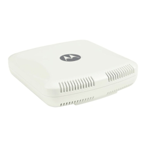
AP-6521 Access Point Specifications 4.1 Electrical Characteristics An AP-6521 model Access Point has the following electrical characteristics: Max DC Power 12.95W (270mA@48V) Consumption 4.2 Physical Characteristics An AP-6521 model Access Point has the following physical characteristics: Dimensions 6.0 (Length) x 5.5 (Width) x 1.63 (Tall) - Inches 152.4 (Length) x 139.7 (Width) x 41.1 (Tall) - Millimeters... -
Page 31: Radio Characteristics
Installation Guide 4.3 Radio Characteristics An AP-6521 model Access Points have the following radio characteristics: Operating Channel (2.4 GHz) Channel 1 to 13 (2412 to 2472 MHz) *Japan Only - Channel 14 (2484 MHz) Operating Channel (5. GHz) Channels 36 - 165 802.11a Data Rates... -
Page 32: Regulatory Information
This guide applies to Part Numbers AP-6521-60010-US, AP-6521-60020-US, AP-6521-60010-WR and AP-6521-60020-WR. AP-6521 Series Access Points are approved under MODEL: NCAP-500. All Motorola/Symbol devices are designed to be compliant with rules and regulations in locations they are sold and will be labeled as required. -
Page 33: Frequency Of Operation - Fcc And Ic
Installation Guide 5.2.2 Frequency of Operation – FCC and IC 5 GHz Only The use on UNII (Unlicensed National Information Infrastructure) Band 1 5150-5250 MHz is restricted to indoor use only, any other use will make the operation of this device illegal. Industry Canada Statement: Caution: The device for the band 5150-5250 MHz is only for indoor usage to reduce potential for harmful interference to co-Channel mobile satellite systems. -
Page 34: Rf Exposure Guidelines
Only operate the device in accordance with the instructions supplied. 5.5 International The device complies with internationally recognized standards covering human exposure to electromagnetic fields from radio devices. For information on “International” human exposure to eletromagnic fields refer to the Motorola Solutions Declaration of Conformity (DoC) at http://www.motorolasolutions.com/doc 5.6 EU... -
Page 35: Power Supply
Installation Guide 5.8 Power Supply This device is powered from a 802.3af compliant power source which is UL approved and certified by the appropriate agencies. 5.9 Radio Frequency Interference Requirements—FCC This equipment has been tested and found to comply with the limits for a Class B digital device, pursuant to Part 15 of the FCC rules. -
Page 36: Ce Marking And European Economic Area (Eea)
5.13 Statement of Compliance Motorola Solutions hereby, declares that this device is in compliance with the essential requirements and other relevant provisions of Directive 1999/5/EC. A Declaration of Conformity may be obtained from... -
Page 37: Waste Electrical And Electronic Equipment (Weee)
Installation Guide 5.14 Waste Electrical and Electronic Equipment (WEEE) English: For EU Customers: All products at the end of their life must be returned to Motorola Solutions for recycling. For information on how to return product, please go to: http://www.motorolasolutions.com/recycling/weee. -
Page 38: Turkish Weee Statement Of Compliance
AP-6521 Access Point Dansk: Til kunder i EU: Alle produkter skal returneres til Motorola Solutions til recirkulering, når de er udtjent. Læs oplysningerne om returnering af produkter på: http://www.motorolasolutions.com/recycling/weee. Ελληνικά: Για πελάτες στην Ε.Ε.: Όλα τα προϊόντα, στο τέλος της διάρκειας ζωής τους, πρέπει να επιστρέφονται... -
Page 39: Japan (Vcci) - Voluntary Control Council For Interference Class B Ite
Regulatory declarations for AP-6521 - BRAZIL Note: The certification mark applied to the AP-6521 is for Restrict Radiation Equipment. This equipment operates on a secondary basis and does not have the right for protection against harmful interference from other users including same equipment types. - Page 40 AP-6521 Access Point “Este equipo cumple con la Resolución No 403 de 2008, de la Subsecretaria de telecomunicaciones, relativa a radiaciones electromagnéticas.”. "This device complies with the Resolution Not 403 of 2008, of the Undersecretary of telecommunications, relating to electromagnetic radiation.”...
- Page 41 Installation Guide Wireless devices operate in the frequency band of 5.25-5.35 GHZ, limited for Indoor use. 在 5.25-5.35 赫頻帶內操作之無線資訊傳輸設備,限於室內使用。 Korea For radio equipment using 2400~2483.5MHz or 5725~5825MHz, the following expressions should be displayed: 1. “This radio equipment cannot provide a service relevant to human life safety, as it can be crossed” through the user manual, etc.
-
Page 42: Motorola Solutions Support Center
• Model number or product name • Software type and version number Motorola Solutions responds to calls by e-mail, telephone, or fax within the time limits set forth in support agreements. If you purchased your product from a Motorola Solutions business partner, contact that business partner for support. - Page 43 Installation Guide...
- Page 44 Schaumburg, IL 60196-1078, U.S.A. http://www.motorolasolutions.com MOTOROLA, MOTO, MOTOROLA SOLUTIONS and the Stylized M Logo are trademarks or registered trademarks of Motorola Trademark Holdings, LLC and are used under license. All other trademarks are the property of their respective owners. © 2013 Motorola Solutions, Inc. All Rights Reserved.
Need help?
Do you have a question about the AP-6521 Series and is the answer not in the manual?
Questions and answers