Motorola AP-650 Series Installation Manual
Ap-650 series thin access point
Hide thumbs
Also See for AP-650 Series:
- Installation manual (36 pages) ,
- Reference manual (954 pages) ,
- Installation manual (40 pages)
Table of Contents
Advertisement
Quick Links
Advertisement
Table of Contents

Related Manuals for Motorola AP-650 Series


Summary of Contents for Motorola AP-650 Series
- Page 1 AP-650 Series Thin Access Point Installation Guide...
- Page 2 MOTOROLA and the Stylized M Logo are registered in the US Patent & Trademark Office. Sym- bol is a registered trademark of Symbol Technologies, Inc. All other product or service names are the property of their respective owners. © Motorola, Inc. 2010. All rights reserved.
-
Page 3: Table Of Contents
Table of Contents 1 Introduction ..................1 1.1 Document Conventions ..................1 1.2 Warnings ........................ 1 1.3 Site Preparation...................... 2 1.4 AP-650 Package Contents ..................2 1.4.1 External Antenna Model Package Contents ..........2 1.4.2 Integrated Antenna Model Package Contents..........2 1.5 Features........................ - Page 4 3 Specifications..................16 3.1 AP-650 External Antenna Model Electrical Characteristics ........ 16 3.2 AP-650 External Antenna Model Physical Characteristics ........16 3.3 AP-650 Integrated Antenna Model Electrical Characteristics......17 3.4 AP-650 Integrated Antenna Model Physical Characteristics....... 17 3.5 Radio Characteristics ................... 18 4 Regulatory Information..............
- Page 5 4.17.2 Brazil......................27 4.17.3 Chile ......................27 4.17.4 Mexico..................... 28 4.17.5 Taiwan..................... 28 4.17.6 Korea ....................... 29 5 Motorola’s Enterprise Mobility Support Center ......30 5.1 Customer Support Web Sites................30 5.2 Manuals........................ 30 6 AP-650 Series ROHS Compliance........... 31...
-
Page 6: Introduction
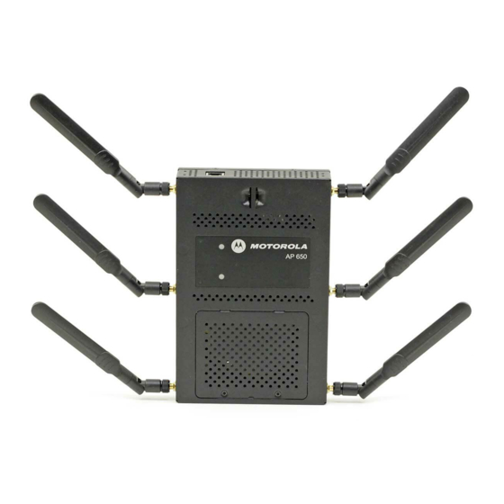
Introduction Introduction The AP-650 Thin Access Point, a component of the Motorola Wireless Switch System, links wireless 802.11a/b/g/n devices to the switch, enabling growth of your wireless network with a cost-effective alternative to standard access points. The AP-650 Thin Access Point provides two placement options: wall and ceiling. -
Page 7: Site Preparation
AP-650 Series Thin Access Point: Installation Guide 1.3 Site Preparation Consult your site survey and network analysis reports to determine specific equipment • placement, power drops, and so on. Assign installation responsibility to the appropriate personnel. • Identify and document where all installed components are located. -
Page 8: Features
Introduction 1.5 Features One RJ-45 connector • LED indicators • Safety wire tie point • Slots for wall mounting • Clips for mounting on a suspended ceiling T-bar • Lock port for Kensington® style Security Lock • The AP-650 Thin Access Point has one RJ-45 connector supporting an 10/100/1000 Ethernet port and requires 802.3af-compliant power from an external source. -
Page 9: Hardware Installation
AP-650 Series Thin Access Point: Installation Guide Hardware Installation 2.1 Installation Instructions The AP-650 Thin Access Point mounts either on a wall with wide-shoulder screws or on a suspended ceiling T-bar. This unit is not designed for mounting on a desk. -
Page 10: Precautions
• Install the access point at an ideal height of 10 feet from the ground. • Orient the access point antennas vertically for best reception. To maximize the access point’s radio coverage area, Motorola recommends conducting a site survey to define and document radio interference obstacles before installing the access point. -
Page 11: Wall Mount Hardware
AP-650 Series Thin Access Point: Installation Guide 2.4.1 Wall Mount Hardware Two wide-shoulder Phillips pan head self-tapping screws • Two wall anchors • Security cable (optional) • In the event that the original mounting screws are lost, the following NOTE screws can be used instead: (ANSI Standard) #6-18 X 0.875in. -
Page 12: Wall Mount Procedure
Hardware Installation 2.4.2 Wall Mount Procedure Integrated Antenna Wall Mount 1. Orient the case on the wall by its width or length. Correct Orientation Incorrect Orientation To ensure proper operation of the AP-650 Thin Access Point ensure CAUTION that the thin access point is mounted in the correct orientation as shown above. - Page 13 AP-650 Series Thin Access Point: Installation Guide 3. At each point, drill a hole in the wall, insert an anchor, screw into the anchor the wall mounting screw and stop when there is 1mm between the screw head and the wall.
-
Page 14: Integrated Antenna Model Suspended Ceiling T-Bar Mount Instructions
Hardware Installation 2.5 Integrated Antenna Model Suspended Ceiling T-Bar Mount Instructions Ceiling mount requires holding the AP-650 Thin Access Point up against a T-bar of a suspended ceiling grid and twisting the case onto the T-bar. 2.5.1 Suspended Ceiling Mount Procedure 1. -
Page 15: External Antenna Model Wall Mount Instructions
AP-650 Series Thin Access Point: Installation Guide 2.6 External Antenna Model Wall Mount Instructions Wall mounting requires hanging the AP-650 Thin Access Point along its width or length using the pair of slots on the bottom of the unit. The AP-650 can be mounted onto any plaster, wood, or cement wall surface using the provided wall anchors when necessary. -
Page 16: Wall Mount Procedure
Hardware Installation 2.6.2 Wall Mount Procedure 1. Orient the case on the wall by its width or length. 2. Using the arrows on one edge of the case as guides, move the edge to the midline of the mounting area and mark points on the midline for the screws. 3. -
Page 17: External Antenna Model Suspended Ceiling Tile (Plenum) Mount Instructions
The case has a safety wire tie point for a standard safety wire. Motorola does not recommend mounting the AP-650 Thin Access CAUTION Point directly to any suspended ceiling tile with a thickness less than 12.7mm (0.5in.) or a suspended ceiling tile with an unsupported span... -
Page 18: Ceiling Mount Procedure
Hardware Installation 2.7.2 Ceiling Mount Procedure Light Pipe Ceiling Tile Badge 1. If possible, remove the ceiling tile from its frame and place it, finished side down, on a work surface. 2. If required, install a safety wire, between 1.5mm (.06in.) and 2.5mm (.10in.) in diameter, in the ceiling space. -
Page 19: Ap-650 External Antenna Model Antenna Options
AP-650 Series Thin Access Point: Installation Guide 2.8 AP-650 External Antenna Model Antenna Options Motorola supports two antenna suites for AP-650 External Antenna models. One antenna suite supporting the 2.4 GHz band and another antenna suite supporting the 5 GHz band. Select an antenna model best suited to the intended operational environment of your access point. -
Page 20: Led Indicators
Hardware Installation 2.9 LED Indicators Both the Integrated Antenna model and the External Antenna model have LED activity indicators on the front of the case for use with wall mount. With the External Antenna model unit mounted above a ceiling, LEDs are at the center of an oval badge on the ceiling; a light pipe enables viewing the back LEDs through the ceiling tile. -
Page 21: Specifications
AP-650 Series Thin Access Point: Installation Guide Specifications 3.1 AP-650 External Antenna Model Electrical Characteristics An AP-650 External Antenna model Thin Access Point has the following electrical characteristics: Operating Current & 180ma- 270ma @ 48VDC Voltage 3.2 AP-650 External Antenna Model Physical Characteristics... -
Page 22: Ap-650 Integrated Antenna Model Electrical Characteristics
Specifications 3.3 AP-650 Integrated Antenna Model Electrical Characteristics An AP-650 Integrated model Thin Access Point has the following electrical characteristics: Operating Current & 180ma- 270ma @ 48VDC Voltage 3.4 AP-650 Integrated Antenna Model Physical Characteristics An AP-650 Integrated Antenna model Thin Access Point has the following physical characteristics: Dimensions 9.50 in. -
Page 23: Radio Characteristics
AP-650 Series Thin Access Point: Installation Guide 3.5 Radio Characteristics The AP-650 model Thin Access Points have the following radio characteristics: Operating Channels All channels from 4920 MHz to 5825 MHz except channel 52 -64 Channels 1-13 (2412-2472 MHz) Channel 14 (2484 MHz) Japan only Actual operating frequencies depend on regulatory approval for the country of use. -
Page 24: Regulatory Information
This devices is approved under the Symbol Technologies brand; Symbol Technologies, Inc., is the Enterprise Mobility business of Motorola, Inc (“Motorola”). All Motorola devices are designed to be compliant with rules and regulations in locations they are sold and will be labeled as required. Any changes or modifications to Motorola equipment, not expressly approved by Motorola, could void the user's authority to operate the equipment. -
Page 25: Country Selection - Note For Ap & Wireless Switch
AP-650 Series Thin Access Point: Installation Guide 4.2.1 Country Selection – Note for AP & Wireless Switch Select only the country in which you are using the device. Any other selection will make the operation of this device illegal. The US version of the Access Point will only have US listed in the country selection table. -
Page 26: Safety In Hospitals
Only operate the device in accordance with the instructions supplied. 4.5 International The device complies with internationally recognized standards covering human exposure to electromagnetic fields from radio devices. For information on “International” human exposure to eletromagnic fields refer to the Motorola/Symbol Declaration of Conformity (DoC) at http:// www2.symbol.com/doc/. -
Page 27: Us And Canada
AP-650 Series Thin Access Point: Installation Guide 4.6 EU Remote and Standalone Antenna Configurations To comply with EU RF exposure requirements, antennas that are mounted externally at remote locations or operating near users at stand-alone desktop of similar configurations must operate with a minimum separation distance of 20 cm from all persons. -
Page 28: Radio Frequency Interference Requirements - Canada
Regulatory Information • Consult the dealer or an experienced radio/TV technician for help Radio Transmitters (Part 15) This device complies with Part 15 of the FCC Rules. Operation is subject to the following two conditions: (1) this device may not cause harmful interference, and (2) this device must accept any interference received, including interference that may cause undesired operation. -
Page 29: Ce Marking And European Economic Area (Eea)
• Italy requires a user license for outside usage. 4.12 Statement of Compliance Motorola/Symbol hereby, declares that this device is in compliance with the essential requirements and other relevant provisions of Directive 1999/5/EC. A Declaration of Conformity may be obtained from http://www2.symbol.com/doc/. -
Page 30: Waste Electrical And Electronic Equipment (Weee)
Regulatory Information 4.13 Waste Electrical and Electronic Equipment (WEEE) English: For EU Customers: All products at the end of their life must be returned to Symbol for recycling. For information on how to return product, please go to: http://www.symbol.com/environmental_compliance. Dansk: Til kunder i EU: Alle produkter skal returneres til Symbol til recirkulering, når de er udtjent. -
Page 31: Turkish Weee Statement Of Compliance
AP-650 Series Thin Access Point: Installation Guide Nederlands: Voor klanten in de EU: alle producten dienen aan het einde van hun levensduur naar Symbol te worden teruggezonden voor recycling. Raadpleeg http://www.symbol.com/ environmental_compliance voor meer informatie over het terugzenden van producten. -
Page 32: Korea Warning Statement For Class B Ite
Regulatory Information 4.16 Korea Warning Statement for Class B ITE 기 종 별 사 용 자 안 내 문 B 급 기기 이 기기는 가정용 (B 급 ) 으로 전자파적합등록을 ( 가정용 방송통신기기 ) 한 기기로서 주로 가정에서 사용하는 것을 목적 으로... -
Page 33: Mexico
AP-650 Series Thin Access Point: Installation Guide 4.17.4 Mexico Restrict Frequency Range to: 2.450 – 2.4835 GHz. 4.17.5 Taiwan NOTICE! According to: Administrative Regulations on Low Power Radio Waves Radiated Devices Article 12 Without permission granted by the DGT, any company, enterprise, or user is not allowed to change frequency, enhance transmitting power or alter original characteristic as well as performance to an approved low power radio-frequency devices. -
Page 34: Korea
Regulatory Information Wireless device operate in the frequency band of 5.25-5.35 GHz, limited for Indoor use only. 在 5.25-5.35 赫頻帶內操作之無線資訊傳輸設備,限於室內使用。 4.17.6 Korea For a radio equipment using 2400~2483.5MHz or 5725~5825MHz, the following two expression should be displayed: 1. “This radio equipment can be interfered during operation.” 당해... -
Page 35: Motorola's Enterprise Mobility Support Center
• Model number or product name • Software type and version number Motorola responds to calls by email or telephone within the time limits set forth in support agreements. If you purchased your Enterprise Mobility business product from a Motorola business partner, contact that business partner for support. -
Page 36: Ap-650 Series Rohs Compliance
(Hg) (Cd) (Parts) (PBB) (PBDE) (Metal Parts) (Circuit Modules) (Cables and Cable Assemblies) (Plastic and Polymeric Parts) (Optics and Optical Components) (Batteries) SJ/T11363-2006 SJ/T11363-2006 This table was created to comply with China RoHS requirements for Motorola’s AP-650 model access points. - Page 37 AP-650 Series Thin Access Point: Installation Guide...
- Page 38 MOTOROLA INC. 1303 E. ALGONQUIN ROAD SCHAUMBURG, IL 60196 http://www.motorola.com 72E-131207-01 Revision D September 2010...
Need help?
Do you have a question about the AP-650 Series and is the answer not in the manual?
Questions and answers