Table of Contents
Advertisement
Advertisement
Table of Contents

Subscribe to Our Youtube Channel
Related Manuals for Motorola AP6532 Series


Summary of Contents for Motorola AP6532 Series
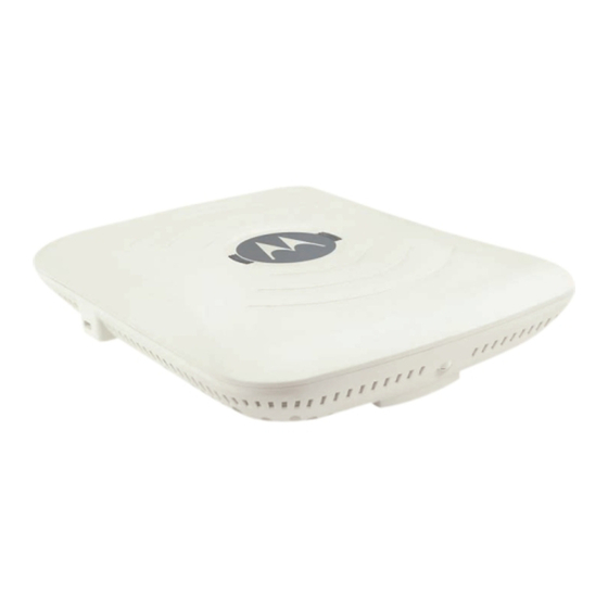
- Page 1 AP6532 Series Access Point Installation Guide...
- Page 2 MOTOROLA and the Stylized M Logo are registered in the US Patent & Trademark Office. Sym- bol is a registered trademark of Symbol Technologies, Inc. All other product or service names are the property of their respective owners. © Motorola Solutions 2011. All rights reserved.
-
Page 3: Table Of Contents
Table of Contents 1 Introduction ..................1 1.1 Document Conventions ..................1 1.2 Warnings ........................ 1 1.3 Site Preparation...................... 2 1.4 AP6532 Package Contents ..................2 1.4.1 External Antenna Model Package Contents ..........2 1.4.2 Integrated Antenna Model Package Contents..........2 1.5 Features........................ - Page 4 3 Defining a Basic Configuration ............16 3.1 Using the Initial Setup Wizard ................16 4 Specifications..................37 4.1 AP6532 External Antenna Model Electrical Characteristics........ 37 4.2 AP6532 External Antenna Model Physical Characteristics ......... 37 4.3 AP6532 Integrated Antenna Model Electrical Characteristics ......38 4.4 AP6532 Integrated Antenna Model Physical Characteristics......
- Page 5 5.17.3 Chile ......................48 5.17.4 China......................49 5.17.5 Mexico..................... 49 5.17.6 South Korea..................... 49 5.17.7 Taiwan ..................... 50 6 Motorola Solutions Enterprise Mobility Support Center ... 51 6.1 Customer Support Web Sites................51 6.2 Manuals........................ 51 7 AP6532 Series ROHS Compliance ..........52...
-
Page 6: Introduction
Introduction Introduction The AP6532 Access Point, a component of the Motorola Solutions Wireless Controller System, links wireless 802.11a/b/g/n devices to the controller, enabling growth of your wireless network with a costeffective alternative to standard Access Points. The AP6532 Access Point provides two placement options: wall and ceiling. -
Page 7: Site Preparation
AP6532 Series Access Point: Installation Guide • Verify there is adequate ventilation around the device, and that ambient temperatures meet equipment operation specifications. 1.3 Site Preparation • Consult your site survey and network analysis reports to determine specific equipment placement, power drops, and so on. -
Page 8: Features
Introduction 1.5 Features • One RJ-45 connector • LED indicators • Safety wire tie point • Slots for wall mounting • Clips for mounting on a suspended ceiling T-bar • Lock port for Kensington® style Security Lock The AP6532 Access Point has one RJ-45 connector supporting an 10/100/1000 Ethernet port and requires 802.3af-compliant power from an external source. -
Page 9: Hardware Installation
AP6532 Series Access Point: Installation Guide Hardware Installation 2.1 Installation Instructions The AP6532 Access Point mounts either on a wall (with wide-shoulder screws) or on a suspended ceiling T-bar. This unit is not designed for mounting on a desk. To prepare for the installation, perform the following: 1. -
Page 10: Precautions
Before installing an AP6532 model Access Point, verify the following: • Motorola Solutions recommends you do not to install the AP6532 in wet or dusty areas. • Verify the environment has a continuous temperature range between 0° C to 50° C. - Page 11 AP6532 Series Access Point: Installation Guide • Two wall anchors • Security cable (optional) NOTE In the event that the original mounting screws are lost, the following screws can be used instead: (ANSI Standard) #6-18 X 0.875in. Type A or AB Self-Tapping Screw, or (ANSI Standard Metric) M3.5 X 0.6 X 20mm...
-
Page 12: Wall Mount Procedure
Hardware Installation 2.4.2 Wall Mount Procedure Integrated Antenna Wall Mount 1. Orient the case on the wall by its width or length. Incorrect Orientation Correct Orientation CAUTION To ensure proper operation of the AP6532 Access Point, ensure it is mounted in the correct orientation as shown above. - Page 13 AP6532 Series Access Point: Installation Guide 2. Using the arrows on one edge of the case as guides, move the edge to the midline of the mounting area and mark points on the midline for the screws. 3. At each point, drill a hole in the wall, insert an anchor, screw into the anchor the wall mounting screw and stop when there is 1mm between the screw head and the wall.
-
Page 14: Integrated Antenna Model Suspended Ceiling T-Bar Mount Instructions
Hardware Installation 2.5 Integrated Antenna Model Suspended Ceiling T-Bar Mount Instructions Ceiling mount requires holding the AP6532 Access Point up against a T-bar of a suspended ceiling grid and twisting the case onto the T-bar. 2.5.1 Suspended Ceiling Mount Procedure 1. -
Page 15: External Antenna Model Wall Mount Instructions
AP6532 Series Access Point: Installation Guide 2.6 External Antenna Model Wall Mount Instructions Wall mounting requires hanging the AP6532 Access Point along its width or length using the pair of slots on the bottom of the unit. The AP6532 can be mounted onto any plaster, wood, or cement wall surface using the provided wall anchors. -
Page 16: Wall Mount Procedure
Hardware Installation 2.6.2 Wall Mount Procedure 1. Orient the case on the wall by its width or length. 2. Using the arrows on one edge of the case as guides, move the edge to the midline of the mounting area and mark points on the midline for the screws. 3. -
Page 17: External Antenna Model Suspended Ceiling Tile (Plenum) Mount Instructions
CAUTION Motorola Solutions does not recommend mounting the AP6532 Access Point directly to any suspended ceiling tile with a thickness less than 12.7mm (0.5in.) or a suspended ceiling tile with an unsupported span greater than 660mm (26in.). -
Page 18: Ceiling Mount Procedure
Hardware Installation 2.7.2 Ceiling Mount Procedure Light Pipe Ceiling Tile Badge 1. If possible, remove the ceiling tile from its frame and place it, finished side down, on a work surface. 2. If required, install a safety wire, between 1.5mm (.06in.) and 2.5mm (.10in.) in diameter, in the ceiling space. -
Page 19: Ap6532 External Antenna Model Antenna Options
AP6532 Series Access Point: Installation Guide 2.8 AP6532 External Antenna Model Antenna Options Motorola Solutions supports two antenna suites for AP6532 External Antenna models. One antenna suite supporting the 2.4 GHz band and another antenna suite supporting the 5 GHz band. Select an antenna model best suited to the intended operational environment of your Access Point. -
Page 20: Led Indicators
Hardware Installation 2.9 LED Indicators Both Integrated Antenna and External Antenna models have LED activity indicators on the front of the case. With the External Antenna models mounted above a ceiling, LEDs are at the center of an oval badge on the ceiling; a light pipe enables viewing the back LEDs through the ceiling tile. The LEDs provide a status display indicating error conditions, transmission, and network activity for the 5 GHz 802.11a/n (amber) radio or the 2.4 GHz 802.11b/g/n (green) radio.. -
Page 21: Defining A Basic Configuration
AP6532 Series Access Point: Installation Guide Defining a Basic Configuration An AP6532 Series access point can utilize an initial setup wizard to streamline the process of initially accessing the wireless network. The wizard defines the access point’s operational mode, deployment location, basic security, network and WLAN settings. - Page 22 Defining a Basic Configuration 3. Enter the default username admin in the Username field. 4. Enter the default password motorola in the Password field. 5. Click the Login button to load the management interface. NOTE When logging in for the first time, you’re prompted to change the password to enhance device security in subsequent logins.
- Page 23 AP6532 Series Access Point: Installation Guide 6. If this is the first time the management interface has been accessed, a dialogue displays to start the wizard. Select Start Wizard to run the initial setup wizard.
- Page 24 Defining a Basic Configuration The first page of the Initial AP Setup Wizard displays the Navigation Panel and Introduction for the configuration activities comprising the access point's initial setup...
- Page 25 AP6532 Series Access Point: Installation Guide A green checkmark to the left of an item in the Navigation Panel defines the listed task as having its minimum required configuration parameters set correctly. A red X defines the task as still requiring at least one parameter be defined correctly.
- Page 26 Defining a Basic Configuration 9. Select an Access Point Type from the following options: • Virtual Controller AP - When more than one access point is deployed, a single access point can function as a Virtual Controller AP. Up to 24 access points can be connected to, and managed by, a single Virtual Controller AP of the same AP6532 model.
- Page 27 AP6532 Series Access Point: Installation Guide NOTE If designating the access point as a Standalone AP, Motorola Solutions recommends the access point’s UI be used exclusively to define its device configuration, and not the CLI. The CLI provides the ability to define more than one profile and the UI does not.
- Page 28 Defining a Basic Configuration 11. Select an Access Point Mode from the available options. • Router Mode - In Router Mode, the access point routes traffic between the local network (LAN) and the Internet or external network (WAN). Router mode is recommended in a deployment supported by just a single access point.
- Page 29 AP6532 Series Access Point: Installation Guide...
- Page 30 Defining a Basic Configuration 13. Set the following DHCP and Static IP Address/Subnet information for the LAN interface: • Use DHCP - Select the checkbox to enable an automatic network address configuration using the access point’s DHCP server. An AP6532 access point does not have an onboard DHCP server and an external DHCP server must be utilized.
- Page 31 AP6532 Series Access Point: Installation Guide 15. Set the following DHCP and Static IP Address/Subnet information for the WAN interface: • Use DHCP - Select the checkbox to enable an automatic network address configuration using the access point’s DHCP server.
- Page 32 Defining a Basic Configuration 16. Select Next. The Initial AP Setup Wizard displays the Radio Configuration screen to define support for the 2.4GHz radio band, 5GHz radio band or to set the radio's functionality as a dedicated sensor. An AP6532 supports a single dual-band radio. NOTE The ADSP Sensor Support field displays at the bottom of the screen only if a radio has been dedicated as a sensor.
- Page 33 AP6532 Series Access Point: Installation Guide 17. Set the following parameters for the radio: • Configure as a Date Radio - Select this option to dedicate this radio for WLAN client support in either the selected 2.4 or 5GHz radio band.
- Page 34 Defining a Basic Configuration • Radio Frequency Band - Select either the 2.4GHz or 5.0GHz radio band to use with the radio when selected as a Data Radio. The selected band is used for WLAN client support. Considers selecting one radio for 2.4GHz and another for 5GHz support (if using a dual or three radio model) when supporting clients in both the 802.11bg and 802.11n bands.
- Page 35 AP6532 Series Access Point: Installation Guide 19. Set the following parameters for each of the two WLAN configurations available as part of this Initial AP Setup Wizard: • SSID - Enter or modify the Services Set Identification (SSID) associated with the WLAN.
- Page 36 Defining a Basic Configuration granted to the network. If using this option, define whether a local or external RADIUS authentication resource is used. • PSK Authentication and WPA2 Encryption - Select the option to implement a pre- shared key that must be correctly shared between the access point and requesting clients using this WLAN.
- Page 37 AP6532 Series Access Point: Installation Guide 21. Refer to the Username, Password, Description and Actions columns to review credentials of existing RADIUS Server user accounts. Add new accounts or edit the properties of existing accounts as updates are required. 22. Refer to the Add On-Board RADIUS Server Users field to set the following parameters for a user account: •...
- Page 38 Defining a Basic Configuration • Confirm Password - Re-enter (or modify) the password as a means of confirming the password. This is a required parameter. • Description - Optionally provide a description of the user account as means of further differentiating it from others.
- Page 39 • Location - Define the location of the access point. The Location parameter acts as a reminder of where the AP can be located within the Motorola Solutions managed wireless network. • Contact - Specify the contact information for the administrator. The credentials provided should accurately reflect the individual responding to service queries.
- Page 40 Defining a Basic Configuration that can be transmitted. This is a required parameter. • Time Zone - Set the time zone where the access point is deployed. This is a required parameter. The setting should be complimentary with the selected deployment country. 26.
- Page 41 AP6532 Series Access Point: Installation Guide 31. If the configuration displays as intended, select the Save/Commit button to implement these settings to the access point’s configuration. If additional changes are warranted based on the summary, either select the target page from the Navigational Panel, or use the Back...
-
Page 42: Specifications
Specifications Specifications 4.1 AP6532 External Antenna Model Electrical Characteristics An AP6532 External Antenna model Access Point has the following electrical characteristics: Operating Current & 180ma- 270ma @ 48VDC using Power over Ethernet Voltage 4.2 AP6532 External Antenna Model Physical Characteristics An AP6532 External Antenna model Access Point has the following physical characteristics: Dimensions 8.50 in. -
Page 43: Ap6532 Integrated Antenna Model Electrical Characteristics
AP6532 Series Access Point: Installation Guide 4.3 AP6532 Integrated Antenna Model Electrical Characteristics An AP6532 Integrated model Access Point has the following electrical characteristics: Operating Current & 180ma- 270ma @ 48VDC using Power over Ethernet Voltage 4.4 AP6532 Integrated Antenna Model Physical Characteristics... -
Page 44: Radio Characteristics
Specifications 4.5 Radio Characteristics The AP6532 model Access Points have the following radio characteristics: Operating Channels All channels from 4920 MHz to 5825 MHz except channel 52 -64 Channels 1-13 (2412-2472 MHz) Channel 14 (2484 MHz) Japan only Actual operating frequencies depend on regulatory approval for the country of use. -
Page 45: Regulatory Information
Motorola Solutions, Inc. (collectively "Motorola"). This guide applies to Model Number AP-0650 All Motorola/Symbol devices are designed to be compliant with rules and regulations in locations they are sold and will be labeled as required. Local language translations are available at the following website: http://supportcentral.motorola.com/... -
Page 46: Country Selection
Regulatory Information Operation of the device without regulatory approval is illegal. 5.2.1 Country Selection Select only the country in which you are using the device. Any other selection will make the operation of this device illegal. 5.2.2 Frequency of Operation – FCC and IC 5 GHz Only The use in the UNII (Unlicensed National Information Infrastructure) band 1 (5150-5250 MHz) is restricted to Indoor Use Only;... -
Page 47: Safety In Hospitals
Only operate the device in accordance with the instructions supplied. 5.5 International The device complies with internationally recognized standards covering human exposure to electromagnetic fields from radio devices. For information on "International" human exposure to electromagnic fields refer to the Motorola/Symbol Declaration of Conformity (DoC) at http://www.motorola.com/doc... -
Page 48: Europe
Regulatory Information 5.6 Europe Remote and Standalone Antenna Configurations To comply with EU RF exposure requirements, antennas that are mounted externally at remote locations or operating near users at stand-alone desktop of similar configurations must operate with a minimum separation distance of 20 cm from all persons. 5.7 US and Canada Co-located statement To comply with FCC RF exposure compliance requirement, the antenna used for this transmitter must... -
Page 49: Radio Frequency Interference Requirements-Fcc
AP6532 Series Access Point: Installation Guide 5.9 Radio Frequency Interference Requirements—FCC Note: This equipment has been tested and found to comply with the limits for a Class B digital device, pursuant to Part 15 of the FCC rules. These limits are designed to provide reasonable protection against harmful interference in a residential installation. -
Page 50: Ce Marking And European Economic Area (Eea)
• Italy requires a user license for outside usage. 5.12 Statement of Compliance Motorola/Symbol hereby, declares that this device is in compliance with the essential requirements and other relevant provisions of Directive 1999/5/EC. A Declaration of Conformity may be obtained... - Page 51 AP6532 Series Access Point: Installation Guide 5.13 Waste Electrical and Electronic Equipment (WEEE) English: For EU Customers: All products at the end of their life must be returned to Symbol for recycling. For information on how to return product, please go to: http://www.symbol.com/environmental_compliance.
- Page 52 Regulatory Information Nederlands: Voor klanten in de EU: alle producten dienen aan het einde van hun levensduur naar Symbol te worden teruggezonden voor recycling. Raadpleeg http://www.symbol.com/ environmental_compliance voor meer informatie over het terugzenden van producten. Português: Para clientes da UE: todos os produtos no fim de vida devem ser devolvidos à Symbol para reciclagem.
- Page 53 AP6532 Series Access Point: Installation Guide 5.16 Korea Warning Statement for Class B ITE 기 종 별 사 용 자 안 내 문 B 급 기기 이 기기는 가정용 (B 급 ) 으로 전자파적합등록을 ( 가정용 방송통신기기 ) 한 기기로서 주로 가정에서 사용하는 것을 목적...
- Page 54 Regulatory Information 5.17.4 China Quality Certificate in Chinese when the factory has ISO 9001 certification. 5.17.5 Mexico Restrict Frequency Range to: 2.450 – 2.4835 GHz. 5.17.6 South Korea For a radio equipment using 2400~2483.5MHz or 5725~5825MHz, the following two expression should be displayed:”...
- Page 55 AP6532 Series Access Point: Installation Guide 5.17.7 Taiwan 臺灣 低功率電波輻射性電機管理辦法 第十二條 經型式認證合格之低功率射頻電機,非經許可,公司、商號或使用者均不得擅自 變更頻率、加大功率或變更原設計之特性及功能。 第十四條 低功率射頻電機之使用不得影響飛航安全及干擾合法通信;經發現有干擾現象 時,應立即停用,且改善至無干擾時方得繼續使用。 前項合法通信,指依電信規定作業之無線電通信。 低功率射頻電機須忍受合法通信或工業、科學及醫療用電波輻射性電機設備之干 擾。 在 5.25-5.35 赫頻帶內操作之無線資訊傳輸設備,限於室內使用。...
- Page 56 • Model number or product name • Software type and version number Motorola Solutions responds to calls by email or telephone within the time limits set forth in support agreements. If you purchased your Enterprise Mobility business product from a Motorola business partner, contact that business partner for support.
- Page 57 (Plastic and Polymeric Parts) 光学和光学组件 (Optics and Optical Components) 电池 (Batteries) O: 表示该有毒有害物质在该部件所有均质材料中的含量均在 SJ/T11363-2006 标准规定的 限量要求以下。 X: 表示该有毒有害物质至少在该部件的某一均质材料中的含量超出 SJ/T11363-2006 标准 规定的限量要求。 对销售之日的所售产品,本表表示,公司供应链的电子信息产品可能包含这些物质。注 意:在所售产品中可能会也可能不会含有所有所列的部件。 This table was created to comply with China RoHS requirements for Motorola Solutions AP6532 model Access Points.
- Page 58 MOTOROLA SOLUTIONS 1303 E. ALGONQUIN ROAD SCHAUMBURG, IL 60196 http://www.motorolasolutions.com 72E-149368-01 Revision B October 2011...
Need help?
Do you have a question about the AP6532 Series and is the answer not in the manual?
Questions and answers