Motorola AP-6511 Installation Manual
Hide thumbs
Also See for AP-6511:
- Reference manual (434 pages) ,
- Reference manual (954 pages) ,
- Installation manual (46 pages)
Table of Contents
Advertisement
Quick Links
Advertisement
Table of Contents

Related Manuals for Motorola AP-6511


Summary of Contents for Motorola AP-6511
- Page 1 AP-6511 Access Point INSTALLATION GUIDE...
- Page 2 AP-6511 Access Point MOTOROLA SOLUTIONS and the Stylized M Logo are registered in the US Patent & Trademark Office. © Motorola Solutions, Inc. 2013. All rights reserved.
-
Page 3: Table Of Contents
1.4 AP-6511 Package Contents........ - Page 4 5.17 Other Countries..........38 6.0 Motorola Solutions Support Center ....... . . 41...
-
Page 5: Introduction
The AP-6511 Access Point ships with a single dual-band radio supporting the 802.11a/b/g/n radio bands. The AP-6511 receives all power and transfers data through the same CAT-5 or better Ethernet cable. There is no additional power supply required. An 802.3af PoE Ethernet switch or mid span power injector is required. -
Page 6: Warnings
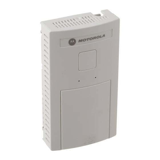
• Optional three port Ethernet expansion module (sold separately) • 2 LED indicators The pass through (keystone) cable provides an option to add a second Ethernet port before installing the AP-6511. The AP-6511 has one RJ-45 connector supporting an 10/100 Ethernet port and requires 802.3af compliant power from an external source. - Page 7 The runtime firmware on the Access Point can be updated via the Ethernet interface. The front of the AP-6511 has an access cover that can be removed to expose an additional connector. A three port RJ-45 Ethernet expansion module connects to the hidden header and snaps onto the AP-6511 in place of the access cover.
-
Page 8: Hardware Installation
AP-6511 Access Point Hardware Installation 2.1 Installation Instructions An AP-6511 Access Point mounts either on a wall, under a table or over a Telco Box. The AP-6511 is not plenum rated. The provided metal mounting plate is fastened to an existing standard NOTE Telco in-wall box. -
Page 9: Precautions
A Motorola Solutions Power Injector (AP-PSBIAS-2P2-AFR) is recommended as the 802.3af compatible power supply for the AP-6511. The Power Injector is capable of providing 12.95 Watts up to 100 meters. The Power Injector is separately ordered and not shipped with the AP-6511. A separate Power Injector is required for each Access Point comprising the network. -
Page 10: Wall Mount Installation
2.5 Wall Mount Installation Ceiling mount requires holding the AP-6511 Access Point up against a T-bar of a suspended ceiling grid and twisting the case onto the T-bar. Motorola Solutions recommends the following customer supplied... - Page 11 Bend the cable into a “U” shape so the mini pin connector and the RJ-45 keystone cable are in close proximity to one another. b. Install the mini pin connector into the pin socket on the back of the AP-6511. The connector is keyed and can only be installed one way. Ensure the mini pin connector is connected securely.
- Page 12 AP-6511 Access Point 4. Snap the AP-6511 on to the mounted wall plate. Use the locking screw to secure the unit. This connection does not require the use of tools or fastening hardware. Once installed, connections are hidden from forward view, with only the physical infrastructure cables (Ethernet and power) extending from the AP-6511.
-
Page 13: Telco Box Installation
2. Snap out keystone connectors from existing plate. 3. Gently pull some cable out of the wall so it can be used with the AP-6511 Access Point. 4. Attach the metal mounting plate (shipped with the AP-6511) to an existing standard Telco in-wall box. - Page 14 AP-6511 Access Point The screws used to mount the bracket to the Telco Box are customer provided. You can use the same screws that covered the existing wall plate if necessary. Mount the bracket to the wall so the Telco Box is ready available behind the mounting plate.
- Page 15 Bend the cable into a “U” shape so the mini pin connector and the RJ-45 keystone cable are in close proximity to one another. b. Install the mini pin connector into the pin socket on the back of the AP-6511. The connector is keyed and can only be installed one way. Ensure the mini pin connector is connected securely.
- Page 16 AP-6511 Access Point 9. Snap the AP-6511 on to the mounted wall plate and secure the AP-6511 using the mounting plate lock screw. This connection does not require the use of tools or fastening hardware. 10. Cable the Access Point using a Power Injector solution (AP-PSBIAS-2P2-AFR) as described in the following: e.
-
Page 17: Ap-6511 Antennas
802.11bgn (2.4 GHz) and 802.11an (5.0 GHz) bands. No customer assembly or antenna orientation is required. The AP-6511 radio can transmit on one or two antennas depending on the operating modes. The radio can receive on one or two antennas as well. The data rates supported are different in each case. -
Page 18: Basic Access Point Configuration
AP-6511 Access Point Basic Access Point Configuration Once the Access Point is installed and powered on, complete the following steps to get the device up and running and access management functions: 1. Attach an Ethernet cable from the Access Point to a controller with an 802.3af compatible power source or use the PWRS-14000-148R power supply to supply power to the Access Point (once fully cabled). - Page 19 Installation Guide 3. Enter the default username admin in the Username field. 4. Enter the default password motorola in the Password field. 5. Click the Login button to load the management interface. When logging in for the first time, you’re prompted to change the NOTE password to enhance device security in subsequent logins.
- Page 20 AP-6511 Access Point The Initial Setup Wizard displays the same pages and content for each NOTE Access Point model supported. The only difference being the number of radios configurable by model, as an AP7131 model can support up to three radios, AP6522, AP6532, AP6562, AP8132 and AP7161 models support two radios and AP6511 and AP6521 models support a single radio.
- Page 21 Installation Guide 7. Select Save/Commit within each page to save the updates made to that page's configuration. Select Next to proceed to the next page listed in the Navigation Panel without saving your updates. While you can navigate to any page in the navigation panel, you cannot NOTE complete the Initial AP Setup Wizard until each task in the Navigation Panel has a green checkmark.
- Page 22 UI to connect to the Access Point, provision its configuration and administrate the Access Point’s configuration. If designating the Access Point as a Standalone AP, Motorola Solutions NOTE recommends the Access Point’s UI be used exclusively to define its device configuration, and not the CLI.
- Page 23 Installation Guide 13. The Typical Setup Wizard displays the Network Topology screen to define how the Access Point handles network traffic. 14. Select an Access Point Mode from the available options. • Router Mode -In Router Mode, the Access Point routes traffic between the local network (LAN) and the Internet or external network (WAN).
- Page 24 AP-6511 Access Point 15. Select Next. The Typical Setup Wizard displays the LAN Configuration screen to set the Access Point's LAN interface configuration. 16. Set the following DHCP and Static IP Address/Subnet information for the LAN interface: • Use DHCP - Select the checkbox to enable an automatic network address configuration using the Access Point’s DHCP server.
- Page 25 Installation Guide • DNS Forwarding - Select this option to allow a DNS server to translate domain names into IP addresses. If this option is not selected, a primary and secondary DNS resource must be specified. DNS forwarding is useful when a request for a domain name is made but the DNS server, responsible for converting the name into its corresponding IP address, cannot locate the matching IP address.
- Page 26 AP-6511 Access Point 19. Select Next. The Typical Setup Wizard displays the RADIUS Server Configuration screen if required. Otherwise, the Typical Setup Wizard displays the Summary and Commit screen. 20. Use the Radius Server Configuration screen to configure the users for the onboard RADIUS server. Use...
- Page 27 Installation Guide 21. Select Add User to display the dialog to enter user information to add to the RADIUS server user database. 22. Enter the following user information: • Username - Provide a user name used to authenticate the user. •...
- Page 28 AP-6511 Access Point 28. Select Next. The Typical Setup Wizard displays the Summary and Commit screen to summarize the screens (pages) and settings updated using the Typical Setup Wizard. No user intervention or additional settings are required. Its an additional means of validating the Access Point’s updated configuration before it’s deployed.
-
Page 29: Specifications
Installation Guide Specifications 4.1 Electrical Characteristics An AP-6511 model Access Point has the following electrical characteristics: Operating Current & 250mA@48VDC Voltage 4.2 Physical Characteristics An AP-6511 model Access Point has the following physical characteristics: Dimensions 2.75 width x 5 height x 1.25 deep (Inches) 6.985 width x 12.7 height x 3.175 deep (centimeters) -
Page 30: Radio Characteristics
AP-6511 Access Point 4.3 Radio Characteristics An AP-6511 model Access Points have the following radio characteristics: Operating Channels 2.4 GHz - Channels 1-13 5 GHz - Channels 36-64; channels 100 - 165 Actual operating frequencies depend on regulatory approval for the country of use. -
Page 31: Regulatory Information
This device is approved under the Motorola brand. This guide applies to Model Number AP-6511. All Motorola/Symbol devices are designed to be compliant with rules and regulations in locations they are sold and will be labeled as required. Local language translations are available at the following website: http://www.motorolasolutions.com/support... -
Page 32: Frequency Of Operation - Fcc And Ic
AP-6511 Access Point 5.2.2 Frequency of Operation – FCC and IC 5 GHz Only The use on UNII (Unlicensed National Information Infrastructure) Band 1 5150-5250 MHz is restricted to indoor use only, any other use will make the operation of this device illegal. -
Page 33: Rf Exposure Guidelines
Only operate the device in accordance with the instructions supplied. 5.5 International The device complies with internationally recognized standards covering human exposure to electromagnetic fields from radio devices. For information on “International” human exposure to eletromagnic fields refer to the Motorola Solutions Declaration of Conformity (DoC) at http://www.motorolasolutions.com/doc 5.6 EU... -
Page 34: Power Supply
AP-6511 Access Point 5.8 Power Supply This device is powered from a 802.3af compliant power source which is UL approved and certified by the appropriate agencies. 5.9 Radio Frequency Interference Requirements—FCC This equipment has been tested and found to comply with the limits for a Class B digital device, pursuant to Part 15 of the FCC rules. -
Page 35: Ce Marking And European Economic Area (Eea)
5.13 Statement of Compliance Motorola Solutions hereby, declares that this device is in compliance with the essential requirements and other relevant provisions of Directive 1999/5/EC. A Declaration of Conformity may be obtained from... -
Page 36: Waste Electrical And Electronic Equipment (Weee)
AP-6511 Access Point 5.14 Waste Electrical and Electronic Equipment (WEEE) English: For EU Customers: All products at the end of their life must be returned to Motorola Solutions for recycling. For information on how to return product, please go to: http://www.motorolasolutions.com/recycling/weee. -
Page 37: Turkish Weee Statement Of Compliance
Installation Guide Dansk: Til kunder i EU: Alle produkter skal returneres til Motorola Solutions til recirkulering, når de er udtjent. Læs oplysningerne om returnering af produkter på: http://www.motorolasolutions.com/recycling/weee. Ελληνικά: Για πελάτες στην Ε.Ε.: Όλα τα προϊόντα, στο τέλος της διάρκειας ζωής τους, πρέπει να επιστρέφονται... -
Page 38: Japan (Vcci) - Voluntary Control Council For Interference Class B Ite
Regulatory declarations for AP-6511 - BRAZIL Note: The certification mark applied to the AP-6511 is for Restrict Radiation Equipment. This equipment operates on a secondary basis and does not have the right for protection against harmful interference from other users including same equipment types. - Page 39 Installation Guide “Este equipo cumple con la Resolución No 403 de 2008, de la Subsecretaria de telecomunicaciones, relativa a radiaciones electromagnéticas.”. "This device complies with the Resolution Not 403 of 2008, of the Undersecretary of telecommunications, relating to electromagnetic radiation.” Mexico Restrict Frequency Range to: 2.450 –...
- Page 40 AP-6511 Access Point 在 5.25-5.35 赫頻帶內操作之無線資訊傳輸設備,限於室內使用。 Korea For radio equipment using 2400~2483.5MHz or 5725~5825MHz, the following expressions should be displayed: 4. “This radio equipment can be interfered with during operation.” 당해 무선설비는 운용 중 전파혼신 가능성이 있음 5. “This radio equipment cannot provide a service relevant to human life safety, as it can be crossed” through the user manual, etc.
-
Page 41: Motorola Solutions Support Center
• Model number or product name • Software type and version number Motorola Solutions responds to calls by e-mail, telephone, or fax within the time limits set forth in support agreements. If you purchased your product from a Motorola Solutions business partner, contact that business partner for support. - Page 42 AP-6511 Access Point...
- Page 43 Installation Guide...
- Page 44 Schaumburg, IL 60196-1078, U.S.A. http://www.motorolasolutions.com MOTOROLA, MOTO, MOTOROLA SOLUTIONS and the Stylized M Logo are trademarks or registered trademarks of Motorola Trademark Holdings, LLC and are used under license. All other trademarks are the property of their respective owners. © 2013 Motorola Solutions, Inc. All Rights Reserved.
Need help?
Do you have a question about the AP-6511 and is the answer not in the manual?
Questions and answers