Bticino D45 Technical Manual
Vde system video door entry system
Hide thumbs
Also See for D45:
- Manual (10 pages) ,
- Quick start manual (4 pages) ,
- Instruction manual (4 pages)
Table of Contents
Advertisement
Advertisement
Table of Contents
Troubleshooting

Related Manuals for Bticino D45


Summary of Contents for Bticino D45
- Page 1 System technical guide...
- Page 3 INDEX D45 VIDEO DOOR ENTRY SYSTEM General features and devices overview . . . . . . . . 02 Installation rules . . . . . . . . . . . . . . . . . . . . . . . 73 Configuration concept and examples .
- Page 4 . The system can satisfy different size requirements, based Main feature of the D45 system: the use of CAT5 cables on riser, building, district, or TCP/IP network, ensuring the for the whole system, ensuring easy installation, and cost most economical system project;...
- Page 5 30 V/2 A ACCESSORIES APARTMENT INTERFACE 323009 DIN Rail 141*105*33 mm 30 V/40 mA 30 V/140 mA 346858 D45/2 WIRE INTERFACE DIN Rail 72*105*33 mm 30 V/1 mA 30 V/20 mA D45/IP INTERFACE 323011 DIN Rail 90*175*60 mm 30 V/130 mA...
- Page 6 CARATTERISTICHE GENERALI SONORA - VIDEO DOOR ENTRY SYSTEM - GENERAL FEATURES Entrance panel functions overview 322010 - Digital entrance panel colour With alloy-die-casting panel with luxurious and elegant appearance . The touchtone keyboard, stable in function, for direct handset call and communication . With a blue night-light display . Features Functions such as monitoring, call, conversation, door lock release, etc .
- Page 7 322010 legenD 1 . Compensation Lamp GND/DAS: electronic lock status signal connector 2 . Confirm menu setting or other operation LOCK-/LOCK+: connect electronic lock . 3 . Number keyboard: call the handset and function setting 19 . SPK-OUT/GND/GND/SPK-OUT: connect entrance panel 4 .
- Page 8 CARATTERISTICHE GENERALI SONORA - VIDEO DOOR ENTRY SYSTEM - GENERAL FEATURES Entrance panel functions overview 322010 Digital ep call by the visitors 1 . A visitor can input the resident’s number as per Handset monitors and entrance panels: the prompt on the display and press the # key for When the entrance panel is idle, the resident can press the confirmation .
-
Page 9: Call Transfer
call transFer alarm For the Distress coDe In case that the entry panel is used as (Riser EP or secondary When the six-digit user password is entered for unlocking, EP), visitors or residents can call the Switchboard from and if the user re-enter the distress code “5” and presses the the entrance panel and ask to be put through to a certain key for confirmation, then the entry panel shall send the handset . - Page 10 CARATTERISTICHE GENERALI SONORA - VIDEO DOOR ENTRY SYSTEM - GENERAL FEATURES Entrance panel functions overview 322010 Digital ep set the Functions When used as (Backbone EP or main EP): Press the # key for about 5 seconds . Input the master Mode 3 and Mode 4: these are commonly used modes .
- Page 11 Mode 7 and Mode 8: When there are several zones in one 9 . Select 9 to complete the relevant settings of the project and we need the zone number for a call, we can password door lock release function . There are three available options: select one of them .
- Page 12 CARATTERISTICHE GENERALI SONORA - VIDEO DOOR ENTRY SYSTEM - GENERAL FEATURES Entrance panel functions overview conFigure the ep parameters It can download or update the software through the ISP The configuration parameters for the EP can be set either port, no need to open the cover . through Item 5 in the function settings under the LCD interface, or by means of the configurator .
- Page 13 322020 small ep Small colour entrance panel Independent video door phone set, which should be installed by the apartment door . Aluminium alloy panel brings luxury and a classic look; touch tone pushbuttons with stable performance; for calling and communicating directly with handsets .
- Page 14 321010 colour handset with alarm, 321030 B/W handset with alarm and 321020 B/W handset with alarm can be connected to the D45 EP through the main system riser . The main system riser can be connected to the Switchboard to perform functions such as conversation, monitor and VDE functions .
- Page 15 322050 - colour hanDsFree 7” legenD 1 . Loudspeaker 14 . Number keys and corresponding numbers 2 . SOS key 15 . Alarm zone LEDs 1 to 8 3 . Monitor key 16 . Display screen 4 . Information LED 17 .
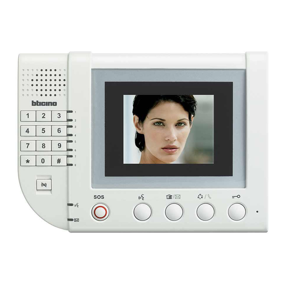
- Page 16 CARATTERISTICHE GENERALI SONORA - VIDEO DOOR ENTRY SYSTEM - GENERAL FEATURES Indoor handset functions overview 321010 - colour hanDsFree 5.6” legenD 1 . Ring control knob 14 . Answer key 15 . SOS key 2 . Brightness control knob 16 . Information LED 3 .
- Page 17 321030 - b/w 4” hanDset legenD 12 . SOS key 1 . Ring control knob 13 . Sensor anti-removal alarm connector 14 . Alarm sensors connector (see Wiring diagram 15) 2 . Brightness control knob 15 . Small EP connector 3 .
- Page 18 CARATTERISTICHE GENERALI SONORA - VIDEO DOOR ENTRY SYSTEM - GENERAL FEATURES Indoor handset functions overview 321020 - b/w hanDsFree 4” legenD: 13 . SOS key 1 . Ring control knob 2 . Brightness control knob 14 . Microphone 15 . Sensor anti-removal alarm connector 3 .
- Page 19 hanDsets user settings With the handset is standby, enter the user password+ “#”pushbutton. If the wrong password is entered, 3 short beeps will be heard. If the password is correct, the device will enter the main settings menu and an extended beep will be heard. FuncTional lisT For seTTing and channel alarMs seTup iTeM operaTion code...
-
Page 20: Receiving Calls
CARATTERISTICHE GENERALI SONORA - VIDEO DOOR ENTRY SYSTEM - GENERAL FEATURES Indoor handset functions overview Video door entry functions instructions hanDset monitoring other Devices 1 . For all pushbuttons, the operation is only performed Small EP monitoring after the pushbutton is released . When holding the Press the monitor pushbutton twice while in standby . - Page 21 timing sos alarm The longest time the handset can be in operation before SOS pushbutton on the panel picking up the receiver or answering the call is 30 s, after this The SOS alarm message will be sent to Switchboard by time the handset automatically switches to standby mode .
- Page 22 CARATTERISTICHE GENERALI SONORA - VIDEO DOOR ENTRY SYSTEM - GENERAL FEATURES Indoor handset functions overview Ring volume/ silent mode setup Setting the number of apartments per While in standby, adjust ring adjustment knob to change floor the ringing volume . When call light turns red, it means the 1 .
- Page 23 master anD slave settings Slave Master MasTer and slave seTTings MasTer MasTer and slave seTTings slave Set as the master handset Set as the slave handset Or not jump Alarm sensors connections Drawings as above, set at the back of the handset according to the marks .
- Page 24 CARATTERISTICHE GENERALI SONORA - VIDEO DOOR ENTRY SYSTEM - GENERAL FEATURES Indoor handset functions overview installation setup When the handset is in standby and all zone alarms are disabled, beeps will be heard; if the password is correct, an extended press “#”, then enter the fixed installer password 686868, and beep will be heard, and the unit will switch to installation setup press “#”...
- Page 25 insTallaTion seTTing operaTion lisT Table seTup operaTion code and nexT Meaning and inForMaTion For The operaTion reMark lighT sTaTus operaTion Set infrared sensor infrared sensor for alarm zone 5: LED 5 on, 1 long tone Message light is off. 8 alarm lights non- infrared sensor for alarm zone 5: LED 5 on, 1 long tone will indicate status of infrared return to previous menu, 1 short tone...
-
Page 26: Troubleshooting
CARATTERISTICHE GENERALI SONORA - VIDEO DOOR ENTRY SYSTEM - GENERAL FEATURES Indoor handset functions overview troubleshooting 1 . Small EP short circuit. The handset emits 3 short beeps, stops communication with the Small EP and switches to standby . 2 . Overload or short circuit check for alarm sensor . After setting the alarm zone, the handset will supply 12 ±1V DC to the sensors . -
Page 27: Installation Notes
322040 - auDio hanDset Audio handset 322040 Functions 322040 is an audio handset . It has basic functions such as VDP and door lock release . It’s small in size and has a low power consumption . outlook anD connector Introduction Unless otherwise specified, the functions described below are all in normal mode . - Page 28 CARATTERISTICHE GENERALI SONORA - VIDEO DOOR ENTRY SYSTEM - GENERAL FEATURES Indoor handset functions overview 322040 - auDio hanDset Set the installation parameters Set the handset household no . FuncTions operaTion reMarks Enter the household number setup While in the initial installation setup status press and hold down the MC pushbutton once to enter the household submenu number setup submenu.
- Page 29 Setting the number of households per floor FuncTions operaTion reMarks Enter setup submenu for number of While in the initial installation setup status, press and hold the MC pushbutton twice to enter the setup submenu for The number of households per floor cannot be households per floor the number of households per floor.
- Page 30 CARATTERISTICHE GENERALI SONORA - VIDEO DOOR ENTRY SYSTEM - GENERAL FEATURES Indoor handset functions overview 322040 - auDio master anD slave hanDset FuncTions operaTion reMarks Select the “Set master and slave While in the initial installation setup status, press and hold the MC pushbutton 8 times to enter the setup submenu Note: only one master handset per household handsets”...
- Page 31 Recovering all the default parameters FuncTions operaTion reMarks Select setup submenu of “recover all the While in the initial installation setup status, press and hold the MC pushbutton nine times to enter the setup submenu Default: disable. this means that the handset is default parameters”...
- Page 32 CARATTERISTICHE GENERALI SONORA - VIDEO DOOR ENTRY SYSTEM - GENERAL FEATURES Indoor handset functions overview timing Door lock release The longest time the handset can be in operation before When the handset and the EP are in communication, press picking up the receiver or answering the call is 30 s, after this the door lock release pushbutton to release the EP door lock .
- Page 33 Switchboard overview 323001 - switchboarD Switchboard The Switchboard is the core of the network system intelligently managed residential apartment blocks . It is based on 32 bit embedded CPU and FPGA platform technology with high resolution 7“ digital LCD . The device can manage not only the local computerised Switchboard system, but can also be linked by LAN to other computerised Switchboard for the management of larger systems .
-
Page 34: Main Features
CARATTERISTICHE GENERALI SONORA - VIDEO DOOR ENTRY SYSTEM - GENERAL FEATURES Switchboard overview 323001 - switchboarD legenD DIP switch setting instruction 20 . jTAG connector Distance 21 . Video output amplifying DIP switch 0 – 300 m colour or b/w video 22 . - Page 35 Function Features 7 . Communication record management: capable of 1 . Digital intelligent control . Navigation pushbutton, recording thousands of communication records, which with graphic icon menu for easy operation . Possibility are easy to browse; of real time caller and recipient address information 8 .
- Page 36 CARATTERISTICHE GENERALI SONORA - VIDEO DOOR ENTRY SYSTEM - GENERAL FEATURES Switchboard overview 323001 - switchboarD Message record: use the navigation key to choose this icon, press “OK” to enter the message records interface, which includes the following info: Missed call list press “” and “”to browse Answered calls answered call list press “”, “”...
- Page 37 System accessories overview 323003 - riser shunt Riser shunt The riser shunt is used to connect the riser BUS and system BUS in order to separate BUS, transfer signal and switch between video and audio channels . The device has five Rj45 connectors, which are for riser BUS input/ output, system BUS input/ output .
- Page 38 CARATTERISTICHE GENERALI SONORA - VIDEO DOOR ENTRY SYSTEM - GENERAL FEATURES System accessories overview 323003 - riser shunt For example: conFigure cF4 as 5 1 . Enter configuration status: in standby press input key S1 1 . Configuration using physical configurators and hold for 2 s .
- Page 39 323002 - Floor shunt A floor shunt should be installed between floors . Using a Floor shunt signal cable, each apartment handset is connected to the BUS through item 323002 . One 323002 can be connected to 4 handsets . The device converts the BUS video signals to transfer mode and then distributes them to the connected handsets .
- Page 40 CARATTERISTICHE GENERALI SONORA - VIDEO DOOR ENTRY SYSTEM - GENERAL FEATURES System accessories overview 323016 - villa shunt Villa shunt Villa shunt is installed in the public low voltage box in villas areas . The handset of each villa’s resident can connect all the signal lines to the bus through the Floor shunt and the Villa shunt .
- Page 41 example Typical Wiring Diagram of Villa shunt . System wiring diagram for the detached villas . Floor Shunt 323002 HANDSET 323016 323002 I U 1 I U 2 I U 3 V -G A I N S U B S Y S T E M O U T I U 4 Villa Shunt 323016...
- Page 42 CARATTERISTICHE GENERALI SONORA - VIDEO DOOR ENTRY SYSTEM - GENERAL FEATURES System accessories overview 323016 - villa shunt Power options: You can select the Floor shunt power The distance between the Villa shunt and the handset supply according to the actual power consumption and must be less than 50 meters and the villa shunt can only the distance between Villa shunt and Floor shunt .
- Page 43 System wiring diagram of town villas . Floor Shunt 323002 HANDSET HANDSET 323016 323002 323002 I U 1 I U 2 I U 3 I U 1 I U 2 I U 3 V -G A I N V -G A I N S U B S Y S T E M S U B S Y S T E M O U T...
- Page 44 CARATTERISTICHE GENERALI SONORA - VIDEO DOOR ENTRY SYSTEM - GENERAL FEATURES System accessories functions overview 323004 - entrance panels viDeo mixer Video Mixer The 323004 enables connection of up to 5 entrance panels, providing management of the calls to the riser (the first entrance panel from which the call is made has priority) .
- Page 45 323007 - 2 branches viDeo splitter 2 Branches video splitter The device has one input and two outputs . It splits the BUS signal into two channels: the video signal can only be transferred from input to output . The video Splitter has 4 gears for video compensation functions .
- Page 46 CARATTERISTICHE GENERALI SONORA - VIDEO DOOR ENTRY SYSTEM - GENERAL FEATURES System accessories functions overview 323008 - basic apartment interFace Basic apartment interface 323008 should be installed between Floor shunt and handset . When one apartment has 2 or 3 handsets, please use this device to extend interfaces .
- Page 47 323009 - apartment interFace This device is installed inside the house of the user and is Apartment interface used for expanding handsets and Small EP . One Apartment interface can connect 5 handsets and one Small EP, performing the necessary functions for calling the handsets and calling and monitoring Small EP .
- Page 48 CARATTERISTICHE GENERALI SONORA - VIDEO DOOR ENTRY SYSTEM - GENERAL FEATURES System accessories functions overview 323009 - apartment interFace Typical Wiring Diagram 1 Remarks . To power this device you can either use the auxiliary power supply or the standard power supply (We recommend using the auxiliary Power supply) .
- Page 49 Typical Wiring Diagram 2 Remarks: If powered through the unit bus system, only one indoor unit can be set as the master indoor unit . 323009 To HANDSET 2 To HANDSET 3 323015 322020 323002 To HANDSET4 System output (connect to 323002 - input) System input (connect to 323002 - output) HANDSET...
- Page 50 CARATTERISTICHE GENERALI SONORA - VIDEO DOOR ENTRY SYSTEM - GENERAL FEATURES System accessories functions overview 323015 - Door lock accessory Door lock accessory 323015 accessory is an electric door lock driver, used to control the commonly used 12 V negative locks . When the Positive locks’...
- Page 51 Example: Typical Wiring of the door lock accessory 322010 323015 L+ L– L– L+ – – Electronic lock Manual pushbutton Limit distance ≤ 20 m Limit distance ≤ 250 m Line specification RV V2 x 1.0 mm Line specification RV V2 x 1.0 mm 323010 323005 Note: the above power supply belongs to the unit system power and is commonly...
- Page 52 CARATTERISTICHE GENERALI SONORA - VIDEO DOOR ENTRY SYSTEM - GENERAL FEATURES System accessories functions overview 323013 - District generator District generator 323013 is the district hub that can be connected with 4 district riser shunts, 1 wall EP connector, 1 Switchboard connector and 1 main system power connector .
- Page 53 The video gain setting can be divided into 5 branches, 2 . Enter the configuration number (select which place): press branch1, branch 2, branch 3, branch 4, wall EP, or release S2 to count . Each pressure will increase the number by message to handset channel .
- Page 54 System accessories functions overview 323011 - D45/ip interFace D45/IP interface 323011 is an IP interface that can be connected to the D45 system and the BT 2-wire IP system . It ensures compatibility with the D45 system and BT 2-wire system .
- Page 55 3 .0 . Its operating environment needs the support of Miscrosoft NET3 .5, which means that before installing the D45/IP interface Config 3 .0, NET3 .5 must be installed . After installing the D45/IP interface Config 3 .0, it can be run . The interface is shown below: Select the “INTERFACE”...
- Page 56 (the DHCP function needs to be started), or the DHCP server can dynamically distribute an IP address for the D45/IP interface . Or you can select the Fixed IP mode, which is a manual IP configuration mode . In this mode the addresses can be configured manually: the IP address will be used to configure the IP address of item 323011, defaulted at 192 .168 .1 .100 .
- Page 57 If the first D45/IP interface 1 connects 3 Risers (Riser 1, Riser 2 and Riser 3), the second D45/IP interface 2 will connect 4 Risers (Riser 4, Riser 5, Riser 6 and Riser 7) . Each Riser should be configured as per Mode 1...
- Page 58 If the first D45/IP interface 1 connects 2 main EPs and 3 Risers (Riser 1, Riser 2 and Riser 3), then each Riser will be connected to one EP . If the second D45/IP interface 2 connects 0 main EP and Risers (Riser 4, Riser 5 and Riser 6), then Riser 4 and Riser 6 are...
- Page 59 ” key and input in the correct ones . By using the “” key, you can sort an address list for the several management centres . Sorted at the top is the D45/IP interface that takes priority to call the management centre . If busy, it will be...
- Page 60 VIDEO DOOR ENTRY SYSTEM - GENERAL FEATURES System accessories functions overview 323011 - D45/ip interFace Prepare for the configuration lines The D45/IP interface has options for downloading the configuration: online download, serial port download, and USB download . 323011 PoWER SUPPLy 323010...
- Page 61 As for the above, you can select Ethernet for the configuration . Click NEXT and as shown in the following diagram . The first time “Automatic search” can be used . Click and let the system find 323011, after which you can input the password into Open Password .
- Page 62 For the installation oF item 323011 323011 323010 other 323011 or 346890 (BT’s 2-wire system IP interface) If the main EP is close to the D45/IP interface, then an auxiliary power may not be necessary. 323010 BAckBoNE/MAIN EP 323005...
- Page 63 323019 - system expansion interFace System expansion interface 323019 is used to extend riser system . When the number of handsets of one riser exceed 400, the interface can be used to extend the quantity to 800 . It’s connected by serial connection to the riser BUS to separate riser system BUS and ensure signal transmission quality by forwarding all the signals and video gain adjustments for better video...
-
Page 64: Power Supply
VIDEO DOOR ENTRY SYSTEM - GENERAL FEATURES System accessories functions overview 323005 - power supply 323010 - auxiliary power supply In D45 system, there are two types of power supply: Power supply, Auxiliary power supply 323005 and 323010 . 323005... - Page 65 Functions oF power supply connectors Functions oF connectors only For 323005 3 4 5 + - - + + - - + • Blue • Yellow and green • Brown AC input This wire must be connected to earth ground legenD legenD 1 .
- Page 66 CARATTERISTICHE GENERALI SONORA - VIDEO DOOR ENTRY SYSTEM - GENERAL FEATURES System accessories functions overview 323005 - power supply 2 . Enter the configurator number (i .e . select one configurator): press S2 to count . Each pressure will 323010 - auxiliary power supply increase the number by one (no press= 1st one) and the When the impedance switch is ON, 323005 is set as system CFG light will flash once .
- Page 67 323018 - ep/switchboarD shunt EP/Switchboard shunt It uses a microprocessor for interface control, and can automatically switch the video channels over . There are 2 configuration methods, by resistor configurator or by pushbutton setting . Once configured it can be used as a Switchboard or main EP backbone expansion interface and can support several wiring methods .
- Page 68 CARATTERISTICHE GENERALI SONORA - VIDEO DOOR ENTRY SYSTEM - GENERAL FEATURES System accessories functions overview 323018 - ep/switchboarD shunt Introduction to the configuration procedures 1 . Resistor configurator procedure . Insert the resistor DEV: Options of main EP/Switchboard types configurator of appropriate value into the EP/ Switchboard shunt configurator to perform EP/ Switchboard Switchboard shunt configuration .
- Page 69 Each pushbutton-configuration place must be relevant to In this case connect the non-zero (1 to 9) resistor to the place at the configurator . For example, if the pushbutton the configurator and repower to clear all the values configuration place is coded at 5, then it’s relevant to configured using the pushbuttons .
- Page 70 CARATTERISTICHE GENERALI SONORA - VIDEO DOOR ENTRY SYSTEM - GENERAL FEATURES System accessories functions overview 323018 - ep/switchboarD shunt example: typical wiring oF ep/switchboarD shunt X X X X 1 1 X X X X 1 1 X X X X 0 1 X X X X 0 1 323003 323018...
- Page 71 D45 to 2 wire interface D45/BTicino 2-wire interface (346858) is a switch-over interface device made by BTicino that can be used for installing the BTicino 2 wire system or BTicino 2 wire intelligent home devices in the D45 system .
- Page 72 2 . If the unit building relevant to 346858 has 28 floors, 3 346858 can be configured in two ways: 1) simple households on each floor, then D45 system can use Mode configuration (Mode 1); 2) flexible configuration (Mode 2) 2 for the system configuration .
- Page 73 This package consists of the Tool interface and the Tool interface Configuration tool, used by technicians to download the configuration information or update programs for the target devices (EP and interface, etc .) of the D45 system . packing list Tool interface 1 piece...
- Page 74 CARATTERISTICHE GENERALI SONORA - VIDEO DOOR ENTRY SYSTEM - GENERAL FEATURES System accessories functions overview 323020 - conFiguration tool leFT relevanT connecTion as per The digiTs righT Relevant connections as per the digits 5GND Left (male connector) Right (Female connector) Wiring method 2: Only for firmware specialist to upgrade .
-
Page 75: Table Of Contents
INDEX INSTALLATION RULES Entrance panels and indoor handsets installation . 74 System cable . . . . . . . . . . . . . . . . . . . . . . . . . 77 Standard Rj45 connections . - Page 76 CARATTERISTICHE GENERALI SONORA - VIDEO DOOR ENTRY SYSTEM - GENERAL FEATURES Entrance panels and indoor handsets installation small ep/ep/main ep installation height hanDset installation height Below is the recommended installation height for the When installing audio or video internal units, it is advisable to position the devices as indicated here .
-
Page 77: Installation Method
Entrance panel installation 322010 installation methoD 125 mm 60 .5 mm Size overview Don’t install in hot or damp places Flush mounted box Flush mounted box Screw Screw Rack Rack Install the EP on the wall Install the EP on the door Note: The flush mounted box must be ordered separately. - Page 78 VIDEO DOOR ENTRY SYSTEM - INSTALLATION RULES Small entrance panel installation 322020 installation methoD 108 mm 30 mm > 1 .00 m Don’t install in hot or damp places Size overview Installation height and position Do not install in hot or Damp places Installation method 1 Installation instruction: 1 .
-
Page 79: System Cable
System cable The D45 system only works correctly if CAT5 original cables are used . Twisted pairs offer good standard and differential immunity . The CAT5 cable must have a resistance value of 180 ohm/km ( for every twisted pair) . - Page 80 VIDEO DOOR ENTRY SYSTEM - INSTALLATION RULES Standard Rj45 connections for CAT5 cable Two standards (T568A and T568B) of wires connection, both suitable, although it is recommended that they are not mixed in the same installation . Table 1 shows the two standards . Where is Pin #1? Pair 2 Pair 3...
- Page 81 Rj45 connections rJ45 wire map anD connection methoD wire Map Colour White&orange Orange White&green Blue White&blue Green White&brown Brown SIGNAL Video+ Video- Audio+ Power+ Power– Audio- Data- Data+ Wire specification: cAT cable 1 . Tools for making and testing CAT5 connections . 2 .
- Page 82 VIDEO DOOR ENTRY SYSTEM - INSTALLATION RULES Rj45 connections Step 5: Hold the Rj-45 connector Step 6: Before lock the wires inside the Step 7: after the final check, Place the between your fingers with the copper connector, check from the top of the attached Rj-45 connector into the wire connectors face up .
- Page 83 Lock type and distance limits recommenDeD rJ45 connector The actual working environment may be damp or hot, which can cause inferior Rj45 connectors to rust . We recommend that Legrand/Ortronics connectors are used (see specific catalogue) . The types of door locks below are also recommended (Shows diagram as figure 1) . No need of power for door lock during stand-b, Door lock releaseVoltage: DC12 V, Door lock releaseCurrent: ≤1 A, Time needed to release the lock (output voltage to release the lock) : ≤100 ms EP/WEP...
- Page 84 VIDEO DOOR ENTRY SYSTEM - INSTALLATION RULES Lock type and distance limits For this kind of door lock, an additional power supply must be used . The connection method is shown below . EP/WEP L-L+ Door lock release Lock 323015 Power Power supply...
- Page 85 Power supply installation rules There are two kinds of power supplies for D45 systems, the system and the auxiliary power supply . Power supply 323005 Riser shunt: 323005 323010 Where system power supply is needed: in D45 systems it is...
- Page 86 VIDEO DOOR ENTRY SYSTEM - INSTALLATION RULES Power supply installation rules legenD one 323005 is needed in the main network area one 323005is needed in the green area of the unit one 323005 is needed in the blue area connected to - 323019 UNIT 2 HANDSET HANDSET...
- Page 87 recommenDeD pws solution anD relateD conFiguration no. insTallaTion power supply conFiguraTion when power supply is sysTeM power supply conFiguraTion oF power supply & apower supply sTaTus oF soluTion (impedance switch of Power supply must be ON) when Power supply is assistant power supply (impedance switch of sysTeM Power supply must be OFF) CF12...
- Page 88 VIDEO DOOR ENTRY SYSTEM - INSTALLATION RULES Power supply installation rules connection anD setup proceDure For 323005 (Set 323005 as system power supply) Connector for 323005 Difference for each connector line power video audio daTa colour connecTion connecTion connecTion connecTion √...
- Page 89 connection anD setup proceDure For 323005 5) When there is a Switchboard in the system, 323001 will get power from system BUS power supply . The system 3) When there is no 323013 on the system BUS , the system power supply on the BUS should be connected and set as BUS power supply should be connected and set as per the per the following drawing:...
- Page 90 VIDEO DOOR ENTRY SYSTEM - INSTALLATION RULES Power supply installation rules connection anD setup proceDure For 323005 ( set PWS as additional power supply) or 323010 Connector for 323005 and 323010 1 . 323010 doesn’t have and impedance setting switch, and can only be used as auxiliary power supply . 2 .
- Page 91 Power supply check and calculation Before proceeding to the system installation, it is necessary to check the power supply of the whole system: 1 . Check that the power supplies are enough to supply 3 . Maximum distance between Floor shunt and handset the power current needed by the devices to install the Maximum distance = 50m (CAT5 Cable);...
- Page 92 VIDEO DOOR ENTRY SYSTEM - INSTALLATION RULES Power supply check and calculation table 1 *N: in this condition (EPs quantity), the riser system power 5 . When using an entrance panel video mixer in the riser supply cannot provide current to this kind of handset, an (more than one EP in the riser), the distance between additional power supply must be used .
- Page 93 Table 5: Case 1 to Case 4, the quantity of devices managed by 323005(Power supply) HANDSET How many apartments Case 5 Case 6 Case 7 Case 8 on every floor Total Qty of Total Qty of Total Qty of Total Qty of Floor limit Floor limit Floor limit...
- Page 94 VIDEO DOOR ENTRY SYSTEM - INSTALLATION RULES Power supply check and calculation *1 : 2 small EP and 1 EP can work at the same time with handsets connected to the same power supply . *2 : 1 small EP and 1 EP can work at the same time with handsets connected to the same power supply . *3 : 3 small EP and 1 EP can work at the same time with handsets connected to the same power supply .
- Page 95 Maximum system limits device Type Max. qTy reMarks Handsets in the whole system (Non-IP 4000 The backbone/main EP can call all the handsets network system) Handsets in the whole system (IP network 4000/each IP area, expandable The Backbone/main EP can call 4000 users at most while the Switchboard can call all the users. system) Handset on each riser 323003 can carry 400 handsets at most, but can expand to 800 by connecting item 323019 in series in the unit.
- Page 96 . In D45, the maximum level of cascade is 6 . If any of the following devices is passed by a video signal in the system, the cascade level should increase by 1 level .
- Page 97 INDEX CONFIGURATION RULES General configuration concept . . . . . . . . . . . . . 96 Entrance panels configuration examples . . . . . . . 99 Handsets configuration examples .
-
Page 98: System Configuration
Switchboard operators to identify the (a design/project activity) . apartments or villas in the installation . The D45 system let Teach to the physical device its proper configuration (an you use this codes to make calls within the system . The... - Page 99 No PC support is needed/useful for these activities . A PC is not needed to configure the system on the installation - it can be used during the project phase to easily identify and check if it is possible to configure the system following the flexible Using this configuration only the default apartment functions are available .
- Page 100 265 (if only 3 handsets in each apt.) system configuration Mode 2 . Total number of apt./villas for each riser: 800 (up to 5 handsets in each apt. with D45 apt. interface) system conFiguration moDes There are 3 possible system configuration modes:...
- Page 101 EP configuration examples 322010 - Digital entrance panel conFiguration possible ep conFiguration moDes Example (A): EP address is 5, each riser has 20 floors, and each floor has 4 Mode 1 Mode 2 handset: system configuration mode 1 is used . Resistor configuration √...
- Page 102 VIDEO DOOR ENTRY SYSTEM - CONFIGURATION EP configuration examples 322010 - Digital entrance panel conFiguration Example (B): EP address, each riser has 25 floors, and each floor has If configurator or keyboard configuration is selected for the 8 handsets . System configuration mode 2 is used . the main EP, the following conditions must be met: Switchboard directly connected to the main EP is no .
- Page 103 Handset configuration examples 321010 - possible hanDset conFiguration meaning oF each conFigurator socket pin proceDure posiTion Mode 1 Mode 2 Mode 1 Mode 2 Resistor configuration √ √ (only for Colour) Default for #II is 04, Keyboard configuration √ √ need not connect the configurator (#II setup using same value for all system handsets).
- Page 104 VIDEO DOOR ENTRY SYSTEM - CONFIGURATION Handset configuration examples 321010 - hanDset conFiguration Example (B): The number of handsets is 1206, each floor has 8 handsets . System configuration mode 2 is used . The handset configuration should be as follows: posiTion value reMarks It is ok not to insert configurator 0...
- Page 105 Accessory configuration examples 323003 - riser shunt conFiguration possible riser shunt conFiguration proceDure C: the Switchboard number that is the first priority for this Mode 1 Mode 2 riser . If the number of the Switchboard is more than 9 (from Resistance configuration √...
- Page 106 VIDEO DOOR ENTRY SYSTEM - CONFIGURATION Accessory configuration examples 323003 - riser shunt conFiguration Example (A): The number of riser shunts is 5, each riser has 20 floors, and each floor has 4 handsets . The Switchboard that can be called directly by this riser is no . 2 . System configuration mode 1 is used .
- Page 107 Example (B): The number of riser shunts is 5, each riser has 25 floors, and each floor has 8 handsets . The Switchboard that can be called directly by this riser is no . 2 System configuration mode 2 is used .
- Page 108 0 main EP and 3 cells (cell 4, 5, 6), cell 4 and cell 6 connect to EP range of each cell in the D45 system is 1—80 . The main 1 EP each, cell 5 connects to 2 EP .
- Page 109 323018 - ep/switchboarD shunt conFiguration 323009 leD inDications Directions for the configuration: possible conFiguration proceDure Optional configuration alternatives for 323009 . Mode 1 Resistor configuration √ 1/Mode 1 2/Mode 2 Remarks Keyboard configuration √ resisTor conFiguraTion Not inserting the configurator resistor, √...
- Page 110 VIDEO DOOR ENTRY SYSTEM - CONFIGURATION Accessory configuration examples 323009 - apartment interFace Code for the configuration place Meaning of the configuration place conFiguraTion place Mode 1 Mode 2 direcTions FF is the Device floor number (Tens at the front) II means the Device household number (Tens at the front) #If we have four households on each floor (tens at the front): #II is for 0 (or no configuration resistor), the default is 4 households.
- Page 111 coDe For the conFiguration place Methods for viewing the configuration (You can only view the information configured with the pushbuttons or RS232 ) . 1 . Switch to view status: In standby, press the S1 key I #I #I for 2 seconds and the CFG indicator will flash slowly and enter configuration view mode (This status is not accessible in case of wrong configuration) .
- Page 112 VIDEO DOOR ENTRY SYSTEM - CONFIGURATION Accessory configuration examples 323018 - ep/switchboarD shunt conFiguration possible conFiguration proceDure Mode 1 posiTion Mode 1 value For conFig. reMark Resistance configuration √ Keyboard configuration √ Use RS232 configuration √ The 323018 used to extend one switchboard, switchboard address range is 4 to 5;...
- Page 113 323018 - ep/switchboarD shunt conFiguration Example (A): posiTion Mode 1 value For conFig. reMarks Item 323018 is used to extend one Switchboard . The Switchboard address range is 4; all main EP are installed in the B1 port of 323018, configuration as follows: CF1 CF2 CF3 CF4 CF5 CF6 MIN MIN MAX MAX DEV DIR Example (B):...
- Page 114 VIDEO DOOR ENTRY SYSTEM - CONFIGURATION Accessory configuration examples 323018 - ep/switchboarD shunt conFiguration posiTion Mode 1 value For conFig. reMarks Example (C): Item 323018 is used to extend one Switchboard, Switchboard address range is 4; all main EP are installed in the B1 port of 323018, configuration as follows: CF1 CF2 CF3 CF4 CF5 CF6 MIN MIN MAX MAX DEV DIR...
- Page 115 323005 - power supply conFiguration possible conFiguration way For power supply NNN: Power supply address (range 1–256), only when Mode 1 Mode 2 TYP=1, the power supply address will be valid . It means Resistor configuration √ √ when TYP=0, there is no need to configure NNN . FF Min: the floor number where this power management Keyboard configuration √...
- Page 116 VIDEO DOOR ENTRY SYSTEM - CONFIGURATION Accessory configuration examples 323005 - power supply conFiguration LE: configuration position for smart power supply function . This position controls when to enter energy-saving mode TYP: configuration position for the power supply under different situations . function(√means that this function is available, X means 0 AC is not an not energy saving...
- Page 117 323005 - power supply conFiguration Example (B): This riser has 20 floors, and each floor has 5 handsets . This power supply manages 1-2 floors . If necessary enable the smart power function and the power management function, the power supply address is 12, max current of the alarm sensor is 300 mA .
- Page 118 VIDEO DOOR ENTRY SYSTEM - CONFIGURATION Accessory configuration examples 323005 - power supply conFiguration Example (C): If necessary enable the smart power function, no need for the power management function (if no management function, the power supply address does not need to be set), the range of handset addresses managed by the power supply is 125-163 .
- Page 119 323005 - power supply conFiguration choosing the system power solution Solution 1: PWS 323005 will be chosen as system power supply inside the riser while auxiliary PWS (323010) will be chosen for all the auxiliary power supply . Solution 2: PWS 323005 will be chosen for both system power supply inside the riser and auxiliary power supply .
- Page 120 VIDEO DOOR ENTRY SYSTEM - CONFIGURATION Accessory configuration examples 323013 - District generator conFiguration possible conFiguration proceDures For meaning oF each conFigurator socket pin District generator posiTion Mode 1 Mode 1 If 323013 is primary. EPS must be set as Max WEP address on WEP port Resistor configuration √...
- Page 121 323013 - District generator conFiguration When there are two District generator layers in the system, no main EP can be installed on the main EP port of the second DG layer . It must be made sure that: main EP number on main EP port of first DG layer < main EP number in first DG layer branch < main EP number in second DG layer branch .
- Page 122 VIDEO DOOR ENTRY SYSTEM - CONFIGURATION Accessory configuration examples 323013 - District generator conFiguration If 323013 is primary, EP must be set as Max WEP address on WEP port If 323013 is secondary . EP must be set as Max WEP address on MC port 323003 323003 323003...
- Page 123 323013 - District generator Example (A): Use 323018 to extend the first District Generator and the second District Generator layer MC port to install the main EP and the Switchboard . Below diagram 1~3# District generator configuration example: 323003 323003 323003 323003 323013...
- Page 124 VIDEO DOOR ENTRY SYSTEM - CONFIGURATION Accessory configuration examples 323013 - District generator Example (B): Use the EP/Switchboard shunt to extend some second District generator layer MC port and fist District generator layer branch to install the main EP and Switchboard . Some second District generator layer branch could be extended to install the main EP and Switchboard also using the EP/Switchboard shunt .
- Page 125 323013 - District generator Example (c): Use the EP/Switchboard shunt to extend the branch of the second DH1 layer to install WEP and Switchboard . Below diagram 1~3# DH1 configuration as an example: 323003 323003 323003 323003 Backbone Backbone 323018 main EP 323018 main EP...
- Page 126 VIDEO DOOR ENTRY SYSTEM - CONFIGURATION Troubleshooting 1 . The indicators flash when the handset is called, but there set the number as 101 and try again . If it is successful it is no ring. may be that the handset household on each floor is not When the handset being called does not ring check if it the same as the #II setting on the entrance panel .
- Page 127 14 . The handset is unable to set the household number When the handset is connected with an Apartment interface, the household number cannot be set . When the last two digits of the household number are higher than the number of users (#II) on each floor, the household number cannot be set .
- Page 129 8 - Connection between audio and video handset . 131 9 - BTicino 2 wire interface connection . . . . . . . . 131 10/11 - Basic apartment interface . . . . . . . . . . . . 131 12 - Riser with several EPs without riser shunt .
- Page 130 VIDEO DOOR ENTRY SYSTEM - SYSTEM TOPOLOGY System layout examples example 1 example 3 riser network without switchboarD backbone with only one main ep oTHER FLooR RISER N. RISER 1 RISER N.1 HANDSET HANDSET Backbone 323002 323003 323003 HANDSET HANDSET 323005 323010 FLooR N.
- Page 131 example 5 backbone with District generator 323005 323003 323003 323003 323003 323013 323003 323003 323003 323003 323010 323010 Porter Backbone Switchboard main EP...
- Page 132 VIDEO DOOR ENTRY SYSTEM - SYSTEM TOPOLOGY System layout examples example 6 riser with mixeD installation oTHER FLooR My Home Device 346858 HANDSET 323002 HANDSET HANDSET 323010 FLooR 3 HANDSET HANDSET 323002 HANDSET HANDSET FLooR 2 SLAVE HANDSET SLAVE HANDSET 323010 323008 MASTER...
- Page 133 323002 handset handset Small Small Remarks: When the total power consumption for all handsets example 9 connected to 323008 exceeds the limit, an auxiliary power bticino 2 wire interFace connection supply (323010) is required . My Home 346858 323002 Device...
- Page 134 VIDEO DOOR ENTRY SYSTEM - SYSTEM TOPOLOGY System layout examples example 12 riser with several ep without riser shunt 323002 323005 323004 Secondary Secondary Secondary Secondary Secondary example 13 backbone with several main eps Backbone 323005 323004 323003 323010 323010 323010 323010 323010...
- Page 135 example 14 backbone with several main eps 323005 Backbone Backbone 323013 Switchboard 323005 323004 323010 323010 323010 323010 323010 Backbone Backbone Backbone Backbone Backbone main EP main EP main EP main EP main EP...
- Page 136 VIDEO DOOR ENTRY SYSTEM - SYSTEM TOPOLOGY System layout examples example 15 riser with more than 5 ep 323004 323010 323010 323010 323010 323010 Secondary Secondary Secondary 323004 323004 323004 Secondary Secondary Secondary Secondary Secondary Secondary Secondary Secondary Secondary Secondary Secondary Secondary Secondary...
- Page 137 example 16 2 branches viDeo splitter (323007) FLooR 2~FLooR N. HANDSET HANDSET HANDSET HANDSET 323002 323002 HANDSET HANDSET HANDSET HANDSET 323007 Backbone 323003 FLooR 1 323005 ENTRANcE example 17 riser with expansion interFace (323019) to extenD the number oF hanDsets oTHER FLooR HANDSET HANDSET...
-
Page 139: Wiring Diagrams
INDEX WIRING DIAGRAMS 1 - Handset basic connection . . . . . . . . . . . . . 138 2 - Basic apartment interface connection . . . . . . 139 3 - Riser connections with floor shunt . - Page 140 VIDEO DOOR ENTRY SYSTEM - WIRING DIAGRAMS Wiring diagrams Diagram 1 hanDset basic connections ALARM SENSoRS Normally a standard 0.5 mm cable can be used (depending on sensor type and installation distance) Handset For video signals a standard cable can be used. For data signals use a 0.5 mm cable Small EP...
- Page 141 Diagram 2 323008 - basic apartment interFace connection HANDSET HANDSET HANDSET HANDSET 323008 323008 HANDSET HANDSET 323010 323002 Remarks: When the total power consumption for all handsets connected to 323008 exceeds the limit, an auxiliary power supply (323010) is required .
- Page 142 VIDEO DOOR ENTRY SYSTEM - WIRING DIAGRAMS Wiring diagrams Diagram 3 riser hanDsets connection with Floor shunt - 323002 To next HANDSET Floor Shunt 323002 HANDSET 323002 HANDSET HANDSET 323010 HANDSET HANDSET 323002 HANDSET HANDSET HANDSET HANDSET 323002 HANDSET HANDSET 323005...
- Page 143 Diagram 4 riser connection with several eps (example 1) To next Floor Shunt 323002 HANDSET HANDSET 323002 HANDSET HANDSET 323005 323004...
- Page 144 VIDEO DOOR ENTRY SYSTEM - WIRING DIAGRAMS Wiring diagrams Diagram 5 riser connection with several eps (example 2) Floor Shunt 323002 323003 To Riser Shunt 323003 To Riser Shunt 323003 323005 323004...
- Page 145 Diagram 6 backbone connection with 1 main ep To next Floor Shunt 323002 HANDSET HANDSET HANDSET 323002 HANDSET 323003 323003 323003 To next Riser Shunt 323003 323005 323005 323005 323005...
- Page 146 VIDEO DOOR ENTRY SYSTEM - WIRING DIAGRAMS Wiring diagrams Diagram 7 backbone connection with 1 switchboarD To next Floor Shunt 323002 HANDSET HANDSET HANDSET 323002 HANDSET 323001 323003 323003 323003 To next Riser Shunt 323003 323005 323005 323005 323005...
- Page 147 Diagram 8 backbone connection with several main eps 323003 323003 323003 To next Riser Shunt 323003 323005 323005 323005 323005 323004 323010 323010 323010 Backbone main EP 323010 323010...
- Page 148 VIDEO DOOR ENTRY SYSTEM - WIRING DIAGRAMS Wiring diagrams Diagram 9 District generator 323010 connection RISER BLock 2 RISER BLock 3 RISER BLock 1 RISER BLock 4 323003 323003 323003 323003 To next To next Riser Shunt 323003 Riser Shunt 323003 323005 323005 323005...
- Page 149 Diagram 10 2 layer District generator connections To Risers block 6 To Risers block 7 To Risers block 10 To Risers block 11 To Risers block 9 To Risers block 5 To Risers block 12 To Risers block 8 323013 323013 To Risers block 2 To Risers block 3...
- Page 150 VIDEO DOOR ENTRY SYSTEM - WIRING DIAGRAMS Wiring diagrams Diagram 11 2 layer District generator with several ep connections To Risers block 2 To Risers block 3 To Risers block 1 To Risers block 4 323013 323001 323010 323005 323004 323010 323010 323010...
- Page 151 Diagram 12 riser with 323004 - viDeo mixer Riser Shunt 323003 323004 323010 323010 To EP To EP To EP To EP To EP To EP 323004 323004 To EP To EP...
- Page 152 VIDEO DOOR ENTRY SYSTEM - WIRING DIAGRAMS Wiring diagrams Diagram 13 riser with 2 branches viDeo splitter 323007 To next To next Riser Shunt 323002 Riser Shunt 323002 HANDSET HANDSET HANDSET HANDSET HANDSET HANDSET HANDSET HANDSET 323002 323002 323007 323003 To other To other Riser Shunt 323003...
- Page 153 Diagram 14 riser with expansion interFace 323019 Floor Shunt 323002 HANDSET HANDSET 323002 HANDSET HANDSET 323019 323005 Number of handsets extended from 400 to 800 400 IUs Floor 2 ~Floor n HANDSET HANDSET 323001 HANDSET HANDSET 323003 To other To other Riser Shunt 323003 Riser Shunt 323003...
- Page 154 VIDEO DOOR ENTRY SYSTEM - WIRING DIAGRAMS Wiring diagrams Diagram 15 internal unit alarm sensors connections +12 V +12 V IU REAR SIDE coNNEcToR +12 V +12 V +12 V sensor 8 sensor 8 sensor 7 sensor 7 sensor 8 sensor 8 sensor 8 sensor 6...
- Page 156 BTicino SpA Via Messina, 38 20154 Milano - Italia www.bticino.com A Group Brand...
Need help?
Do you have a question about the D45 and is the answer not in the manual?
Questions and answers
How to change ring tone type
To change the ringtone type on the Bticino D45:
1. Use the following codes:
- For calls from the system: use the standard ringtone setting method.
- For calls from Small EP: enter code 92#.
- For internal calls: enter code 93#.
2. Set the desired ringtone tone number (from 1 to 12) after entering the code.
Example: To set internal call ringtone to tone 5, enter 93#5.
This answer is automatically generated
The system is beeping occasionally I’ve disconnected it and reinstalled it but the noise is cont
The Bticino D45 system may be beeping occasionally despite being disconnected and reinstalled due to the following reasons:
1. Alarm Status: If the system was previously in an alarm state (except for the infrared sensor), it may still be triggering alerts.
2. Wrong Installation Settings: Incorrect installation settings or improper reconnection of alarm sensors could cause the system to beep.
3. Alarm Sensor Issues: If an alarm sensor is not correctly connected, the system may detect an issue and produce warning beeps.
4. Current Overload or Short Circuit: An alarm current overload or a short circuit in the system could also lead to beeping.
A professional may be required to check the installation settings and wiring to resolve the issue.
This answer is automatically generated