Table of Contents
Advertisement
Quick Links
0-20 mA, 4-20 mA, 0-5 V, 1-5 V, 10 V Inputs
NEMA 4X, IP65 Front
Universal 85-265 VAC, or 12/24 VDC Input Power Models
Large Dual-Line 6-Digit Display, 0.60" & 0.46"
Dual-Scale for Level Applications – Single Input
Isolated 24 VDC @ 200 mA Transmitter Power Supply
Signal Input Conditioning for Flow & Round Horizontal Tanks
Programmable Displays & Function Keys
Rate Displayed as Units per Second, Minute, Hour, or Day
Total, Grand Total or Non-Resettable Grand Total
9-Digit Totalizer with Total Overflow Feature
32-Point Linearization, Square Root, or Programmable Exponent
Multi-Pump Alternation Control
2 or 4 Relays + Isolated 4-20 mA Output for Rate or Total
External 4-Relays & Digital I/O Expansion Modules
RS-232 & RS-422/485 Serial Communication Options
®
Modbus
RTU Communication Protocol Standard
Tare Function
DWYER INSTRUMENTS, INC.
PO Box 373 • Michigan City IN 46360 USA
Tel (800) 872-9141 • Fax (219) 872-9057
Analog Panel Meter
Series APM
Instruction Manual
www.dwyer-inst.com
Bulletin: L-APM
Advertisement
Table of Contents
Troubleshooting

Related Manuals for Dwyer Instruments Series APM


Summary of Contents for Dwyer Instruments Series APM
-
Page 1: Instruction Manual
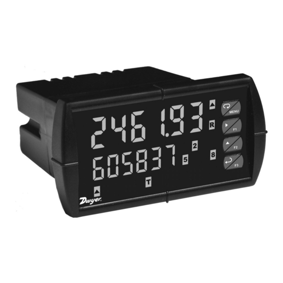
Bulletin: L-APM Analog Panel Meter Series APM Instruction Manual 0-20 mA, 4-20 mA, 0-5 V, 1-5 V, 10 V Inputs NEMA 4X, IP65 Front Universal 85-265 VAC, or 12/24 VDC Input Power Models Large Dual-Line 6-Digit Display, 0.60" & 0.46"... -
Page 2: Limited Warranty
Anyone using this product for such applications does so at his/her own risk. Dwyer Instruments, Inc. shall not be held liable for damages resulting from such improper use. Limited Warranty Dwyer Instruments, Inc. -
Page 3: Table Of Contents
Analog Panel Meter Instruction Manual Table of Contents INTRODUCTION ------------------------------------------------------------- 7 ORDERING INFORMATION ---------------------------------------------- 7 SPECIFICATIONS ----------------------------------------------------------- 8 General ------------------------------------------------------------------------------- 8 Process Input ---------------------------------------------------------------------- 9 Rate/Totalizer -------------------------------------------------------------------- 10 Relays ------------------------------------------------------------------------------ 11 Isolated 4-20 mA Transmitter Output ------------------------------------ 12 ... - Page 4 Analog Panel Meter Instruction Manual Reset Menu (reset) ------------------------------------------------------------ 34 Control Menu (Contrl) -------------------------------------------------------- 34 Setting Up the Rate/Totalizer Meter (setup) --------------------------- 35 Setting the Input Signal (input) ------------------------------------------ 36 Setting the Totalizer Features (total) ---------------------------------- 36 ...
- Page 5 Analog Panel Meter Instruction Manual Acknowledging Relays ------------------------------------------------------ 63 Pump Alternation Control Applications (Altern) --------------------- 64 Setting Up the Interlock Relay (Force On) Feature ------------------ 67 Scaling the 4-20 mA Analog Output (Aout) ---------------------------- 68 Setting Up the Password (pass) ------------------------------------------- 69 ...
- Page 6 Analog Panel Meter Instruction Manual Table of Figures Figure 1: 1/8 DIN Panel Cutout and Mounting ........16 Figure 2: Meter Dimensions - Side View ..........17 Figure 3: Meter Dimensions - Top View ..........17 Figure 4: Jumper Configuration for 12/24 VDC Power ..... 18 ...
-
Page 7: Introduction
Analog Panel Meter Instruction Manual INTRODUCTION The APM is a multipurpose, easy to use rate/totalizer ideal for flow rate, total, and control applications. It accepts current and voltage signals (e.g. 4-20 mA, 0-10 V). Three of the front panel buttons can be custom-programmed for specific opera- tion. -
Page 8: Specifications
Analog Panel Meter Instruction Manual SPECIFICATIONS Except where noted all specifications apply to operation at +77°F (+25°C). General DISPLAY Main display: 0.6" (15 mm) high, red LEDs Second display: 0.46" (12 mm) high, red LEDs 6 digits: each (-99999 to 999999), with lead zero blanking. DISPLAY Eight user selectable intensity levels. -
Page 9: Process Input
Analog Panel Meter Instruction Manual NORMAL MODE Greater than 60 dB at 50/60 Hz. REJECTION ISOLATION 4 kV input/output-to-power line. 500 V input-to-output or output-to-P+ supply. OVERVOLTAGE Installation Overvoltage Category II: CATEGORY Local level with smaller transient overvoltages than Installa- tion Overvoltage Category III. -
Page 10: Rate/Totalizer
Analog Panel Meter Instruction Manual DECIMAL POINT Up to five decimal places or none: d. d dddd, d. d ddd, d. d dd, d. d d, d. d , dddddd. CALIBRATION Input Minimum Span RANGE Range Input 1 & Input 2 4-20 mA 0.15 mA 10 V... -
Page 11: Relays
Analog Panel Meter Instruction Manual PROGRAMMA- 0.1 and 999.9 seconds; applied to the first relay assigned to BLE DELAY total or grand total. ON RELEASE If the meter is programmed to reset total to zero automati- cally when the preset is reached, then a delay will occur before the total is reset. -
Page 12: Isolated 4-20 Ma Transmitter Output
Analog Panel Meter Instruction Manual TIME DELAY 0 to 999.9 seconds, on & off relay time delays Programmable and independent for each relay. FAIL-SAFE Programmable and independent for each relay. OPERATION Note: Relay coil is energized in non-alarm condition. In case of power failure, relay will go to alarm state. AUTO When power is applied to the meter, relays will reflect the INITIALIZATION... -
Page 13: Modbus ® Rtu Serial Communications
TIMEOUT TURN AROUND Less than 2 ms (fixed). DELAY ® Note: Refer to the Modbus Register Tables located at www.dwyer-inst.com for details. PMA-12 Digital Input & Output Expansion Module CHANNELS 4 digital inputs & 4 digital outputs per module. SYSTEM Up to 2 modules for a total of 8 inputs &... -
Page 14: Compliance Information
Analog Panel Meter Instruction Manual COMPLIANCE INFORMATION Safety UL & c-UL LISTED USA & Canada UL 508 Industrial Control Equipment UL FILE NUMBER E212517 FRONT PANEL UL Type 4X, NEMA 4X, IP65; panel gasket provided LOW VOLTAGE EN 61010-1:2001 DIRECTIVE Safety requirements for measurement, control, and laboratory use Electromagnetic Compatibility... -
Page 15: Safety Information
Testing was conducted on APM meters installed through the covers of grounded metal enclosures with cable shields grounded at the point of entry representing installations designed to optimize EMC performance. Declaration of Conformity available at www.dwyer-inst.com. SAFETY INFORMATION CAUTION: Read complete WARNING: Risk of... -
Page 16: Installation
Analog Panel Meter Instruction Manual INSTALLATION There is no need to remove the meter from its case to complete the installation, wiring, and setup of the meter for most applica- tions. Instructions are provided for setting up a 12/24 VDC po- wered meter to operate from 12 VDC and for changing the transmitter power supply to output 5 or 10 VDC instead of 24 VDC, see page 18. -
Page 17: Figure 2: Meter Dimensions - Side View
Analog Panel Meter Instruction Manual Mounting Dimensions 1.76" (45 mm) 2.45" (62 mm) 4.77" 0.59" (121 mm) (15 mm) 5.05" (128 mm) Figure 2: Meter Dimensions - Side View 4.17" (106 mm) 3.61" (92 mm) 4.68" (119 mm) Figure 3: Meter Dimensions - Top View... -
Page 18: Configuration For 12 Or 24 Vdc Power Option
Analog Panel Meter Instruction Manual Configuration for 12 or 24 VDC Power Option Do not exceed voltage rating of the selected configuration. Warning! Meters equipped with the 12/24 VDC power option are shipped from the factory ready to operate from 24 VDC. To configure the meter for 12 VDC power: Remove all the connectors. -
Page 19: Transmitter Supply Voltage Selection (P+, P-)
Analog Panel Meter Instruction Manual Transmitter Supply Voltage Selection (P+, P-) All meters, including models equipped with the 12/24 VDC power option, are shipped from the factory configured to provide 24 VDC power for the transmitter or sensor. If the transmitter requires 5 or 10 VDC excitation, the internal jumper J4 must be configured accordingly. -
Page 20: Connectors Labeling
The connectors’ label, affixed to the meter, shows the location of all con- nectors available with requested configuration. Do not connect any equipment other than Dwyer Instruments, Inc.’s expansion modules, cables, or meters to the RJ45 M-LINK connector. Otherwise damage will occur Warning! to the equipment and the meter. -
Page 21: Signal Connections
Analog Panel Meter Instruction Manual Signal Connections Signal connections are made to a five-terminal connector labeled SIGNAL on Figure 6. The COM (common) terminal is the return for the 4-20 mA and the 10 V input signals. Current and Voltage Connections The following figures show examples of current and voltage connections. -
Page 22: Modbus ® Rtu Serial Communications
Analog Panel Meter Instruction Manual INPUT SIGNAL INPUT SIGNAL Signal 3-Wire Voltage Voltage Transducer Signal Figure 10: Voltage Input Connections The meter is capable of accepting any voltage from -10 VDC to +10 VDC. ® Modbus RTU Serial Communications Serial communications connection is made to an RJ45 connector labeled M-LINK on Figure 6. -
Page 23: Switching Inductive Loads
Figure 13: Low Voltage DC Loads Protection RC Networks Available from Dwyer Instruments, Inc. RC networks are available from Dwyer Instruments, Inc. and should be applied to each relay contact switching an inductive load. Part number: PMA-09. Note:... -
Page 24: 4-20 Ma Output Connections
Analog Panel Meter Instruction Manual 4-20 mA Output Connections Connections for the 4-20 mA transmitter output are made to the connec- tor terminals labeled MA OUT. The 4-20 mA output may be powered internally or from an external power supply. 24 V 24 V MA OUT... -
Page 25: External Relay & Digital I/O Connections
Analog Panel Meter Instruction Manual External Relay & Digital I/O Connections The relay and the digital I/O expansion modules PMA-11 & PMA-12 are connected to the meter using a CAT5 cable provided with each module. The two RJ45 connectors on the expansion modules are identical and interchangeable;... -
Page 26: Interlock Relay Feature
Analog Panel Meter Instruction Manual 5 VDC DI 1-4 DO 1-4 Figure 17: Digital I/O Module Connections Interlock Relay Feature As the name implies, the interlock relay feature reassigns one, or more, alarm/control relays for use as interlock relay(s). Interlock contact(s) are wired to digital input(s) and trigger the interlock relay. -
Page 27: Setup And Programming
Analog Panel Meter Instruction Manual SETUP AND PROGRAMMING The meter is factory calibrated prior to shipment to read in milliamps and volts depending on the input selection. The calibration equipment is certified to NIST standards. Overview There are no jumpers to set for the meter input selection. Setup and programming is done through the front panel buttons. -
Page 28: Front Panel Buttons And Status Led Indicators
Analog Panel Meter Instruction Manual Front Panel Buttons and Status LED Indicators Button Description Status Symbol Menu Alarm 1 – 8 indicator Right arrow/F1 Rate indicator Total indicator or Up arrow/F2 Flashing: Tare Enter/F3 Grand Total indicator Note: Total overflow ▲... -
Page 29: Display Functions And Messages
Analog Panel Meter Instruction Manual Display Functions and Messages The meter displays various functions and messages during setup, pro- gramming, and operation. The following table shows the main menu functions and messages in the order they appear in the menu. Display Parameter Action/Setting Description... - Page 30 Analog Panel Meter Instruction Manual Display Parameter Action/Setting Description Inp 2 Input 2 Calibrate input 2 signal or program input 2 value (up to 32 points). Display 2 Program display 2 value (up to 32 points). Dis 2 Error Error, calibration not successful, check Error signal or programmed value.
- Page 31 Analog Panel Meter Instruction Manual Display Parameter Action/Setting Description RSt 1 Reset 1 Program reset point 1. RLY 2 Relay 2 Relays 2-8 setup Note: Relays 5-8 are shown, only if ex- pansion relay module is installed. Enter Fail-safe menu. FaiLSF Fail-safe FLS 1...
- Page 32 Analog Panel Meter Instruction Manual Display Parameter Action/Setting Description GT CF Grand total Program grand total conversion factor. conversion factor Grand total Program grand total rest mode: auto or GT rst reset manual Automatic Press Enter to set automatic total reset. Auto Time delay Program time delay for total auto reset.
-
Page 33: Main Menu
Analog Panel Meter Instruction Manual Main Menu The main menu consists of the most commonly used functions: Reset, Control, Setup , and Password . Press Menu button to enter Programming Mode then press the Up Arrow button to scroll main menu. ... -
Page 34: Setting Numeric Values
Analog Panel Meter Instruction Manual Setting Numeric Values The numeric values are set using the Right and Up arrow buttons. Press Right arrow to select next digit and Up arrow to increment digit value. The digit being changed is displayed brighter than the rest. Press and hold up arrow to auto-increment the display value. -
Page 35: Setting Up The Rate/Totalizer Meter (Setup)
Analog Panel Meter Instruction Manual Setting Up the Rate/Totalizer Meter (setup) The Setup menu is used to select: Input signal the meter will accept. Enable or disable totalizer features. Decimal point position. Display parameter and intensity. Relay operation. 4-20 mA analog output scaling. Press the Enter button to access any menu or press Up Arrow button to scroll through choices. -
Page 36: Setting The Input Signal (Input)
1. The totalizer continues working in the background. 2. When selecting "no" for Total, the meter now functions as a Process Meter. We strongly suggest that you download and use the instruction manual from our website (www.dwyer-inst.com) while in this mode of operation. -
Page 37: Dual-Scale For Level Application
Analog Panel Meter Instruction Manual Dual-Scale for Level Application The analog input can be displayed in two different scales, by enabling the dual-scale feature (LEVEL) in the Setup Input menu, see page 36. To enable the dual-scale feature for level applications you must select LEVEL in the Input selection menu. -
Page 38: Setting The Decimal Point (Dec Pt)
Analog Panel Meter Instruction Manual Setting the Decimal Point (dEc pt) The decimal point may be set with up to five decimal places or with no decimal point at all. The rate, total, and grand total decimal points are independent. Pressing the Right Arrow moves the decimal point one place to the right until no decimal point is displayed then it moves to the leftmost position. -
Page 39: Programming The Rate/Totalizer (Prog)
Analog Panel Meter Instruction Manual Programming the Rate/Totalizer (prog) It is very important to read the following information, before proceeding to program the meter: The meter is factory calibrated prior to shipment to read in milliamps and volts depending on the input selection. The calibration equip- ment is certified to NIST standards. -
Page 40: Multi-Point Calibration & Scaling
Panel Meter Pro Software The meter can also be programmed using the PC-based Panel Meter Pro software available for free download at www. dwyer-inst.com. Data logging for one meter at the time is available with Panel Meter Pro software. More advanced data acquisition may be accomplished by us- ing any Modbus RTU compliant software. -
Page 41: Scaling The Meter (Scale)
Analog Panel Meter Instruction Manual Scaling the Meter (SCALE) The process inputs (4-20 mA and 10 VDC) can be scaled to display the process variable in engineering units. A signal source is not needed to scale the meter; simply program the inputs and corresponding display values. - Page 42 Analog Panel Meter Instruction Manual Error Message (Error) An error message indicates that the calibration or scaling process was not successful. After the error message is displayed, the meter reverts to input 2 during calibration or scaling and to input 1 during internal calibration, allowing the appropriate input signal to be applied or programmed.
-
Page 43: Time Base, Total Conversion Factor & Total Reset
Analog Panel Meter Instruction Manual Time Base, Total Conversion Factor & Total Reset The time base, total conversion factor, and total reset menus are located in the Program menu. The total and grand total have their own independent settings. This means that one can be displaying the value in gallons while the other displays in million gallons, liters, m , etc. -
Page 44: Calibrating The Meter With External Source (Cal)
Analog Panel Meter Instruction Manual Calibrating the Meter with External Source (Cal) To scale the meter without a signal source refer to Scaling the Meter ( SCALE ) page 41. The meter can be calibrated to display the process variable in engineer- ing units by applying the appropriate input signal and following the cali- bration procedure. -
Page 45: Setting The Display Parameter & Intensity (Dsplay)
Analog Panel Meter Instruction Manual Setting the Display Parameter & Intensity (dsplay) The main display ( Big ) can be programmed to display: Rate value. Total or grand total. Relay set points. Max & min values. ® Modbus input. Display rate and units The small display ( Little ) can be programmed to display: Rate value. -
Page 46: Display Setup Menu
Analog Panel Meter Instruction Manual Display Setup Menu Press the Up Arrow to change selection. Press Enter to accept setting. Press Menu to exit programming. After setting up the input and the display, press the Menu button to exit programming and skip the rest of the setup menu. -
Page 47: Character Set For Engineering Units Display (D Unit)
Analog Panel Meter Instruction Manual Character Set for Engineering Units Display (d unit) The small display can be programmed to show engineering units or cus- tom legends using the following 7-segment character set: Display Character Display Character Space Degree *Degree symbol (special non-ASCII character used) The letters “m”... -
Page 48: Setting The Relay Operation (Relay)
Analog Panel Meter Instruction Manual Setting the Relay Operation (relay) This menu is used to set up the operation of the relays. CAUTION! During setup, the relays do not follow the input and they will remain in the state found prior to entering the Relay menu. Relay assignment Rate for low and high alarm. -
Page 49: Relay Assignment (Assign)
Analog Panel Meter Instruction Manual relay setup Assign Failsf delay break relay relay relay relay relay Asign1 break1 A s s i g n r l y 1 F a i l s f delay b r e a k ignore rly 1 F l s 1... -
Page 50: Setting The Relay Action
Analog Panel Meter Instruction Manual Setting the Relay Action Operation of the relays is programmed in the Action menu. The relays may be set up for any of the following modes of operation: Automatic reset (non-latching). Automatic + manual reset at any time (non-latching). Latching (manual reset only, at any time). -
Page 51: Programming Set And Reset Points
Analog Panel Meter Instruction Manual Programming Set and Reset Points High alarm indication: program set point above reset point. Low alarm indication: program set point below reset point. The deadband is determined by the difference between set and reset points. Minimum deadband is one display count. If the set and reset points are programmed with the same value, the relay will reset one count below the set point. -
Page 52: Relay And Alarm Operation Diagrams
Analog Panel Meter Instruction Manual Relay and Alarm Operation Diagrams The following graphs illustrate the operation of the relays, status LEDs, and ACK button. High Alarm Operation (Set > Reset) For Manual reset mode, ACK can be pressed anytime to turn "off" relay. To detect a new alarm condition, the signal must go below the set point, and then go above it. -
Page 53: Low Alarm Operation (Set < Reset)
Analog Panel Meter Instruction Manual Low Alarm Operation (Set < Reset) Input Reset de-energized energized Relay Automatic (non-latching) Relay pressed Automatic or Manual (non-latching) Relay pressed Manual (latching) Relay pressed Manual only after passing above Reset (latching with clear) For Manual reset mode, ACK can be pressed anytime to turn "off" relay. For relay to turn back “on”, signal must go above set point and then go below it. -
Page 54: High Alarm With Fail-Safe Operation (Set > Reset)
Analog Panel Meter Instruction Manual High Alarm with Fail-Safe Operation (Set > Reset) Input Reset de-energized energized Relay Automatic (non-latching) Relay pressed Automatic or Manual (non-latching) Relay pressed Manual (latching) Relay pressed Manual only after passing below Reset (latching with clear) Note: Relay coil is energized in non-alarm condition. -
Page 55: Low Alarm With Fail-Safe Operation (Set < Reset)
Analog Panel Meter Instruction Manual Low Alarm with Fail-Safe Operation (Set < Reset) Input Reset de-energized energized Relay Automatic (non-latching) Relay pressed Automatic or Manual (non-latching) Relay pressed Manual (latching) Relay pressed Manual only after passing above Reset (latching with clear) Note: Relay coil is energized in non-alarm condition. -
Page 56: Pump Alternation Control Operation
Analog Panel Meter Instruction Manual... -
Page 57: Rate Relay Sampling Operation
Analog Panel Meter Instruction Manual Rate Relay Sampling Operation Input Reset Sample Sample Sample Time Time Time Relay When the signal crosses the set point, the relay trips and the sample time starts. After the sample time has elapsed, the relay resets. The cycle repeats every time the set point is crossed, going up for high alarms and going down for low alarms. -
Page 58: Signal Loss Or Loop Break Relay Operation
Analog Panel Meter Instruction Manual Signal Loss or Loop Break Relay Operation The following graph shows the loop break operation for a high alarm relay. Input Reset de-energized energized Relay Loop Break = Ignore Relay Loop Break = Off Relay Loop Break = On When the meter detects a break in the 4-20 mA loop, the relay will go to one of the following selected actions:... -
Page 59: Time Delay Operation
Analog Panel Meter Instruction Manual Time Delay Operation The following graphs show the operation of the time delay function. Input Reset <Tdelay <Tdelay >=Tdelay Relay On Time Delay Input Reset <Tdelay <Tdelay >=Tdelay Relay Off Time Delay When the signal crosses the set point, the On time delay timer starts and the relay trips when the time delay has elapsed. -
Page 60: Relay Operation Details
Analog Panel Meter Instruction Manual Relay Operation Details Overview The relay capabilities of the meter expand its usefulness beyond simple indication to provide users with alarm and control functions. These capa- bilities include front panel alarm status LEDs as well as either 2 or 4 op- tional internal relays and/or 4 external relays expansion module. -
Page 61: Front Panel Leds
Analog Panel Meter Instruction Manual Front Panel LEDs The LEDs on the front panel provide status indication for the following: Status Status Alarm 1 Alarm 5 Alarm 2 Alarm 6 Alarm 3 Alarm 7 Alarm 4 Alarm 8 The meter is supplied with four alarm points that include front panel LEDs to indicate alarm conditions. -
Page 62: Non-Latching Relay (Auto)
Analog Panel Meter Instruction Manual Non-Latching Relay (Auto) Automatic reset only Condition Relay Normal Alarm Ack (No effect) Normal In this application, the meter is set up for automatic reset (non-latching relay). Acknowledging the alarm while it is still present has no effect on either the LED or the relay. -
Page 63: Latching Relay (Lt-Clr)
Analog Panel Meter Instruction Manual Latching Relay (Lt-Clr) Manual reset only after alarm condition has cleared Condition Relay Normal Alarm Ack (No effect) Normal In this application, the meter is set up for manual reset only after the signal passes the reset point (alarm condition has cleared). Acknowledg- ing the alarm while it is still present has no effect on either the LED or the relay. -
Page 64: Pump Alternation Control Applications (Altern)
Analog Panel Meter Instruction Manual Pump Alternation Control Applications (Altern) For pump control applications where two or more similar pumps are used to control the level of a tank or a well, it is desirable to have all the pumps operate alternately. This prevents excessive wear and overheat- ing of one pump over the lack of use of the other pumps. - Page 65 Analog Panel Meter Instruction Manual Application #2: Pump Alternation Using Relays 3 & 4 1. Relays 1 and 2 are set up for low and high alarm indication. 2. Relays 3 and 4 are set up for pump alternation. Set and Reset Point Programming Relay Set Point Reset Point...
- Page 66 Analog Panel Meter Instruction Manual If the backup pump is not able to keep up, and the level reaches 7000 gallons, relay #4 transfers and starts the main pump as well. Relay #2 trips the High Level Alarm at 7500 gallons and resets at 6900 gallons.
-
Page 67: Setting Up The Interlock Relay (Force On) Feature
Analog Panel Meter Instruction Manual Setting Up the Interlock Relay (Force On) Feature Relays 1-4 can be set up as interlock relays. To set up the relays for the interlock feature: 1. Access the Setup – Relay – Action menu and set the action to off. setup relay rly 1... -
Page 68: Scaling The 4-20 Ma Analog Output (Aout)
Analog Panel Meter Instruction Manual Scaling the 4-20 mA Analog Output (Aout) The 4-20 mA analog output can be scaled to provide a 4-20 mA signal for any display range selected. No equipment is needed to scale the analog output; simply program the display values to the corresponding mA output signal. -
Page 69: Setting Up The Password (Pass)
Analog Panel Meter Instruction Manual Setting Up the Password (pass) The Password menu is used for programming three levels of security to prevent unauthorized changes to the programmed parameter settings and to program the non-resettable totalizer. Pass 1: Allows use of function keys and digital inputs. Pass 2: Allows use of function keys, digital inputs and editing set/reset points. -
Page 70: Total Reset Password & Non-Resettable Total
Analog Panel Meter Instruction Manual Total Reset Password & Non-Resettable Total The total and the grand total can be password-protected to pre- vent unauthorized total resets. The grand total can be programmed as a non-resettable total by entering the password “050873”. Once the Grand Total has been programmed as “non- resettable”... -
Page 71: Making Changes To A Password Protected Meter
Analog Panel Meter Instruction Manual Making Changes to a Password Protected Meter If the meter is password protected, the meter will display the message Locd ( Locked ) when the Menu button is pressed. Press the Enter button while the message is being displayed and enter the correct password to gain access the menu. -
Page 72: Advanced Features Menu
Analog Panel Meter Instruction Manual Advanced Features Menu To simplify the setup process, functions not needed for most applications are located in the Advanced Features menu. Press and hold the Menu button for three seconds to access the ad- vanced features of the meter. Run Mode Press &... -
Page 73: Advanced Features Menu & Display Messages
Analog Panel Meter Instruction Manual Advanced Features Menu & Display Messages The following table shows the functions and messages of the Advanced Features menu in the order they appear in the menu. Display Parameter Action/Setting Filter Set noise filter value. filtr Set filter bypass value. - Page 74 Analog Panel Meter Instruction Manual Display Parameter Action/Setting Program mA output for display overrange. O-rang Overrange u-rang Underrange Program mA output for display underrange. Loop Break Set relay condition if loop break detected. Break Force Force analog output value for loop break. Force Ignore Ignore loop break condition.
- Page 75 Analog Panel Meter Instruction Manual Display Parameter Action/Setting Copy function completed. done Done Diag Diagnostics Display parameter settings. Filter Display filter selection. Filter Input Input selection. Input Filter Set noise filter level. Filter Bypass Set filter bypass level. bypass Function Function selected.
-
Page 76: Noise Filter (Filter)
Analog Panel Meter Instruction Manual Noise Filter (filter) The noise filter is available for unusually noisy signals that cause an un- stable process variable display. The noise filter averages the input signal over a certain period. The filter level determines the length of time over which the signal is averaged. -
Page 77: Modbus ® Rtu Serial Communications (Serial)
RS-232 or RS-422/485 adapter option is required; see Ordering Informa- tion on page 7 for details. Do not connect any equipment other than Dwyer Instruments, Inc.’s expansion modules, cables, or meters to the RJ45 M-LINK connector. Otherwise damage will occur Warning! to the equipment and the meter. -
Page 78: Select Menu (Select)
Analog Panel Meter Instruction Manual Select Menu (SElEct) The Select menu is used to select the input conditioner applied to the input (linear, square root, programmable exponent, or round horizontal tank), low-flow cutoff, and analog output programming. The multi-point linearization is part of the linear function selection. Signal Input Conditioning (Functn) The Function menu is used to select the signal input conditioner applied to the input: linear, square root, programmable exponent, or... - Page 79 Analog Panel Meter Instruction Manual Square Root Linearization (Square) The square root function can be used to linearize the signal from a diffe- rential pressure transmitter and display flow rate in engineering units. Programmable Exponent Linearization (Prog E) The programmable exponent can be used to linearize the signal from level transmitters in open-channel flow applications using weirs and flumes.
- Page 80 Analog Panel Meter Instruction Manual Round Horizontal Tank Linearization (rHt) This function automatically calculates the volume in a round horizontal tank with flat ends. Set the display for the desired decimal point and engineering units be- fore entering the round horizontal tank function. Select units, inches or cm for the tank dimension.
-
Page 81: Low-Flow Cutoff (Cutoff)
Analog Panel Meter Instruction Manual Low-Flow Cutoff (CutofF) The low-flow cutoff feature allows the meter to be programmed so that the often-unsteady output from a differential pressure transmitter, at low flow rates, always displays zero on the meter. The cutoff value may be programmed from 0 to 999999. The meter will display zero below the cutoff value. -
Page 82: Programmable Function Keys User Menu (User)
Analog Panel Meter Instruction Manual Programmable Function Keys User Menu (user) The User menu allows the user to assign the front panel function keys F1, F2, F3 and up to eight digital inputs to access most of the menus or to activate functions immediately (e.g. -
Page 83: Tare (Tare)
Analog Panel Meter Instruction Manual Tare (tare) The tare function zero’s out the display. In the case of scale weight, tare is used to eliminate container weight and provide net weight readings. There are two tare functions; Capture Tare and Reset Tare. This function may only be used when Total ( total ) is set to No ( no ). - Page 84 Analog Panel Meter Instruction Manual The meter displays either current calibration ( C CAL ) or voltage cali- bration ( v CAL ), according to the input setup. Press Enter to start the calibration process. Example of Internal Calibration for current input: The meter displays low input current message ( C lo ).
- Page 85 Analog Panel Meter Instruction Manual Tips: Low and high input signals can be any valid value within the range of the meter. Observe minimum input span requirements between input 1 and input 2. Low input should be less than high input signal. Error Message ( Error ) An error message indicates that the calibration or scaling process was not successful.
-
Page 86: Meter Copy Function (Copy)
Analog Panel Meter Instruction Manual Meter Copy Function (Copy) The Copy function is used to copy (or clone) all the settings from one meter to other meters requiring exactly the same setup and program- ming ( i.e . type of input, scaling, decimal point, filter, bypass, etc.). Only the PMA-02 meter copy cable must be used for meter-to-meter interfacing. - Page 87 Analog Panel Meter Instruction Manual Meter Copy or Cloning Instructions Do not connect the two meters to the same signal source while cloning. Internal calibration may Caution! be affected. Connect two meters using a PMA-02 meter copy cable. Use PMA-02 meter copy cable only! Using standard CAT5 or other cable will cause damage to both meters.
-
Page 88: Meter Operation
Analog Panel Meter Instruction Manual METER OPERATION The meter is capable of accepting current (0-20 mA, 4-20 mA) and vol- tage signals (0-5 V, 1-5 V, 0-10 V, 10 V) and displaying these signals in engineering units from -99999 to 999999 ( e.g. a 4-20 mA signal could be displayed as -50.000 to 50.000). -
Page 89: Maximum/Minimum Readings
Analog Panel Meter Instruction Manual Maximum/Minimum Readings The max & min readings (peak & valley) reached by the process can be displayed either continuously or momentary: Display briefly by assigning to the F1-F3 function keys or to the digi- tal inputs in the User menu. Display continuously by assigning either display to max/min through the Display menu. -
Page 90: Troubleshooting
Analog Panel Meter Instruction Manual TROUBLESHOOTING The rugged design and the user-friendly interface of the meter should make it unusual for the installer or operator to refer to this section of the manual. However, due to the many features and functions of the meter, it’s possible that the setup of the meter does not agree with what an op- erator expects to see. -
Page 91: Reset Meter To Factory Defaults
Analog Panel Meter Instruction Manual Reset Meter to Factory Defaults When the parameters have been changed in a way that is difficult to determine what’s happening, it might be better to start the setup process from the factory defaults. Instructions to load factory defaults: Enter the Advanced Features menu. -
Page 92: Factory Defaults & User Settings
Analog Panel Meter Instruction Manual Factory Defaults & User Settings The following table shows the factory setting for most of the programma- ble parameters on the meter. Next to the factory setting, the user may record the new setting for the particular application. Model: ______________ S/N: _______________ Date: _________ Parameter... - Page 93 Analog Panel Meter Instruction Manual Parameter Display Default Setting User Setting Total reset Manual T rst Grand total time base Second GT tb Grand total 1.000 T CF conversion factor Grand total reset Manual T rst Relay 1 assignment Total Asign1 Relay 2 assignment Total...
- Page 94 Analog Panel Meter Instruction Manual Parameter Display Default Setting User Setting Fail-safe relay 4 Fls 4 On delay relay 1 0.0 sec On 1 Off delay relay 1 0.0 sec Off 1 On delay relay 2 0.0 sec On 2 Off delay relay 2 0.0 sec Off 2...
- Page 95 Analog Panel Meter Instruction Manual Parameter Display Default Setting User Setting Slave ID (Address) Slave Id Baud rate 9600 baud Transmit delay 10 ms Tr dly Parity Even Parity Byte-to-byte timeout 010 (0.1 sec) t-byt F1 function key Reset max & min F2 function key Big display: Max (Hi) F3 function key...
-
Page 96: Troubleshooting Tips
Analog Panel Meter Instruction Manual Troubleshooting Tips Symptom Check/Action Check power at power connector. No display at all Meter is password-protected, enter Not able to change setup or pro- correct six-digit password to unlock. gramming, Locd is displayed Check: Meter displays error message Signal connections. -
Page 97: Alphabetical List Of Display Functions & Messages
Analog Panel Meter Instruction Manual Alphabetical List of Display Functions & Messages Display Parameter Action/Setting Description 20 mA output Enter mA output value read by milliamp 20 mA meter with at least 0.001 mA resolution. 4 mA 4 mA output Enter mA output value read by milliamp meter with at least 0.001 mA resolution. - Page 98 Analog Panel Meter Instruction Manual Display Parameter Action/Setting Description Bypass Set filter bypass value. bypASs Current Calibrating 4-20 mA current input (internal C CAL calibration reference source used for scaling the input). Current high Calibrate high current input (e.g. 20 mA). C Hi Current low Calibrate low current input (e.g.
- Page 99 Analog Panel Meter Instruction Manual Display Parameter Action/Setting Description Display Set display intensity level from 1 to 8. d-Inty intensity Dis 1 Display 1 Program display 1 value. Display 2 Program display 2 value. Dis 2 Disable Disable function key. disabl Delay 1 Enter relay 1 time delay setup.
- Page 100 Analog Panel Meter Instruction Manual Display Parameter Action/Setting Description Grand total time Program grand total time base. GT tb base Gtotal Grand total Set or enter password for manual reset. password Internal source Enter internal source calibration (used for ICal scaling the meter without a signal source.
- Page 101 Analog Panel Meter Instruction Manual Display Parameter Action/Setting Description 4-20 mA Set meter for 4-20 mA input. Manual To manually control. Maximum Program maximum mA output allowed. ® ® mbus Modbus Select to display Modbus input or to as- ® sign Modbus input as the analog output source.
- Page 102 Analog Panel Meter Instruction Manual Display Parameter Action/Setting Description Relay Enter the Relay menu. RELaY Reset To access the Reset menu. reset Round horizontal Set meter for round horizontal tank volume tank calculation. Right arrow Assign digital input to Right arrow button/F1. Right Relay 1 Relay 1 setup.
- Page 103 Analog Panel Meter Instruction Manual Display Parameter Action/Setting Description Reset tare Reset tare. Tarest Total conversion Program total conversion factor. T CF factor Time delay Program time delay for total auto reset. T dly Total reset Program total rest mode: auto or manual. T rst Total time base Program total time base.
- Page 104 Analog Panel Meter Instruction Manual...
-
Page 105: Figure 21:1/8 Din Panel Cutout Template
Analog Panel Meter Instruction Manual Figure 21:1/8 DIN Panel Cutout Template... - Page 106 Analog Panel Meter Instruction Manual...
- Page 107 Analog Panel Meter Instruction Manual NOTES...
- Page 108 Analog Panel Meter Instruction Manual Dwyer Instruments, Inc. PO Box 373 Michigan City, IN 46361 USA Tel. (800) 872-9141 • Fax (219) 872-9057 LIM6200DW_C SFT039 Ver 2.200 & up 06/11...
Need help?
Do you have a question about the Series APM and is the answer not in the manual?
Questions and answers