Table of Contents
Advertisement
Quick Links
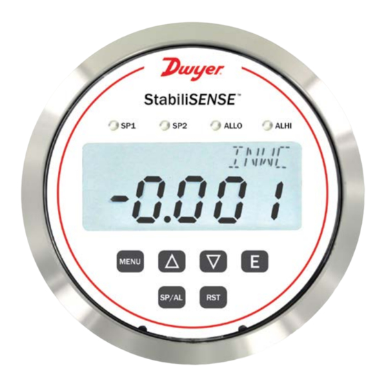
Series RPMC StabiliSENSE
Specifications - Installation and Operating Instructions
The Series RPMC StabiliSENSE
Critical Room Pressure Monitor is designed for
™
critical low differential pressure applications that require stringent pressure monitoring
and alarming. The Series RPMC can be configured to monitor positive or negative
pressure in protected environments and clean manufacturing areas. The RPMC is
a complete system with a graphic user interface which enables access to pressure,
Security, calibration, and alarm setup. The RPMC StabiliSENSE
pressure monitor has a brushed stainless steel bezel that allows for easy cleaning.
The RPMC StabiliSENSE
critical room pressure monitor has built-in status indication
™
LEDs that will appear green when between user-defined pressure set range and will
appear orange when outside of the pressure set range. 2 SPDT independent control
relays with adjustable deadbands are also provided along with a 4-20 mA process
output.
FEATURES/BENEFITS
• Long term stable pressure measurement
• 2 SPDT relays allow for capability of local alarming and alarming to control system
• Automatic or manual alarm reset
• Visual LED alarms provide immediate local alert allowing corrective action to be
taken quicker to eliminate the problem from becoming widespread
• Stores peak and valley process readings
• Same installation diameter as Magnehelic
RPMC StabiliSENSE
critical room pressure monitor
™
• Password protected setup menu ensures no errors by untrained personnel
INSTALLATION LOCATION: Select a clean, dry location free from shock and vibration
where temperature limits will not be exceeded. Distance from the transmitter to the
receiver is limited only by total loop resistance. See ELECTRICAL CONNECTIONS.
Tubing feeding pressure to the instrument can be practically any length required, but
long lengths will increase response time slightly.
POSITION: All standard models are calibrated for use in a vertical mounting position.
Standard models will perform properly at other angles but should be spanned and
zeroed in the position in which they will be used. WARM-UP: It is recommended to
power up the RPMC StabiliSENSE
™
taking measurements. This will stabilize the measurements and provide the best
accuracy.
PRESSURE CONNECTIONS: For installation convenience two sets of 1/8˝ female
NPT pressure ports are supplied. Be sure to seal the unused ports with pipe plugs,
included.
Positive Pressure - Connect tubing to HIGH PRESSURE port and vent LOW
PRESSURE port to atmosphere.
Negative (Vacuum) Pressure - Connect tubing to LOW PRESSURE port and
vent HIGH PRESSURE port to atmosphere. (When operating this device in a dusty
environment, install an optional A-331 Filter Vent Plug in the vented port to keep
interior clean).
Differential Pressure - Connect tubing from the higher source to HIGH PRESSURE
port and from the lower source to LOW PRESSURE port.
DWYER INSTRUMENTS, INC.
P.O. BOX 373 • MICHIGAN CITY, INDIANA 46360, U.S.A.
1/2 [12.70]
1-9/32
[32.54]
1/8 FEMALE
NPT LOW PRESSURE
CONNECTION
™
critical room
gage which simplifies field upgrade to
®
unit and allow a 1-hour warm-up period before
Critical Room Pressure Monitor
™
1/8 FEMALE
NPT HIGH PRESSURE
CONNECTION
11/16
[17.46]
1/8 FEMALE
NPT HIGH PRESSURE
CONNECTION
30Ø
1-3/4
[44.45]
1/2
1/8 FEMALE
[12.70]
NPT LOW PRESSURE
11/16
CONNECTION
[17.46]
[3]Ø3/16 [4.77] HOLES EQUALLY
SPACED ON A 4-1/8 [104.78] B.C.
SURFACE MOUNTING
SPECIFICATIONS
Service: Air and non-combustible, compatible gases.
Measurement Technology: Capacitance cell.
Wetted Materials: Consult factory.
Housing Material: Die cast aluminum case and SS bezel.
Accuracy: ±0.25% RSS (includes non-linearity: ±0.24%, hysteresis: ±0.05%
and non-repeatability: ±0.05%), or ±0.5% RSS (includes non-linearity: ±0.49%,
hysteresis: ±0.05% and non-repeatability: ±0.05%).
Pressure Limits: 2 psi.
Compensated Temperature Limits: 32 to 140°F (0 to 60°C).
Thermal Effects: 0.030%/°F (0.050/°C) from 77°F (25°C).
Power Requirements: 12-28 VDC, 12-28 VAC 50 to 400 Hz.
Power Consumption: 3 VA max.
Output Signal: 4-20 mA DC into 900 Ω max.
Zero and Span Adjustments: Accessible via menus.
Response Time: 8 ms.
Display: Backlit 4 digit LCD 0.4˝ height LED indicators for set point and alarm
status.
Electrical Connections: 15 pin male high density D-sub connection. 18˝ (46 cm)
cable with 10 conductors included.
Process Connections: 1/8˝ female NPT. Side or back connections.
Mounting Orientation: Mount unit in vertical plane. Size: 4-3/4˝ (120.7 mm) OD x
2-21/32 (67.5 mm).
Weight: 1.90 lb (862 g).
Agency Approvals: CE.
SWITCH SPECIFICATIONS
Switch Type: 2 SPDT relays.
Electrical Rating: 1 A @ 30 VAC/VDC.
Set Point Adjustment: Adjustable via keypad on face.
Phone: 219-879-8000
Fax: 219-872-9057
Bulletin P-RPMC
2-1/16
[52.39]
2
[50.80]
4-47/64
1.250
[120.14]
[31.75]
4-31/64
[113.79]
2-1/2
1/8
[63.50]
[3.18]
www.dwyer-inst.com
e-mail: info@dwyermail.com
Ø4 [101.60]
FACE
Advertisement
Table of Contents

Related Manuals for Dwyer Instruments StabiliSENSE RPMC Series


Summary of Contents for Dwyer Instruments StabiliSENSE RPMC Series
- Page 1 A-331 Filter Vent Plug in the vented port to keep interior clean). Differential Pressure - Connect tubing from the higher source to HIGH PRESSURE port and from the lower source to LOW PRESSURE port. DWYER INSTRUMENTS, INC. Phone: 219-879-8000 www.dwyer-inst.com P.O. BOX 373 • MICHIGAN CITY, INDIANA 46360, U.S.A.
- Page 2 MOUNTING: The RPMC StabiliSENSE critical room pressure monitor may be either WIRING The RPMC uses a standard 15 pin male high density D-Sub connector ™ panel (flush) mounted or surface mounted. available from most electronic distributors. A pre-wired 18˝ cable is included with each unit.
- Page 3 LED and Display Behavior - The RPMC StabiliSENSE critical room pressure Menu Map ™ monitor is designed to provide the room pressure status of the room being monitored to personnel with visual indication of the LED status lights and backlit 4 digit LCD. All MAIN MENUS SUB MENUS SETTINGS...
- Page 4 SETTINGS MENU Main Menu Selections (Upper Right Display Reads MAIN MENUS SUB MENUS SECr Security - Lock out access to Set Point and Alarm settings, or lock out access to all settings. OPEr Operation - Selection of Pressure engineering units. Output - Select a Single Set Point, 2 Set Points, or a Set Point and an Alarm mode of operation.
- Page 5 CtrL CtrL SPAL (Control) SUB MENU The following alarm function SUB MENUS are activated when is set to - Single set point (Alarm Type) SUB MENU - Two fully independent set points SPAL - Single set point and alarm - High alarm - Low alarm HILO (SP1 Reverse or Direct Acting) SUB MENU...
- Page 6 Return Materials Authorization number before shipping the product back for repair. Be sure to include a brief description of the problem plus any additional application notes. ©Copyright 2020 Dwyer Instruments, Inc. Printed in U.S.A. 9/20 FR# 444595-00 Rev. 1 DWYER INSTRUMENTS, INC.
Need help?
Do you have a question about the StabiliSENSE RPMC Series and is the answer not in the manual?
Questions and answers