Table of Contents
Advertisement
Quick Links
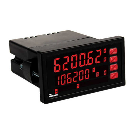
1/8 DIN Digital Panel Flow Rate/Totalizers with NEMA 4X, IP65 Front
•
0-20 mA, 4-20 mA, 0-5 V, 1-5 V, and ±10 V Inputs
•
Dual-Line 6-Digit Display, 0.6" (15 mm) & 0.46" (12 mm)
•
Isolated 24 VDC @ 200 mA Transmitter Power Supply
•
2 or 4 Relays with Interlocking Capability + Isolated 4-20 mA Output Options
•
•
Free PC-Based, On-Board, Panel Meter Pro USB Programming Software
No Assembly Required
•
•
Display Rate & Total at the Same Time
Rate in Units per Second, Minute, Hour, or Day
•
•
Total, Grand Total or Non-Resettable Grand Total
Front Panel or Remote Total Reset
•
•
Password Protection for Total Reset
Total Stored in Non-Volatile Memory
•
•
Assign Any Relay for Rate or Total
4-20 mA Output for Rate or Total
•
•
Sampling Relay
Display Open Channel Flow with Programmable Exponent Feature
•
•
32-Point Linearization & Square Root Extraction
Optional SunBright Display Models for Outdoor Applications
•
•
Operating Temperature Range: -40 to 65°C (-40 to 149°F)
UL & C-UL Listed. E160849; 508 Industrial Control Equipment
•
Input Power Options: 85-265 VAC / 90-265 VDC or 12-24 VDC / 12-24 VAC
•
Programmable Display, Function Keys & Digital Input
•
External 4-Relay & Digital I/O Modules
•
RS-232 & RS-485 Serial Communication Options with Modbus RTU
•
Wide Assortment of NEMA 4X Enclosures for up to Ten Meters
•
3-Year Warranty
•
DWYER INSTRUMENTS, INC.
P.O. BOX 373 • MICHIGAN CITY, IN 46360, U.S.A.
Series APM Analog Panel Meter
Instruction Manual
Phone: 219/879-8000
dwyer-inst.com
Fax: 219/872-9057
e-mail: info@dwyermail.com
Bulletin: L-APM
Advertisement
Table of Contents

Related Manuals for Dwyer Instruments APM Series


Summary of Contents for Dwyer Instruments APM Series
- Page 1 RS-232 & RS-485 Serial Communication Options with Modbus RTU • Wide Assortment of NEMA 4X Enclosures for up to Ten Meters • 3-Year Warranty • DWYER INSTRUMENTS, INC. Phone: 219/879-8000 dwyer-inst.com P.O. BOX 373 • MICHIGAN CITY, IN 46360, U.S.A. Fax: 219/872-9057 e-mail: info@dwyermail.com...
- Page 2 When using the Micro USB connection, DO NOT apply AC or DC Anyone using this product for such applications power to the meter. does so at his/her own risk. Dwyer Instruments, Inc. shall not be held liable for damages resulting The easiest and quickest way to program your MPM from such improper use.
-
Page 3: Table Of Contents
Series APM Analog Panel Meter Instruction Manual Table of Contents Introduction ......................6 Using the APM Like an MPM Process Meter ..........6 Ordering Information ..................6 Specifications ..................... 7 General ......................7 Process Input ....................8 Rate/Totalizer ....................8 Relays ...................... - Page 4 Series APM Analog Panel Meter Instruction Manual Relay and Alarm Operation Diagrams ............28 High Alarm Operation (Set > Reset) .............. 28 Low Alarm Operation (Set < Reset) ............28 High Alarm with Fail-Safe Operation (Set > Reset) ........28 Low Alarm with Fail-Safe Operation (Set <...
- Page 5 Series APM Analog Panel Meter Instruction Manual Table of Figures Figure 1: 1/8 DIN Panel Cutout and Mounting ..........12 Figure 2. Meter Dimensions - Side View ............12 Figure 3. Meter Dimensions - Top View ............12 Figure 4: Transmitter Supply Voltage Selection ..........14 Figure 5.
-
Page 6: Introduction
Series APM Analog Panel Meter Instruction Manual Introduction Ordering Information Standard Models Front, back and in between, the APM meter boasts specifications, features and functionality that make it 85-265 VAC 12-24 VDC Options Installed the only 1/8 DIN analog input flow rate/totalizer you Model Model will ever need. -
Page 7: Specifications
Series APM Analog Panel Meter Instruction Manual Specifications Isolation 4 kV input/output-to-power line 500 V input-to-output or output-to-P+ supply Except where noted all specifications apply to Overvoltage Installation Overvoltage Category II: operation at +25°C. Category Local level with smaller transient overvoltages than Installation Overvoltage General Category III. -
Page 8: Process Input
Series APM Analog Panel Meter Instruction Manual Process Input Total Display 0 to 999,999; automatic lead zero blanking. & Total “T” LED is illuminated while displaying total Overflow or grand total. Inputs Field selectable: 0-20 mA, 4-20 mA Up to 999,999,999 with total-overflow ±10 V (0-5 V, 1-5 V, 0-10 V) feature. -
Page 9: Relays
Series APM Analog Panel Meter Instruction Manual Relays Isolated 4-20 mA Transmitter Output Rating 2 or 4 SPDT (Form C) internal and/or 4 SPST (Form A) external; rated 3 A Output Source Rate/process, total, grand total, max, min, @ 30 VDC and 125/250 VAC resistive load; set points 1-8, or manual control mode 1/14 HP (≈... -
Page 10: Usb Connection
Series APM Analog Panel Meter Instruction Manual USB Connection Modbus ® RTU Serial Communications Function Programming only Compatibility USB 2.0 Standard, Compliant Slave Id 1 – 247 (Meter address) Connector Micro-B receptacle Baud Rate 300 - 19,200 bps Type Transmit Programmable between 0 and 199 ms Cable USB A Male to Micro-B Cable... -
Page 11: Compliance Information
Series APM Analog Panel Meter Instruction Manual Compliance Information Safety Information Safety Read complete instructions prior to installation • UL & c-UL USA & Canada and operation of the meter. Listed UL 508 Industrial Control Equipment UL File Number E212517 •... -
Page 12: Panel Mounting Instructions
Series APM Analog Panel Meter Instruction Manual Panel Mounting Instructions Mounting Dimensions Prepare a standard 1/8 DIN panel cutout – • 3.622" x 1.772" (92 mm x 45 mm). Refer to Figure 1: 1/8 DIN Panel Cutout and Mounting 1.72" 2.41"... -
Page 13: Installation Overview
Series APM Analog Panel Meter Instruction Manual Installation Overview Once the driver is installed, an AutoPlay dialog should appear for the drive We recommend the following sequence for getting the “MAINSTAL.” Click “Open folder to view meter into service: files.” DO NOT apply AC or DC power to the meter. -
Page 14: Transmitter Supply Voltage Selection (P+, P-)
Series APM Analog Panel Meter Instruction Manual Transmitter Supply Voltage Selection (P+, P-) All meters, including models equipped with the 12-24 VDC power option, are shipped from the factory configured to provide 24 VDC power for the transmitter or sensor. If the transmitter requires 5 or 10 VDC excitation, the internal jumper J4 must be configured accordingly. -
Page 15: Power Connections
Series APM Analog Panel Meter Instruction Manual Power Connections The current input is protected against current overload by a resettable fuse. The display may or Power connections are made to a two-terminal may not show a fault condition depending on the connector labeled POWER. -
Page 16: Switching Inductive Loads
Figure 17: Low Voltage DC Loads Protection RC Networks (Snubbers) Available from Dwyer Instruments, Inc. RC networks are available from Dwyer Instruments, Inc. and should be applied to each relay contact switching an inductive load. Part number: PMA-13. Note: Relays are de-rated to 1/14th HP (50 watts) with an inductive load. -
Page 17: External Relay & Digital I/O Connections
Series APM Analog Panel Meter Instruction Manual External Relay & Digital I/O Interlock Relay Feature Connections As the name implies, the interlock relay feature reassigns one, or more, alarm/control relays for use The relay and the digital I/O expansion modules as interlock relay(s). -
Page 18: Setup And Programming
Series APM Analog Panel Meter Instruction Manual Setup and Programming Front Panel Buttons and Status LED Indicators There is no need to recalibrate the meter when first received from the factory. The meter is factory calibrated prior to shipment for milliamps and volts with calibration equipment that is certified to NIST standards. -
Page 19: Display Functions & Messages
Series APM Analog Panel Meter Instruction Manual Display Functions & Messages Display Functions & Messages The meter displays various functions and messages Display Parameter Action/Setting during setup, programming, and operation. The Description following table shows the main menu functions and Program grand total Grand total GT CF... - Page 20 Series APM Analog Panel Meter Instruction Manual Display Functions & Messages Display Functions & Messages Display Parameter Action/Setting Display Parameter Action/Setting Description Description Disable relay and front Reset tare Reset tare (Used when Rst tr panel status LED Total is no only) (Select Off to enable Control Enter Control menu...
-
Page 21: Main Menu
Series APM Analog Panel Meter Instruction Manual Main Menu Setting Numeric Values The main menu consists of the most commonly used The numeric values are set using the Right and Up functions: Reset, Control, Setup, and Password. arrow buttons. Press Right arrow to select next digit and Up arrow to increment digit value. -
Page 22: Setting The Input Signal (Input)
Series APM Analog Panel Meter Instruction Manual Setting the Input Signal (Input) Setting the Display Units or Custom Tags (units) Enter the Input menu to set up the meter to display current (nmA) or voltage (Volt) inputs. Use this menu to enter the unit or custom tag that will The current input is capable of accepting any signal be displayed if: from 0 to 20 mA. -
Page 23: Setting The Decimal Point (Dec. P T)
Series APM Analog Panel Meter Instruction Manual Setting the Decimal Point (dEc. p t) Multi-Point Calibration & Scaling The meter is set up at the factory for 2-point linear The decimal point may be set with up to five decimal calibration. - Page 24 Series APM Analog Panel Meter Instruction Manual Error Message (Error) Time Base, Total Conversion Factor An error message indicates that the calibration or & Total Reset scaling process was not successful. The time base, total conversion factor, and total reset After the error message is displayed, the meter menus are located in the Program menu.
-
Page 25: Setting The Display Parameter & Intensity (Dsplay)
Series APM Analog Panel Meter Instruction Manual Setting the Display Parameter & Selecting engineering units or custom legends as display line 2 (d unit) will display the unit or tag Intensity (dsplay) selected for the rate, total, or grand total displayed on Display line 1 can be programmed to display: line 1. -
Page 26: Setting The Relay Operation (Relay)
Series APM Analog Panel Meter Instruction Manual Setting the Relay Operation Relay Assignment (Assign) (relay) The relays can be assigned to any of the following parameters: This menu is used to set up the operation of the Rate for low or high alarm indication relays. -
Page 27: Programming Set And Reset Points
Series APM Analog Panel Meter Instruction Manual Programming Set and Reset Relay Action for Loss of 4-20 mA Points Input (Loop Break) High alarm indication: program set point above reset A loop break condition is triggered when the 4-20 mA point. -
Page 28: Relay And Alarm Operation Diagrams
Series APM Analog Panel Meter Instruction Manual Relay and Alarm Operation High Alarm with Fail-Safe Operation (Set > Reset) Diagrams The following graphs illustrate the operation of the relays, status LEDs, and ACK button. High Alarm Operation (Set > Reset) Note: Relay coil is energized in non-alarm condition. -
Page 29: Time Delay Operation
Series APM Analog Panel Meter Instruction Manual Time Delay Operation Rate Relay Sampling Operation The following graphs show the operation of the time delay function. When the signal crosses the set point, the relay trips and the sample time starts. After the sample time has elapsed, the relay resets. -
Page 30: Relay Operation Details
Series APM Analog Panel Meter Instruction Manual Relay Operation Details Front Panel LEDs The LEDs on the front panel provide status indication Overview for the following: The relay capabilities of the meter expand its Status Status usefulness beyond simple indication to provide users Alarm 1 Alarm 5 with alarm and control functions. -
Page 31: Non-Latching Relay (Auto)
Series APM Analog Panel Meter Instruction Manual Non-Latching Relay (Auto) Latching Relay with Clear (LatcH) In this application, the meter is set up for automatic In this application, the meter is set up for manual reset (non-latching relay). Acknowledging the alarm reset at any time. -
Page 32: Acknowledging Relays
Series APM Analog Panel Meter Instruction Manual Acknowledging Relays Setting Up the Interlock Relay (Force On) Feature There are three ways to acknowledge relays programmed for manual reset: Relays 1-4 can be set up as interlock relays. To set Via the programmable front panel function keys up the relays for the interlock feature: F1-F3 (Example: F3 assigned to ACK). -
Page 33: Scaling The 4-20 Ma Analog Output (Aout)
Series APM Analog Panel Meter Instruction Manual Scaling the 4-20 mA Analog Reset Menu (reset) Output (Aout) The Reset menu is used to reset the totals and maximum or minimum reading (peak or valley) reached by the The 4-20 mA analog output can be scaled to provide process;... -
Page 34: Setting Up The Password (Pass)
Series APM Analog Panel Meter Instruction Manual Setting Up the Password (pass) Making Changes to a Password Protected Meter The Password menu is used for programming three levels of security to prevent unauthorized changes to If the meter is password protected, the meter will the programmed parameter settings and to program display the message Locd (Locked) when the Menu the non-resettable totalizer. -
Page 35: Advanced Features Menu
Series APM Analog Panel Meter Instruction Manual Advanced Features Menu Advanced Features Menu & Display Messages To simplify the setup process, functions not needed Display Parameter Action/Setting for most applications are located in the Advanced Programmable Set meter for Prog E Features menu. -
Page 36: Noise Filter (Filter)
Series APM Analog Panel Meter Instruction Manual Rounding Feature (round) Advanced Features Menu & Display Messages The rounding feature is used to give the user a Display Parameter Action/Setting steadier display with fluctuating signals. Rounding is F4 function Assign F4 function used in addition to the filter function. -
Page 37: Select Menu (Select)
Series APM Analog Panel Meter Instruction Manual Select Menu (SElEct) Programmable Exponent Linearization (Prog E) The Select menu is used to select the input signal The programmable exponent can be used to linearize conditioner applied to the input (linear, square root, the signal from level transmitters in open-channel flow programmable exponent, or round horizontal tank), applications using weirs and flumes. -
Page 38: Low-Flow Cutoff (Cutoff)
Series APM Analog Panel Meter Instruction Manual Round Horizontal Tank Totalizer Count Up/Down (Count) Linearization (rHt) The totalizer count up/down menu may be used to This function automatically calculates the volume in a program the total and grand total to either count up round horizontal tank with flat ends. -
Page 39: Programmable Function Keys User Menu (User)
Series APM Analog Panel Meter Instruction Manual Programmable Function Keys Function Keys & Digital I/O Available Settings User Menu (user) Display Description The User menu allows the user to assign the front Force relay 1 (*through 4) into the on F On 1* panel function keys F1, F2, and F3, the digital input state. -
Page 40: Internal Source Calibration (Ical)
Series APM Analog Panel Meter Instruction Manual Internal Source Calibration (ICAL) The meter is factory calibrated prior to shipment for milliamps and volts with calibration equipment that is certified to NIST standards. The use of calibrated signal sources is necessary to calibrate the internal source of the meter. -
Page 41: Meter Operation
Series APM Analog Panel Meter Instruction Manual Meter Operation Maximum/Minimum Readings The max & min readings (peak & valley) reached by The meter is capable of accepting current (0-20 mA, the process can be displayed either continuously or 4-20 mA) and voltage signals (0-5 V, 1-5 V, 0-10 V, momentary: ±10 V) and displaying these signals in engineering Display briefly by assigning to the F1-F3 function... -
Page 42: Troubleshooting
Series APM Analog Panel Meter Instruction Manual Troubleshooting Reset Meter to Factory Defaults When the parameters have been changed in a way Due to the many features and functions of the meter, that is difficult to determine what’s happening, it might it’s possible that the setup of the meter does not be better to start the setup process from the factory agree with what an operator expects to see. -
Page 43: Factory Defaults & User Settings
Series APM Analog Panel Meter Instruction Manual Factory Defaults & User Settings Parameter Display Default Setting The following table shows the factory setting for Relay 1 action Automatic Act 1 most parameters. Relay 1 set point 1.000 Set 1 Parameter Display Default Setting Relay 1 reset point... -
Page 44: Troubleshooting Tips
Series APM Analog Panel Meter Instruction Manual Troubleshooting Tips This meter is a highly sophisticated instrument with an extensive list of features and capabilities. If the front panel buttons are used to program the meter, it may be a difficult task to keep everything straight. That is why we strongly recommend the use of the free Panel Meter Pro software for all programming activities. - Page 45 DWYER INSTRUMENTS, INC. Phone: 219/879-8000 dwyer-inst.com P.O. BOX 373 • MICHIGAN CITY, IN 46360, U.S.A. Fax: 219/872-9057 e-mail: info@dwyermail.com LIM6200DW_H SFT039 Ver 4.010 & up 07/20...
Need help?
Do you have a question about the APM Series and is the answer not in the manual?
Questions and answers