Sign In
Upload
Manuals
Brands
Dwyer Instruments Manuals
Measuring Instruments
Series APM
Dwyer Instruments Series APM Manuals
Manuals and User Guides for Dwyer Instruments Series APM. We have
3
Dwyer Instruments Series APM manuals available for free PDF download: Instruction Manual
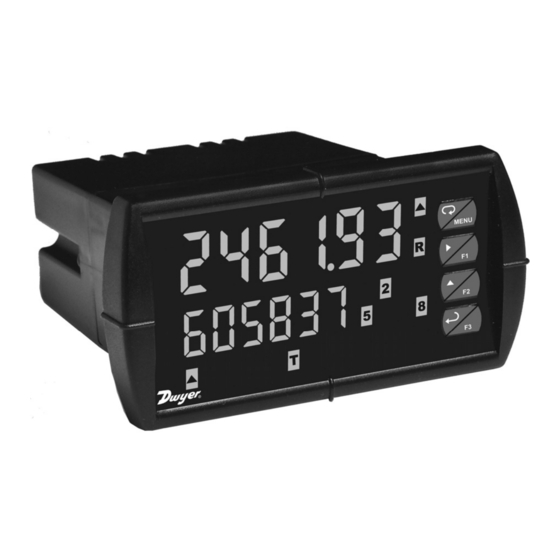
Dwyer Instruments Series APM Instruction Manual (108 pages)
Analog Panel Meter
Brand:
Dwyer Instruments
| Category:
Measuring Instruments
| Size: 1 MB
Table of Contents
Limited Warranty
2
Table of Contents
3
Introduction
7
Ordering Information
7
Specifications
8
General
8
Process Input
9
Rate/Totalizer
10
Relays
11
Isolated 4-20 Ma Transmitter Output
12
Modbus ® RTU Serial Communications
13
PMA-12 Digital Input & Output Expansion Module
13
Compliance Information
14
Safety
14
Electromagnetic Compatibility
14
Safety Information
15
Figure 1: 1/8 DIN Panel Cutout and Mounting
16
Installation
16
Unpacking
16
Panel Mounting Instructions
16
Figure 2: Meter Dimensions - Side View
17
Figure 3: Meter Dimensions - Top View
17
Figure 4: Jumper Configuration for 12/24 VDC Power
18
Configuration for 12 or 24 VDC Power Option
18
Figure 5: Transmitter Supply Voltage Selection
19
Connectors Labeling
20
Power Connections
20
Transmitter Supply Voltage Selection (P+, P-)
19
Connections
19
Figure 7: Power Connections
20
Figure 6: Connector Labeling for Fully Loaded APM
20
Figure 8: Transmitters Powered by Internal Supply
21
Figure 9: Transmitter Powered by Ext. Supply or Self-Powered
21
Figure 10: Voltage Input Connections
22
Figure 11: Relay Connections
22
Modbus ® RTU Serial Communications
22
Relay Connections
22
Figure 12: AC and DC Loads Protection
23
Figure 13: Low Voltage DC Loads Protection
23
Switching Inductive Loads
23
4-20 Ma Output Connections
24
Analog Output Transmitter Power Supply
24
Figure 14: 4-20 Ma Output Connections
24
External Relay & Digital I/O Connections
25
Figure 15: Expansion Modules & DIN Rail Mounting Kit
25
Figure 16: External Relays Module Connections
25
Interlock Relay Feature
26
Signal Connections
21
Figure 17: Digital I/O Module Connections
26
Figure 18. Interlock Connection
26
Setup and Programming
27
Front Panel Buttons and Status LED Indicators
28
Display Functions and Messages
29
Main Menu
33
Analog Panel Meter
34
Reset Menu (Reset)
34
Control Menu (Contrl)
34
Setting Numeric Values
34
Setting up the Rate/Totalizer Meter (Setup)
35
Setting the Input Signal (Input)
36
Setting the Totalizer Features (Total)
36
Dual-Scale for Level Application
37
Setting the Decimal Point (Dec Pt)
38
Programming the Rate/Totalizer (Prog)
39
Multi-Point Calibration & Scaling
40
Panel Meter Pro Software
40
Scaling the Meter (SCALE)
41
Time Base, Total Conversion Factor & Total Reset
43
Calibrating the Meter with External Source (Cal)
44
Setting the Display Parameter & Intensity (Dsplay)
45
Display Setup Menu
46
Character Set for Engineering Units Display (D Unit)
47
Setting the Relay Operation (Relay)
48
Relay Assignment (Assign)
49
Setting the Relay Action
50
Programming Set and Reset Points
51
Setting Fail-Safe Operation
51
Programming Time Delay
51
Relay Action for Loss of 4-20 Ma Input (Loop Break)
51
Relay and Alarm Operation Diagrams
52
High Alarm Operation (Set > Reset)
52
Low Alarm Operation (Set < Reset)
53
High Alarm with Fail-Safe Operation (Set > Reset)
54
Low Alarm with Fail-Safe Operation (Set < Reset)
55
Pump Alternation Control Operation
56
Rate Relay Sampling Operation
57
Total Relay Sampling Operation
57
Signal Loss or Loop Break Relay Operation
58
Time Delay Operation
59
Relay Operation Details
60
Overview
60
Relays Auto Initialization
60
Fail-Safe Operation
60
Front Panel Leds
61
Latching and Non-Latching Relay Operation
61
Non-Latching Relay (Auto)
62
Non-Latching Relay (A-Nman)
62
Latching Relay (Latch)
62
Analog Panel Meter
63
Acknowledging Relays
63
Figure 19: Acknowledge Relays W/Function Key or Digital Input
63
Latching Relay (Lt-Clr)
63
Pump Alternation Control Applications (Altern)
64
Setting up the Interlock Relay (Force On) Feature
67
Scaling the 4-20 Ma Analog Output (Aout)
68
Setting up the Password (Pass)
69
Protecting or Locking the Meter
69
Total Reset Password & Non-Resettable Total
70
Making Changes to a Password Protected Meter
71
Disabling Password Protection
71
Advanced Features Menu
72
Advanced Features Menu & Display Messages
73
Noise Filter (Filter)
76
Noise Filter Bypass (Bypass)
76
Modbus ® RTU Serial Communications (Serial)
77
Select Menu (Select)
78
Signal Input Conditioning (Functn)
78
Low-Flow Cutoff (Cutoff)
81
Analog Output Programming (Aoutpr)
81
Programmable Function Keys User Menu (User)
82
Tare (Tare)
83
Internal Source Calibration (ICAL)
83
Meter Copy Function (Copy)
86
Figure 20: Meter Copy Connection
86
Meter Operation
88
Front Panel Buttons Operation
88
Function Keys Operation
88
Maximum/Minimum Readings
89
Troubleshooting
90
Diagnostics Menu (Diag)
90
Determining Software Version
90
Reset Meter to Factory Defaults
91
Factory Defaults & User Settings
92
Troubleshooting Tips
96
Alphabetical List of Display Functions & Messages
97
Figure 21:1/8 DIN Panel Cutout Template
105
Advertisement
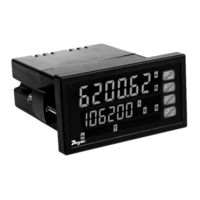
Dwyer Instruments Series APM Instruction Manual (92 pages)
Analog Panel Meter
Brand:
Dwyer Instruments
| Category:
Measuring Instruments
| Size: 3 MB
Table of Contents
Table of Contents
3
Introduction
7
Ordering Information
7
Specifications
8
General
8
Process Input
10
Rate/Totalizer
11
Relays
12
Isolated 4-20 Ma Transmitter Output
13
Modbus ® RTU Serial Communications
13
PMA-12 Digital Input & Output Expansion Module
14
Panel Meter Pro Software
14
Compliance Information
15
Safety
15
Electromagnetic Compatibility
15
Safety Information
16
Installation
17
Unpacking
17
Panel Mounting Instructions
17
Figure 1: 1/8 DIN Panel Cutout and Mounting
17
Mounting Dimensions
18
Figure 2: Meter Dimensions - Side View
18
Figure 3: Meter Dimensions - Top View
18
Transmitter Supply Voltage Selection (P+, P-)
19
Connections
19
Figure 4: Transmitter Supply Voltage Selection
19
Connectors Labeling
20
Power Connections
20
Figure 5: Connector Labeling for Fully Loaded APM
20
Figure 6: Power Connections
20
Signal Connections
21
Figure 7: Transmitter Powered by Internal Supply
21
Figure 8: Transmitter Powered by Ext. Supply or Self-Powered
21
Modbus RTU Serial Communications
22
Relay Connections
22
Figure 9: Voltage Input Connections
22
Figure 10: Relay Connections
22
Switching Inductive Loads
23
RC Networks Available from Dwyer Instruments, Inc
23
Figure 11: AC and DC Loads Protection
23
Figure 12: Low Voltage DC Loads Protection
23
F4 Digital Input Connections
24
4-20 Ma Output Connections
24
Analog Output Transmitter Power Supply
24
Figure 13: F4 Digital Input Connections
24
Figure 14: 4-20 Ma Output Connections
24
External Relay & Digital I/O Connections
25
Figure 15: Expansion Modules & DIN Rail Mounting Kit
25
Figure 16: External Relays Module Connections
25
Interlock Relay Feature
26
Figure 17: Digital I/O Module Connections
26
Figure 18. Interlock Connection
26
Setup and Programming
27
Panel Meter Pro Software
28
Panel Meter Pro Installation
28
Front Panel Buttons and Status LED Indicators
30
Display Functions and Messages
31
Main Menu
35
Setting Numeric Values
36
Setting up the Rate/Totalizer Meter (Setup)
37
Setting the Input Signal (Input)
38
Setting the Totalizer Features (Total)
38
Setting the Input Units or Custom Tags (Units)
39
Setting the Decimal Point (Dec Pt)
40
Programming the Rate/Totalizer (Prog)
40
Multi-Point Calibration & Scaling
41
Input Calibration Method (Incal)
41
Scaling the Meter (SCALE)
42
Calibrating the Meter with External Source (Cal)
43
Time Base, Total Conversion Factor & Total Reset
44
Setting the Display Parameter & Intensity (Dsplay)
45
Display Setup Menu
46
Setting the Relay Operation (Relay)
47
Relay Assignment (Assign)
48
Setting the Relay Action
49
Programming Set and Reset Points
50
Setting Fail-Safe Operation
50
Programming Time Delay
50
Relay Action for Loss of 4-20 Ma Input (Loop Break)
50
Relay and Alarm Operation Diagrams
51
High Alarm Operation (Set > Reset)
51
Low Alarm Operation (Set < Reset)
52
High Alarm with Fail-Safe Operation (Set > Reset)
53
Low Alarm with Fail-Safe Operation (Set < Reset)
54
Pump Alternation Control Operation
55
Rate Relay Sampling Operation
56
Total Relay Sampling Operation
56
Signal Loss or Loop Break Relay Operation
57
Time Delay Operation
58
Relay Operation Details
59
Overview
59
Relays Auto Initialization
59
Fail-Safe Operation
59
Front Panel Leds
60
Latching and Non-Latching Relay Operation
60
Non-Latching Relay (Auto)
61
Non-Latching Relay (A-Nman)
61
Latching Relay (Latch)
61
Latching Relay (Lt-Clr)
62
Acknowledging Relays
62
Figure 19: Acknowledge Relays W/Function Key or Digital Input
62
Pump Alternation Control Applications (Altern)
63
Setting up the Interlock Relay (Force On) Feature
66
Scaling the 4-20 Ma Analog Output (Aout)
67
Reset Menu (Reset)
68
Control Menu (Contrl)
68
Setting up the Password (Pass)
68
Protecting or Locking the Meter
69
Total Reset Password & Non-Resettable Total
69
Making Changes to a Password Protected Meter
70
Disabling Password Protection
70
Advanced Features Menu
71
Advanced Features Menu & Display Messages
71
Noise Filter (Filter)
74
Noise Filter Bypass (Bypass)
74
Rounding Feature (Round)
74
Modbus RTU Serial Communications (Serial)
75
Select Menu (Select)
76
Signal Input Conditioning (Functn)
76
Low-Flow Cutoff (Cutoff)
78
Totalizer Count Up/Down (Count)
78
Analog Output Programming (Aoutpr)
79
Programmable Function Keys User Menu (User)
80
Internal Source Calibration (ICAL)
81
Meter Operation
84
Front Panel Buttons Operation
84
Function Keys Operation
84
F4 Operation
85
Maximum/Minimum Readings
85
Troubleshooting
86
Diagnostics Menu (Diag)
86
Determining Software Version
86
Reset Meter to Factory Defaults
87
Factory Defaults & User Settings
88
Troubleshooting Tips
91
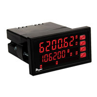
Dwyer Instruments Series APM Instruction Manual (45 pages)
Analog Panel Meter
Brand:
Dwyer Instruments
| Category:
Measuring Instruments
| Size: 2 MB
Table of Contents
Table of Contents
3
Introduction
6
Using the APM Like an MPM Process Meter
6
Ordering Information
6
Specifications
7
General
7
Process Input
8
Rate/Totalizer
8
Relays
9
Isolated 4-20 Ma Transmitter Output
9
USB Connection
10
On-Board Digital Input (F4)
10
Modbus ® RTU Serial Communications
10
Panel Meter Pro
10
Compliance Information
11
Safety
11
Electromagnetic Compatibility
11
Safety Information
11
Installation
11
Unpacking
11
Panel Mounting Instructions
12
Mounting Dimensions
12
Figure 1: 1/8 DIN Panel Cutout and Mounting
12
Figure 2. Meter Dimensions - Side View
12
Figure 3. Meter Dimensions - Top View
12
Installation Overview
13
Panel Meter Pro Software
13
Panel Meter Pro Installation
13
Transmitter Supply Voltage Selection (P+, P-)
14
Connections
14
Connectors Labeling
14
Figure 4: Transmitter Supply Voltage Selection
14
Figure 5. APM-100 & APM-200 Connectors Label
14
Figure 6. APM-120 & APM-220 Connectors Label
14
Figure 7. APM-101 & APM-201 Connectors Label
14
Figure 8. APM-140 & APM-240 Connectors Label
14
Figure 9. APM-121 & APM-221 Connectors Label
14
Figure 10. APM-141 & APM-241 Connectors Label
14
Power Connections
15
Signal Connections
15
Modbus RTU Serial Communications
15
Relay Connections
15
Figure 11: Power Connections
15
Figure 12: Transmitter Powered by Internal Supply
15
Figure 13: Transmitter Powered by External Supply or Self-Powered
15
Figure 14: Voltage Input Connections
15
Figure 15: Relay Connections
15
Switching Inductive Loads
16
F4 Digital Input Connections
16
4-20 Ma Output Connections
16
Analog Output Power Supply
16
Figure 16: AC and DC Loads Protection
16
Figure 17: Low Voltage DC Loads Protection
16
Figure 18: F4 Digital Input Connections
16
Figure 19: 4-20 Ma Output Connections
16
Figure 20. Analog Output Supply Powering Other Devices
16
External Relay & Digital I/O Connections
17
Interlock Relay Feature
17
Figure 21. Expansion Module & DIN Rail Mounting Kit
17
Figure 22. External Relays Module Connections
17
Figure 23. Digital I/O Module Connections
17
Figure 24. Interlock Connection
17
Setup and Programming
18
Front Panel Buttons and Status LED Indicators
18
Display Functions & Messages
19
Main Menu
21
Setting Numeric Values
21
Setting up the Rate/Totalizer Meter (Setup)
21
Setting the Input Signal (Input)
22
Setting the Totalizer Features (Total)
22
Setting the Display Units or Custom Tags (Units)
22
Setting the Decimal Point (Dec. P T)
23
Programming the Rate/Totalizer (Prog)
23
Setting the Display Parameter & Intensity (Dsplay)
25
Display Intensity (D-Inty)
25
Setting the Relay Operation (Relay)
26
Relay Assignment (Assign)
26
Setting the Relay Action
26
Programming Set and Reset Points
27
Setting Fail-Safe Operation
27
Programming Time Delay
27
Relay Action for Loss of 4-20 Ma Input (Loop Break)
27
Relay and Alarm Operation Diagrams
28
High Alarm Operation (Set > Reset)
28
Low Alarm Operation (Set < Reset)
28
High Alarm with Fail-Safe Operation (Set > Reset)
28
Low Alarm with Fail-Safe Operation (Set < Reset)
28
Time Delay Operation
29
Rate Relay Sampling Operation
29
Total Relay Sampling Operation
29
Relay Operation Details
30
Overview
30
Relays Auto Initialization
30
Fail-Safe Operation
30
Front Panel Leds
30
Latching and Non-Latching Relay Operation
30
Non-Latching Relay (Auto)
31
Non-Latching Relay with Manual Reset (A-Nman)
31
Latching Relay with Clear (Latch)
31
Latching Relay (Lt-Clr)
31
Acknowledging Relays
32
Setting up the Interlock Relay (Force On) Feature
32
Scaling the 4-20 Ma Analog Output (Aout)
33
Reset Menu (Reset)
33
Manual Control Menu (Contrl)
33
Setting up the Password (Pass)
34
Protecting or Locking the Meter
34
Total Reset Password & Non-Resettable Total
34
Making Changes to a Password Protected Meter
34
Disabling Password Protection
34
Advanced Features Menu
35
Advanced Features Menu & Display Messages
35
Noise Filter (Filter)
36
Noise Filter Bypass (Bypass)
36
Rounding Feature (Round)
36
Modbus RTU Serial Communications (Serial)
36
Select Menu (Select)
37
Input Signal Conditioning (Functn)
37
Low-Flow Cutoff (Cutoff)
38
Totalizer Count Up/Down (Count)
38
Analog Output Programming (Aoutpr)
38
Programmable Function Keys User Menu (User)
39
Internal Source Calibration (ICAL)
40
Meter Operation
41
Front Panel Buttons Operation
41
Function Keys Operation
41
F4 Operation
41
Maximum/Minimum Readings
41
Totalizer Overflow Displays Total to 9 Digits
41
Troubleshooting
42
Diagnostics Menu (Diag)
42
Determining Software Version
42
Reset Meter to Factory Defaults
42
Factory Defaults & User Settings
43
Troubleshooting Tips
44
Advertisement
Advertisement
Related Products
Dwyer Instruments SAH-22-IN
Dwyer Instruments SN Series
Dwyer Instruments SM Series
Dwyer Instruments SH Series
Dwyer Instruments SAH SMART Air Hood Series
Dwyer Instruments Smart Air Hood SAH Series
Dwyer Instruments SAH-22
Dwyer Instruments SAH-22HC
Dwyer Instruments 1207A
Dwyer Instruments Categories
Measuring Instruments
Transmitter
Switch
Controller
Thermometer
More Dwyer Instruments Manuals
Login
Sign In
OR
Sign in with Facebook
Sign in with Google
Upload manual
Upload from disk
Upload from URL