Table of Contents
Advertisement
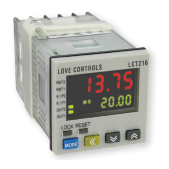
SERIES LCT216
DIGITAL TIMER/TACHOMETER/COUNTER
3 Controls in 1 Device, DIP Switch Configuration
The SERIES LCT216 Digital Timer/Tachometer/Counter combines a versatile timer,
counter, and tachometer all in one device. The bright, easy-to-read display shows the
desired set point and the current process value as well as the operating mode that the
control is functioning in. For quick set up, many of the programming parameters can
be set with external dip switches located on the side of the unit.
FEATURES/BENEFITS
• Fourteen pre-programmed timer functions
• One stage, two stage, batch, total, and dual counting modes
APPLICATIONS
• Industrial ovens
• Batch counting in conveyor systems
• Silk screening equipment
MODEL CHART
Model
Output Type
LCT216-100
Transistor
LCT216-110
Relay
1-7/8
[47.63]
1-7/8
[47.63]
SPECIFICATIONS
Operating Temperature Range: 32 to 122°F (0 to 50°C).
Humidity Conditions: 35 to 85% RH (non-condensing).
Control Output Ratings: (Out 1) Relay: SPST 5 A at 250 VAC; Transistor: NPN
open collector 100 mA / 30 VDC residual voltage = 1.5 VDC max; (Out 2) Relay:
SPST 5 A at 250 VAC, Transistor: NPN open collector 100 mA / 30 VDC residual
voltage = 1.5 VDC max.
Weight: 4 oz (114 g).
Reset Time: 0.001 s minimum.
Inputs: Dry contact, PNP, or NPN.
Timing Functions: 14 pre-programmed timing functions.
Supply Voltage: 100 to 240 VAC 50 / 60 Hz.
Power Consumption: Less than 10 VA.
Internal Power Supply: 12 VDC ±10%, 100 mA.
Display: Two-line 6 digit negative transmissive LCD display.
Agency Approvals: CE, cULus.
DIP SWITCH
3-23/64
[85.22]
3-1/8
[79.50]
1-3/4
[44.45]
Advertisement
Table of Contents

Subscribe to Our Youtube Channel
Related Manuals for Dwyer Instruments Love Controls LCT216 Series


Summary of Contents for Dwyer Instruments Love Controls LCT216 Series
- Page 1 SERIES LCT216 DIGITAL TIMER/TACHOMETER/COUNTER 3 Controls in 1 Device, DIP Switch Configuration DIP SWITCH 3-23/64 [85.22] 1-7/8 3-1/8 [47.63] [79.50] 1-7/8 1-3/4 [47.63] [44.45] The SERIES LCT216 Digital Timer/Tachometer/Counter combines a versatile timer, SPECIFICATIONS counter, and tachometer all in one device. The bright, easy-to-read display shows the Operating Temperature Range: 32 to 122°F (0 to 50°C).
- Page 2 Bulletin PC-LCT216 Series LCT216 Timer/Counter/Tachometer Specifications - Installation and Operating Instructions LOVE CONTROLS DIVISION Phone: 219/879-8000 www.love-controls.com Fax: 219/872-9057 e-mail:love@love-controls.com DWYER INSTRUMENTS INC. P.O. BOX 338 - MICHIGAN CITY, INDIANA 46360, U.S.A.
-
Page 3: Table Of Contents
TABLE OF CONTENTS Model Number Identification ..........3 Getting Started . -
Page 4: Model Number Identification
MODEL NUMBER IDENTIFICATION LCT216 Power Supply Output Type Communications 1 = 100 to 240 VAC 0 = Transistor 0 = None 1 = Relay GETTING STARTED Install the control as described on page 4. Wire your control following the instructions on page 5. Please read the Precautions section located at the end of this manual before wiring the control. -
Page 5: Mounting
MOUNTING METHOD Step 1: From the front of the panel, slide the controller housing through the cut out. The housing gasket should be against the housing flange before installing. Step 2: Slide the mounting collar over the housing from the rear of the panel. Step 3: Push the mounting collar forward until the bracket stops at the panel wall. -
Page 6: Wiring Diagrams
WIRING Terminal Identification CP2/ GATE OUT1 Multi-Function Input PIN RST2/ Timer & +12V RST1 START Counter Timer Tachometer Counter Gate Gate Reset1 Reset1 Reset1 Reset1 AC 100~240V Reset2 Start Start 50/60 Hz 5VA OUT2 Input Connections Page 5... -
Page 7: Front Panel Key Functions
FRONT KEY FUNCTIONS Key functions are as follows: MODE: Pressing the Mode key advances the display to the next menu item and saves any changed parameter values. UP ARROW: Increments a value or changes a menu item. If pressed while in the home display, the set point value will be increased. -
Page 8: Security Features
SECURITY FEATURES The Series LCT216 has two built-in security lock settings to prevent unauthorized personnel from changing parameter settings. The LoC1 setting affects all parameters in the controller. If LoC1 setting is enabled, the operator will have to unlock the controller to make any changes to the controller’s parameters The LoC2 setting affects all parameters except the set point and the reset function. -
Page 9: Timer Settings
TIMER SETTINGS The timer function of the series LCT216 takes a signal input to start a timing sequence. The sequence can be paused using the GATE input or reset using RST1 input. Use the below parameters and timing functions to configure the timer. Parameter Configuration FUnC timE... - Page 10 Timer Functions Page 9...
-
Page 11: Counter Settings
COUNTER SETTINGS Parameter configuration FUnC Cont Sets the controller to function as a counter CntFUn Select the counter to perform single stage counting, two stage counting, batch counting, total counting or dual counting. STAGE1 Controller has a single process value and set point value. Output 2 will be the same as output 1. - Page 12 Ud A Command up / down setting will increase or decrease the present value with each counter 1 input signal depending on if counter 2 input is engaged. When counter 2 input is engaged, each counter 1 input signal will decrease the count. Ud b Individual up / down setting will increase the present value with each counter 1 input signal and decrease with each counter 2 input...
- Page 13 C otmd Counter Output Mode determines the output operation of the control. It also determines how the counter will function after reaching the set point. See the output mode charts on page 13 for more information. C SPEd Counting Speed can be set from one count per second up to 10,000 counts per second.
-
Page 14: Counter Modes
Counter Output Mode Charts Input mode In put mo de Down U p/Down A, B, C Down Up/ Do wn A, B, C Outp ut Outpu t RE SET RESE T mode mode 9 99 9 99 999999 settin g settin g SV 2 S V2... -
Page 15: Tachometer Settings
TACHOMETER SETTINGS Parameter Configuration FUnC tACH Sets the controller to function as a tachometer. tAotmd Tachometer Output Mode determines the output condition when the process value exceeds the set point value. See output mode charts below for more information. C SPEd Maximum Input Frequency can be set from one count per second up to 10,000 counts per second. -
Page 16: Mixed Timer / Counter Settings
TIMER + COUNTER MIXED MODE SETTINGS Parameter Configuration FUnC Sets the controller to function as a timer and counter. T mode Timer Mode sets the timer to count up or Down. T otmd Timer Output Mode sets the output timing functions. See the timing functions section on page 9 for detail description of each timing function. -
Page 17: Dip Switch Settings
PuErS Power Save feature allows the control to save the current process value upon loss of power. SAvE Save process value upon power loss CLEAr Clear process value upon power loss rtSr Minimum width of reset signal determines how long the reset terminals must be engaged to reset the device. -
Page 18: Specifications
Displayed Unit 0.01 s 0.1 s min, 0.01 s min, 0.1 s 0.1 min hr, min, s Table C: Timer Units of Measure Output Mode Configuration Counter Timer Tachometer Signal ON Delay 1 Lo-Lo Signal ON Delay 2 Lo-Hi Signal OFF Delay Hi-Lo Signal ON Hi-Hi... -
Page 19: Precautions
DO NOT touch the internal wiring within this period. 12. Use dry cloth to clean the device. DO NOT use acid or alkaline liquid to clean the device. ©Copyright 2015 Dwyer Instruments, Inc Printed in U.S.A. 4/15 FR# 443702-00 Rev. 2 LOVE CONTROLS DIVISION Phone: 219/879-8000 www.love-controls.com...
Need help?
Do you have a question about the Love Controls LCT216 Series and is the answer not in the manual?
Questions and answers