
Related Manuals for Dwyer Instruments DFM


Summary of Contents for Dwyer Instruments DFM
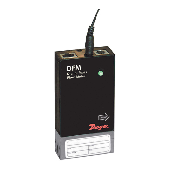
- Page 1 1/2/2020 Technical Data Sheet No. TD-DFM-0917 Date of Issue: OPERATING MANUAL Dwyer Instruments, Inc. DFM Digital Multi-Parameter Mass Flow Meter GlobalTestSupply www. .com uality Products Online at: sales@GlobalTestSupp...
- Page 2 Dwyer is a registered trademark of Dwyer Instruments, Inc. NOTE: Dwyer reserves the right to change designs and dimensions at its sole discretion at any time without notice. For certified dimensions, please contact Dwyer. GlobalTestSupply www. .com uality Products Online at:...
-
Page 3: Table Of Contents
TABLE OF CONTENTS Unpacking the DFM Mass Flow Meter........3 1.1 Inspect Package for External Damage........3 1.2 Unpack the Mass Flow Meter..........3 1.3 Returning Material for Repair..........3 2. Installation..................3 2.1 Safety Instructions..............3 2.2 Primary Gas Connections............4 3. Electrical Connections..............6 3.1 Power Supply Connections............7 3.2 Output Signals Connections..........7... - Page 4 6.4.13.4 Submenu “Modbus Interface” (optional)....52 6.4.13.5 Relay Assignment............54 6.4.13.6 Analog Output Configuration........54 6.4.13.7 Status LED Settings..........56 6.4.13.8 Signal Conditioner Settings........57 6.4.14 Sensor Zero Calibration..........57 6.4.14.1 DP Sensor Zero Calibration........58 6.4.14.2 Start AP Auto Tare...........59 6.4.15 Submenu “Alarms and Diagnostic”.......60 6.4.15.1 Alarm Event Register..........61 6.4.15.2 Diagnostic Events Register........65 6.4.15.3 Sensors ADC Reading (read only)......68 6.4.15.4 Temperature Sensors Diagnostic (read only)..69...
-
Page 5: Unpacking The Dfm Mass Flow Meter
UNPACKING THE DFM MASS FLOW METER Inspect Package for External Damage Your DFM Mass Flow Meter was carefully packed in a sturdy cardboard carton, with anti-static cushioning materials to withstand shipping shock. Upon receipt, inspect the package for possible external damage. If the unopened package is damaged, contact the shipping company immediately to make a report. -
Page 6: Primary Gas Connections
For more information, contact your distributor or Dwyer. The DFM Mass Flow Meter can be mounted in any position. It is not required to maintain straight runs of pipe upstream or downstream of the meter. It is preferable to install the meter in a stable environment, free of frequent and sudden temperature changes, high moisture, and drafts. - Page 7 Upstream particulate filters with maximum particulate size 20µ are recommended for all applications. DFM transducer ports are equipped with 10-32 female thread (DFM-02), 1/8" NPT female thread (DFM-03/05), and 1/4" NPT female thread (DFM-07). GlobalTestSupply www.
-
Page 8: Electrical Connections
ELECTRICAL CONNECTIONS DFM is equipped with an 8 pin-MiniDIN power, analog/relay output, communication interface connector. Table I explains the pin designations. See Figure 1 for a Pin Diagram. TABLE I: 8-PIN DESIGNATIONS AND NOTES FUNCTION NOTE Solid State SPST Relay NO... -
Page 9: Power Supply Connections
Power Supply Connections The AC to DC power supply requirements for DFM transducers are 9 to 26 Vdc, with maximum load current at least 100 mA (unipolar power supply), and maximum ripple below 150 mV P-P. -
Page 10: Digital Communication Interface Connections
DFM series Mass Flow Meters are equipped with calibrated 0-5Vdc, 0-10Vdc or 4-20 mA output signals. This linear output signal represents 0-100% of the flow meter’s full scale range. The user may select the desired analog interface type using a local OLED/Joystick interface or via digital communication interface. - Page 11 (pin 5 on the host PC DB9 connector)------pin 1 (Sleeve) of the 3-pin stereo jack connector Each DFM ordered with RS-232 interface option is supplied with default crossover 6-foot long communication cable (DWYER P/N: A-CBL-A232) DB9 female to stereo 3.5 mm Plug.
- Page 12 RS-485 GND (if available) .... pin 1 on 3-pin Audio-connector, the “sleeve” section DFM (GND), (Shield wire) Each DFM ordered with RS-485 interface option is supplied with a default 3- foot length of communication cable (DWYER P/N: A-CBL-A485) Stereo 3.5 mm plug to stripped wires.
- Page 13 DWYER FI I G G U U R RE 3: DFM R R S S -4 4 8 8 5 C C O O M M M M U U N N I I C CAT TI I O ON N...
-
Page 14: Principle Of Operation
See Tables X - XVIII which provide lists of supported gases. The DFM flow meter can display flow rate in 43 different mass flow or 15 different volumetric flow engineering units. Flow meter parameters and functions can be programmed locally via optional OLED/Joystick interface or remotely via the RS-232/RS-485 interface or optional Modbus RTU interface. - Page 15 INSTRUMENT WARM-UP TIME: < 5 seconds. MAXIMUM MEASURABLE FLOW RANGE: 133% F ull Scale. OPERATION RANGE/TURNDOWN RATIO: 0.5% t o 100% Full Scale / 200:1. MASS REFERENCE CONDITIONS (STP): 70°F & 14.696 PSIA (other references available on request). MAXIMUM INTERNAL GAS PRESSURE (STATIC): 120 PSIG. MAXIMUM INSTANTANEOUS DIFFERENTIAL PRESSURE ACROSS INLET AND OUTLET: 12 PSID.
-
Page 16: Full Scale
IN N L L E E T T A A N N D O O U U T T L L E E T T C C O ON NN NE EC C T T I I O O N N S S : : DFM-02 10-32 female thread, DFM-03/05 1/8"... - Page 17 CABLES Communication Cable for DFM with RS-232 Interface 6 FT CBL-A232 3.5mm stereo audio connector with 3-wire to 9-pin female D-connector (included with each DFM). Communication Cable for DFM with RS-485 Interface 6 FT CBL-A485 3.5mm stereo audio connector with 3-wire to stripped ends.
-
Page 18: Operating Instructions
WE E I I G G H H T SH H I I P P P P I I N N G W W E E I I G G H H T T DFM-01-DFM-20 flow meter 0.85 lbs. (0.4 kg) 2.55 lbs. -
Page 19: Swamping Condition
Temperature, Mass Flow, and Totalizer Volume readings in previously selected units of measure. NOTE: 5 seconds after the initial powering of the DFM flow meter, the status LED will emit a constant GREEN light (normal operation, ready to measure). 6. . 2 2... -
Page 20: Meter Process Information (Pi) Screens
6. . 3 3 M e e t t e e r P P r r o o c c e e s s s I I n n f f o o r r m m a a t t i i o o n ( ( P P I I ) ) s s c c r r ee e n n s Based on meter configuration, different parameters may be displayed in the Process Information (PI) screen by moving the control joystick (see Figure 6) Up or Down (DN). - Page 21 T: 2 2 6 6 8 8 3 3 5 2 2 4 4 . . 8 8 3 3 C C Temperature Sensor Reading (deg. C) Temperature Sensor Raw Counts FIGURE 7: DFM PROCESS INFORMATION SCREENS GlobalTestSupply www. .com uality Products Online at:...
-
Page 22: Local User Interface Menu Structure
6. . 4 4 L L o o c c a a l U U s s e e r r I I n n t t e e r r f f a a c c e M M e e n n u u S S t t r r u u c c t t u u r r e The diagram in Figure 12 (page 26) gives a general overview of the standard top-level display menu structure (when running firmware version A001). -
Page 23: Parameter Entry
NOTE: By default, the device is shipped from the factory with the Program Protection (PP) password set to Zero (PP Disabled). Once the correct password is entered, the Program Protection is turned off until the unit is powered up again. 6. -
Page 24: Submenu "Device Information
In order to protect device configuration parameters when changing the PP password, the old PP password must first be entered. Once old and new passwords are entered, the firmware will prompt with a confirmation message (see Figure 11) that the new password has been saved: Ne e w w P P P P P P a a s s s s w w o o r r d d ha a s s b b e e e e n n s s a a v v e e d PP P P a a s s s s w w o o r r d d i i s s C C h h a a n n g g e e d... - Page 25 TABLE VI: LIST OF SUPPORTED MASS FLOW UNITS OF MEASURE Number Mass Flow Rate Totalizer Volume Units Description Units STANDARD Percent of Full Scale SuL/min Microliters per minute SmL/sec Milliliter per second SmL/min Milliliters per minute SmL/hr Milliliter per hour SL/sec Liter per second SL/min...
- Page 26 TABLE VII: LIST OF SUPPORTED VOLUMETRIC FLOW UNITS OF MEASURE Number Flow Rate Units Totalizer Volume Units Description Percent of Full Scale uL/min Microliters per minute mL/sec Milliliter per second mL/min Milliliters per minute mL/hr Milliliter per hour L/sec Liter per second L/min Liter per minute L/hr...
-
Page 27: Submenu "User-Defined Units
NOTE: Program the Measuring Units first because subsequent menus may be based on the units selected. Once Flow Unit of Measure is changed, the Totalizer’s Unit of Measure will be automatically updated. 6. . 4 4 . . 5 5 “ “ S S u u b b m m e e n n u u U U s s e e r r - - D D e e f i f in n e e d U U n n i i t t s s ”... - Page 28 Figure 12 DFM Upper Levels Menu Structure GlobalTestSupply www. .com uality Products Online at: sales@GlobalTestSupp...
-
Page 29: Submenu "Select Gas
6. . 4 4 . . 6 6 S S u u b b m m e e n n u " " S S e e l l e e c c t G G a a s s " " The currently active gas can be selected by the user via OLED/joystick or digital communication interface. - Page 30 TABLE X: Standard Pure Non-Corrosive Gases A A l l l D D a a t t a a f f o o r S S ta a n n d d a a r r d d C C o o n n d d i i t t i i o o n n s s ( ( 7 7 0 ° ° F F a a n n d 1 1 4 4 . . 6 6 9 9 6 6 P P S S I I A A ) Ab b s s o o l l u u t t e Ga a s s Sh h o o r r t t...
- Page 31 TABLE XI: Bioreactor Gases A A l l l D D a a t t a a f f o o r S S t t a a n n d d a a r r d d C C o o n n d d i i t t i i o o n n s s ( ( 7 7 0 ° ° F F a a n n d 1 1 4 4 . . 6 6 9 9 6 6 P P S S I I A A ) Ab b s s o o l l u u t t e Ga a s s Sh h o o r r t t...
- Page 32 TABLE XII: Breathing Gases A A l l l D D a a t t a a f f o o r S S ta a n n d d a a r r d d C C o o n n d d i i t t i i o o n n s s ( ( 7 7 0 ° ° F F a a n n d 1 1 4 4 . . 6 6 9 9 6 6 P P S S I I A A ) Ab b s s o o l l u u t t e Ga a s s Sh h o o r r t t...
- Page 33 T T ABLE XIV: Fuel Gases A A l l l D D a a t t a a f f o o r S S ta a n n d d a a r r d d C C o o n n d d i i t t i i o o n n s s ( ( 7 7 0 ° ° F F a a n n d 1 1 4 4 . . 6 6 9 9 6 6 P P S S I I A A ) Ab b s s o o l l u u t t e Sh h o o r r t t De e n n s s i i t t y y g / l...
- Page 34 TABLE XV: Laser Gases A A l l l D D a a t t a a f f o o r S S t t a a n n d d a a r r d d C C o o n n d d i i t t i i o o n n s s ( ( 7 7 0 ° ° F F a a n n d 1 1 4 4 . . 6 6 9 9 6 6 P P S S I I A A ) Ab b s s o o l l u u t t e Ga a s s Sh h o o r r t t...
-
Page 35: 6.4.7 Submenu "User-Defined Mixture
TABLE XVIII: Welding Gases A A l l l D D a a t t a a f f o o r S S t t a a n n d d a a r r d d C C o o n n d d i i t t i i o o n n s s ( ( 7 7 0 ° ° F F a a n n d 1 1 4 4 . . 6 6 9 9 6 6 P P S S I I A A ) Ab b s s o o l l u u t t e Ga a s s Sh h o o r r t t... - Page 36 En n t t e e r r M M i i x x t t u u r r e N N a a m m e e : _ M _ yM _ _ i _ x 1 _ _ ...
- Page 37 MyMix1 G:0 Tot: 0.00% G1 Ar 0.00% 0.00% 0.00% 0.00% 0.00% Save, Esc to Exit Figure 18: G1 Component with Selected Gas Once the gas is selected for component G1, the screen shown in Figure 18 will appear. To select the ratio for component G1, press Right. The screen shown in the top of Figure 19 will appear.
- Page 38 MyMix1 G:0 Tot: 22.00% MyMix1 G:0 Tot: 10.00% G1 Ar 10.00% G1 Ar 10.00% 0.00% G2 He 12.00% 0.00% 0.00% 0.00% 0.00% 0.00% 0.00% Save, Esc to Exit Save, Esc to Exit MyMix1 G:0 Tot:100.0% MyMix1 G:0 Tot: 10.00% G1 Ar 10.00% G1 Ar...
-
Page 39: Submenu "Gas Flow Alarm
6. . 4 4 . . 8 8 S S u ub bm me en n u “ “ G G a a s s F F l l o o w w A A l l a a r rm m” ” The DFM provides the user with a flexible Alarm warning system that monitors the Fluid Flow for all conditions that fall outside configurable limits, as well as visual feedback for the user via the OLED, status LED or an SSR output. - Page 40 The following settings are available for the Flow Alarm (see Figure 12): a) Flow Alarm Mode (Tabular entry) This function determines whether the Flow Alarm is Enabled or Disabled, the only two selections available. The default entry is Disabled. Alarm Mode selections can be set with the joystick UP and DN buttons, and are accepted by pressing the joystick equivalent of the ENT button.
-
Page 41: 6.4.9 Submenu "Gas Pressure Alarm
6.4.9 Submenu “Gas Pressure Alarm” The DFM provides the user with a flexible Alarm system that monitors the Fluid Pressure for conditions that fall outside configurable limits and provides visual feedback for the user via the OLED, status LED or an SSR output. The Pressure Alarm has several attributes which may be configured by the user via the OLED/joystick interface or digital communication interface. - Page 42 b) Low Pressure Alarm (Numerical entry) The limit of required Low Pressure Alarm value can be entered in currently selected pressure units, in increments of 0.1% of the pressure full scale range from 0.0 to 99.9%. If a Low Alarm occurs, and SSR output is assigned to the Low Pressure Alarm event (see Section 6.4.13.5) the SSR output will be activated when the pressure is less than the Low Pressure Alarm value.
-
Page 43: Submenu "Gas Temperature Alarm
A A l l a a r rm m" " The DFM provides the user with a flexible Alarm system that monitors the Fluid Temperature for conditions that fall outside configurable limits and provides visual feedback for the user via the OLED, status LED or an SSR output. - Page 44 The Low Temperature Alarm condition is also indicated on the corresponding Process Information Screen by alternating every second between units of measure and the “L” alert, meaning Low. NOTE: The value of the Low Pressure Alarm must be less than the value of the High Pressure Alarm.
-
Page 45: Totalizers Settings
6. . 4 4 . . 1 1 1 To o t t a al li i z z e e r r s S S e e t t t ti i n n g g s s The DFM provides the user with two independent Programmable Flow Totalizers. - Page 46 is not required, set “Totalizer Action Volume” value to zero; this is the default setting. d) Totalizer Power On Delay (Numerical entry) Sometimes it is convenient to start the Totalizer only after a specified power-up delay interval. Mass flow meters require some warm-up time from the power-up event in order to stabilize the process variable output and to get an accurate reading.
-
Page 47: Submenu "Pulse Output
Figure 25: Totalizer Reset Confirmation A local maintenance push button is available to manually reset the Totalizer in the field for DFM meters without the OLED/joystick option. The maintenance push button is located on the left side of the flow meter (see Section 6.5 “Multi-Functional Push-Button Operation”). -
Page 48: General Settings
(SSR) output must be assigned to the “Pulse Output” function (see Section 6.4.13.5). The Pulse output signal will be accessible via SSR output (pins 1 and 2) on the DFM 8-pin MiniDIN connector (see Figure 1 for proper wiring connections). -
Page 49: Display And Process Information (Pi) Screens
St t a a n n d d a a r r d Te e m m p p e e r r a a t t u u r r e e St t a a n n d d a a r r d P P r r e e s s s s u u r r e e No o r r m m a a l Te e m m p p e e r r a a t t u u r r e e No o r r m m a a l P P r r e e s s s s u u r r e e Standard Temperature and Normal Temperature menu selections allow the... - Page 50 Th h e e f f o o l l l l o o w w i i n n g s s e e t t t t i i n n g g s s a a r r e a a v v a a i i l l a a b b l l e f f o o r O O L L E E D D D D i i s s p p l l a a y y : : a) D D i i s s p p l l a a y M M o o d d e e This option determines whether the display screens are in static (manual control) or dynamic (automatic sequencing) mode.
- Page 51 NOTE: By default, the brightness level is set to 127 which is the optimal level for room temperature (20 °C or 70 °F). e) OLED Screensaver Mode OLED is subject to burn-in. It can retain images on the screen temporarily and, in some cases even permanently if it is left static for too long.
-
Page 52: Submenu "Communication Port Settings
Screensaver mode to "OLED Off". h) Flow Rate Precision (Tabular entry) The DFM Flow Meter calculates Flow Rate Precision automatically, based on selected units of measure and current gas full scale flow rate to keep the reading. By default, the Flow Rate Precision is set to “Normal”. In cases where more digits after the decimal point are required, the user can change decimal point precision to the “Elevated”... - Page 53 By default, the device is shipped from the factory with its baud rate set to 9600. NOTE: The baud rate set on the DFM meter should always match the baud rate of the host PC and/or PLC that it is connected to. c) RS-485 Bus Address (Numerical entry) The RS-232 interface does not require bus addressing.
-
Page 54: Submenu "Modbus Interface" (Optional)
Line Termination (LT) near each of the two ends of the RS-485 bus. If you are connecting a DFM meter as the last device in the end of a long (more than 100 meters) transmission line, you can use this menu selection to internally connect a 120Ω... - Page 55 9 9 6 6 0 0 0 0 1 1 9 9 2 2 0 0 0 3 3 8 8 4 4 0 0 0 5 5 7 7 6 6 0 0 0 1 1 1 1 5 5 2 2 0 0 0 0 By default, the device is shipped from the factory with its baud rate set at 9600.
-
Page 56: Relay Assignment
Ou ut tp p u u t t C C o on nf i f ig g u u r r a at ti io o n The DFM series Mass Flow Meters are equipped with calibrated 0-5Vdc, 0-10Vdc, and 4-20 mA output signals. The following options are provided... - Page 57 EEPROM will void the calibration warranty supplied with the instrument. Power up the DFM meter for at least 30 minutes prior to commencing the calibration procedure. Observe the current analog output mode settings. For 0-5 or 0-10 Vdc output calibration: Connect the corresponding type of measurement device (voltmeter) to pins 6 (plus) and 4 (minus) of the 8-pin MiniDIN connector.
-
Page 58: Status Led Settings
6. . 4 4 . . 1 1 3 3 . . 7 S S t t a at tu us s L L E E D S S e e t t t ti in n g g s s DFM series Mass Flow Meters are equipped with dual color LED which allows signaling a variety of different events with combinations of three colors (red, green and amber) and a specific time pattern. -
Page 59: Signal Conditioner Settings
6. . 4 4 . . 1 1 4 S S e e n n s s o or r Z Z e e r r o o C C a a l l i i b b r r a at ti io o n The DFM includes an auto zero function that, when activated, automatically adjusts the differential pressure sensors to read zero. -
Page 60: Dp Sensor Zero Calibration
Shut off the gas flow into the DFM meter. To ensure that no seepage or leaking occurs into the meter, it is good practice to temporarily disconnect the gas source. The Auto Zero may be initiated locally using optional OLED/... -
Page 61: Start Ap Auto Tare
6. . 4 4 . . 1 1 4 4 . . 2 S S t t a ar rt A A P P A A u u t t o o Ta a r re The DFM instrument is equipped with a high accuracy, high resolution absolute pressure sensor which was calibrated at the factory and does not require additional calibration. -
Page 62: Submenu "Alarms And Diagnostic
D D i i a a g g n n o o s st ti i c c ” The DFM is equipped with Alarm and Diagnostics Events registers. These are available via digital interface and an optional OLED screen indication. The Alarm Event Register monitors non-critical alarm events related to the meter settings and process variables. -
Page 63: Alarm Event Register
6. . 4 4 . . 1 1 5 5 . . 1 A A l l a a r r m E E v v e e n n t R R e e g g i i s s t t e e r r Th h e e f f o o l l l l o o w w i i n n g a a l l a a r r m e e v v e e n n t t s s a a r r e s s u u p p p p o o r r t t e e d d : : TABLE XIX: ALARM EVENTS REGISTER EVENT NUMBER... - Page 64 Al l r r m m E E v v e e n n t t s S S t t a a t t u u s s : 0 No A A c c t t i i v v e e A A l l a a r r m m s s Figure 32: Alarm Events Register (with no alarms) A typical display with two active Alarm Events is shown in Figure 33: Al l r r m m E E v v e e n n t t s S S t t a a t t u u s s : 2...
- Page 65 A A l l a a r r m E E v v e e n n t t s s M M a a s s k k R R e e g g : : 2 - R R a a n n g g e b b / / w H H - - L [ [ * * ] 3 - To o t t # # 1 1 >...
- Page 66 To disable a latch feature, the corresponding asterisk must be removed. Use the ENT button to accept and save new Latch Alarm Event Register settings in the meter’s nonvolatile memory. d) Reset Status Alarm Event Register (Tabular entry) The Status Alarm Event Register can be reset by selecting the “Reset Alarm Event Reg”menu option.
-
Page 67: Diagnostic Events Register
6. . 4 4 . . 1 1 5 5 . . 2 D D i i a a g g n n o o s s t t i i c c E E v v e e n n t t s s R R e e g g i i s s t t e e r r Th h e e f f o o l l l l o o w w i i n n g a a l l a a r r m e e v v e e n n t t s s a a r r e s s u u p p p p o o r r t t e e d d : : TABLE XX: DIAGNOSTIC EVENTS REGISTER EVENT NUMBER... - Page 68 Di i a a g g E E v v e e n n t t s S S t t a a t t u u s s : 0 No A A c c t t i i v v e e E E v v e e n n t t s s Figure 38: Diagnostic Events Status Register (no active events) A typical display with two active Diagnostic events is shown below: Di i a a g g E E v v e e n n t t s S S t t a a t t u u s s : 2...
- Page 69 In the example shown above, latch features for all events except #0 are disabled. In order to change Mask Diagnostic Event Register settings, the user houls select the desired event with the joystick UP and DN buttons, then press the RIGHT button. The asterisk will appear in or disappear from the brackets to the right of the selected event.
-
Page 70: Sensors Adc Reading (Read Only)
Reset DiagEvents Reg.: DO YOU WANT RESET EVENT REG? Figure 42: Resetting Diagnostic Events Register When you select the “YES” option, the Event Register will be reset and the following confirmation screen will appear: *********************** Event Reg. Has been reset! *********************** Press any Key... -
Page 71: Temperature Sensors Diagnostic (Read Only)
6. . 4 4 . . 1 1 5 5 . . 4 Te e m m p p e e r r a a t t u u r r e e S S e e n n s s o o r r s D D i i a a g g n n o o s s t t i i c c ( ( r r e e a a d o o n n l l y y ) This menu selection provides raw or average (filtered) ADC counts for gas temperature and pressure sensor temperature readings, which may be useful for Digital Signal Processing (DSP) troubleshooting (read only). -
Page 72: Analog Output & Po Queue Diagnostic (Read Only).70 6.4.15.6 Reference Voltage & Dsp Calculation Diagnostic
Reference Voltage and DSP Calculation troubleshooting. 6.5 Multi-Functional Push-Button Operation The DFM provides the user with a micro push-button switch accessible via a small hole on the right side of the instrument (see Figure 48), which can be used to select/start some important actions for the instrument. The micro push-button switch functionality is available on all DFM models in both analog and digital operation mode. - Page 73 FIGURE 48: DFM INTERFACE CONNECTORS AND MULTI-FUNCTION PUSH-BUTTON ACCESS HOLE See Table XXI on the following page for explanations. GlobalTestSupply www. .com uality Products Online at: sales@GlobalTestSupp...
-
Page 74: Status Led Indication
TABLE XXI: LED Indications using the Multi-Function Push-Button During Normal Running Mode STATUS LED TIME INSTRUMENT ACTION INDICATION PUSHED Amber flashing On/Off Pressing a switch briefly (<6 sec) will not cause every 2 seconds seconds unwanted actions from the device but will Com. -
Page 75: Maintenance
7. . 1 1 G G e e n n e e r r a al It is important that be DFM Mass Flow Meter be used only with clean, dry, non-corrosive filtered gases. Liquids may not be metered. Since the restrictor flow element (RFE) consists of small stainless steel channels, it is prone to occlusion due to impediments of large particles or gas crystallization. -
Page 76: Recalibration
8 RECALIBRATION The recommended period for recalibration of the DFM flow meter is once annually. Dwyer Instruments’ Flow Calibration Laboratory offers professional calibration support for Mass Flow Meters using NIST-traceable precision calibrators under strictly controlled conditions. NIST-traceable calibrations are available. - Page 77 RS-232 option. Several examples of commands are shown below. All assume that the DFM meter has been configured for decimal address 18 (12 hex) on the RS-485 bus: 1.
- Page 78 NOTE: Do not assign the same RS-485 address to two or more devices on the same RS-485 bus. If two or more devices with the same address are connected to one RS-485 network, a communication collision on the bus will result, leading to communication errors.
- Page 79 Dwyer TABLE XXII: DFM ASCII SOFTWARE INTERFACE COMMANDS Note: An “*” indicates power up default settings. An “**”indicates optional feature not available on all models. GlobalTestSupply www. .com uality Products Online at: sales@GlobalTestSupp...
- Page 80 GlobalTestSupply www. .com uality Products Online at: sales@GlobalTestSupp...
- Page 81 GlobalTestSupply www. .com uality Products Online at: sales@GlobalTestSupp...
- Page 82 GlobalTestSupply www. .com uality Products Online at: sales@GlobalTestSupp...
- Page 83 GlobalTestSupply www. .com uality Products Online at: sales@GlobalTestSupp...
- Page 84 GlobalTestSupply www. .com uality Products Online at: sales@GlobalTestSupp...
- Page 85 GlobalTestSupply www. .com uality Products Online at: sales@GlobalTestSupp...
- Page 86 GlobalTestSupply www. .com uality Products Online at: sales@GlobalTestSupp...
- Page 87 GlobalTestSupply www. .com uality Products Online at: sales@GlobalTestSupp...
- Page 88 GlobalTestSupply www. .com uality Products Online at: sales@GlobalTestSupp...
- Page 89 GlobalTestSupply www. .com uality Products Online at: sales@GlobalTestSupp...
- Page 90 GlobalTestSupply www. .com uality Products Online at: sales@GlobalTestSupp...
- Page 91 GlobalTestSupply www. .com uality Products Online at: sales@GlobalTestSupp...
- Page 92 GlobalTestSupply www. .com uality Products Online at: sales@GlobalTestSupp...
- Page 93 GlobalTestSupply www. .com uality Products Online at: sales@GlobalTestSupp...
- Page 94 GlobalTestSupply www. .com uality Products Online at: sales@GlobalTestSupp...
- Page 95 GlobalTestSupply www. .com uality Products Online at: sales@GlobalTestSupp...
- Page 96 GlobalTestSupply www. .com uality Products Online at: sales@GlobalTestSupp...
- Page 97 GlobalTestSupply www. .com uality Products Online at: sales@GlobalTestSupp...
- Page 98 GlobalTestSupply www. .com uality Products Online at: sales@GlobalTestSupp...
- Page 99 UART Error Codes: 1 – Command Not Supported or Back Door is not enabled. 2 – Wrong# of Arguments 3 – Address is Out of Range (MR or MW commands) 4 – Wrong# of the characters in the Argument 5 – Attempt to alter Write-Protected Area in the EEPROM 6 –...
-
Page 100: Troubleshooting
10 0 . . 1 C C o om mm mo on n C C o on nd d i i t t i i o o n n s s Your DFM Mass Flow Meter was thoroughly checked at numerous quality control points during and after manufacturing and assembly operations. - Page 101 NO. INDICATION LIKELY REASON SOLUTION OLED Display reading Output 0-5Vdc Return DFM to factory for repair. does correspond to the schematic is burned correct flow range, but out or damaged. 0-5Vdc output signal Analog flow output Restore original EEPROM scale...
- Page 102 The Status LED Fatal Error (EEPROM or Cycle the power on the DFM. If indicator is Auto Zero error). Status LED still constantly on constantly on with with RED light, wait 1 minute the RED light.
-
Page 103: Technical Assistance
10 0 . . 3 Te e c c h h n ni ic c a al l A A s s s si is s t t a an nc c e e Dwyer Instruments will provide technical assistance over the phone to qualified repair personnel. -
Page 104: Appendix I: Component Diagram
AP P P P E E ND D I I X I: CO O M M P P O O N N E E N N T T D D I I A A G G R R A A M TO O P P C C O O M M P P O O N N E E N N T S S I I D D E E GlobalTestSupply www. - Page 105 BO O T T T T O O M C C O O M M P P O O N N E E N N T S S I I D D E E GlobalTestSupply www. .com uality Products Online at: sales@GlobalTestSupp...
-
Page 106: Appendix Ii: Dimensional Drawings
ND D I I X X I II I : DI I M M E E N N S S I I O O N N A A L L D D R R AW W I I N N G G S DFM-01-DFM-20 1.266... - Page 107 DFM-21-DFM-56 1.266 (32.2 mm) 4.401 (111.8 mm) 0.525 (13.3 mm) 0.335 � (8.5 mm) 10-32 UNF - 2B 0.200 2.376 0.525 (2) ports (60.4 mm) (13.35 mm) 1.050 (26.7 mm) 0.800 (20.3 mm) � 6-32 UNC - 2B 0.220 (2) holes 1.846...
-
Page 108: Appendix Iii: Warranty
AP P P P E E ND D I I X I I I I I: WARRANTY (Be sure to follow Return Procedures as outlined in Section 1.3) WARRANTY Refer to “Terms and Conditions of Sale” in our catalog and on our website. -
Page 109: Appendix Iv: Index Of Figures
APPENDIX IV: INDEX OF FIGURES Figure # Title Page DFM 8-pin Mini-DIN Connector Configuration DFM RS-232 Communication Interface Connections DFM RS-485 Communication Interface Connections DFM Firmware and Communication Interface Information Screen DFM Initial Process Information Joystick DFM Process Information Screens... - Page 110 Confirmation of Diagnostic Events Register Reset Pressure Sensors ADC Diagnostic Temperature Sensors Diagnostics Analog Output and PO Queue Diagnostic Reference Voltage and DSP Calculation Diagnostic DFM Interface Connectors and Multi- Function Push-Buston Access Hole GlobalTestSupply www. .com uality Products Online at:...
-
Page 111: Appendix V: Index Of Tables
Concentrator Gases XVII Stack Gases XVIII Welding Gases Alarm Events Register Diagnostic Events Register LED Indications using the Multi-Function Push- Button During Normal Running Mode Dwyer DFM ASCII Software Interface XXII 77-96 Commands XXIII Troubleshooting Guide 98-100 GlobalTestSupply www. .com...
Need help?
Do you have a question about the DFM and is the answer not in the manual?
Questions and answers