Advertisement
Available languages
Available languages
Dwyer Mark II Manometers come in a vari-
ety of ranges. Make sure the oil being used
is for the correct manometer.
Mark II #25, 27, MM-80 and M-700 Pa use
red gage oil (specific gravity 0.826).
Mark II #26, 28 and MM180 use blue gage
oil (specific gravity 1.9).
If additional oil is required, call or fax nearest
Dwyer office listed at bottom of page.
INSTALLATION
Position manometer on a vertical surface.
Drill two 1/8˝ or 9/64˝ holes on a vertical line
315/16˝ apart. Loosely mount manometer
with self-tapping screws provided. Adjust
gage until level bubble is centered in level
vial, then secure the manometer tightly.
For portable use, order optional A-612
Portable Stand.
DWYER INSTRUMENTS, INC.
P.O. BOX 373 • MICHIGAN CITY, INDIANA 46361, U.S.A.
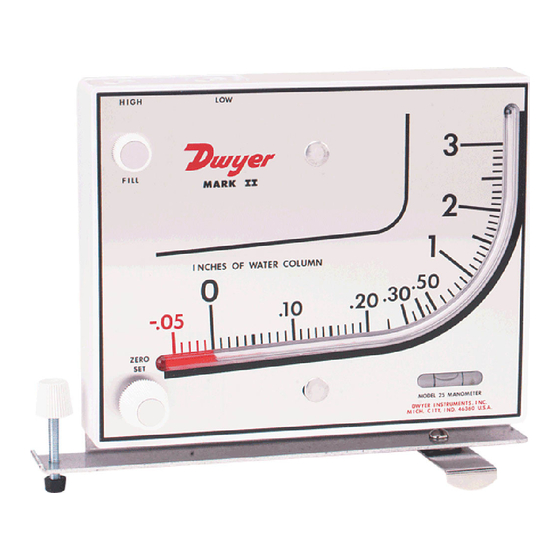
Mark II Series Molded Plastic Manometers
Specifications - Instructions and Operation
Mark II Model No. 25
inclined-vertical manometer,
(shown with optional A-612 portable stand)
FILLING
Turn the zero set knob counterclockwise until
it stops, then turn clockwise 3 full turns. This
puts zero in approximately the middle of the
travel adjustment in either direction. Remove
the fill plug and fill with gage fluid until fluid
reaches zero on scale. Minor adjustments
can be made to adjust zero by adjusting zero
knob. Replace fill plug. If gage is overfilled,
remove excess by inserting pipe cleaner
through the fill port to blot up excess oil.
MAINTENANCE
Check oil level regularly and adjust zero with
zero adjust knob. Be sure tubing connec-
tions are disconnected and gage is open to
atmosphere before adjusting zero.
Clean with mild soap and water. Avoid any
cleaning fluids which may result in damaging
the gage.
ACCESSORIES
Each Mark II manometer includes two tubing
connectors for 1/8˝ pipe or sheet metal
ducts, two mounting screws, 3/4 oz. bottle
of indicating fluid, red and green pointer
flags, 8´ of double column tubing and instruc-
tions.
Phone: 219/879-8000
Fax: 219/872-9057
Bulletin D-58
www.dwyer-inst.com
e-mail: info@dwyer-inst.com
Advertisement
Table of Contents

Related Manuals for Dwyer Instruments 25


Summary of Contents for Dwyer Instruments 25
- Page 1 3 full turns. This puts zero in approximately the middle of the Mark II #25, 27, MM-80 and M-700 Pa use travel adjustment in either direction. Remove red gage oil (specific gravity 0.826).
- Page 2 Flow in cu. ft. per min. = Duct area in square 0.9. feet x air velocity in ft. per min. Printed in U.S.A. 1/04 FR# 67-440215-00 Rev. 11 ©Copyright 2004 Dwyer Instruments, Inc. DWYER INSTRUMENTS, INC. Phone: 219/879-8000 www.dwyer-inst.com P.O. BOX 373 • MICHIGAN CITY, INDIANA 46361, U.S.A.
- Page 3 Instale el Mark II en una superficie vertical de peso específico 0,826 para los mod- adecuada. El ambiente debe estar libre de elos 25; 27; MM-80 y M-700Pa. Use vapores de sustancias cloradas, o solventes solamente aceite azul de peso específi- tales como benceno, acetona, tetracloruro co 1,9 para los modelos 26;...
- Page 4 (roja y verde)y adhiéralas (pie ) X Veloc. de aire (pie/min.) adyacentes al tubo indicador para marcar FR# 67-440215-00 Rev. 11 ©Copyright 2004 Dwyer Instruments, Inc. Printed in U.S.A. 1/04 DWYER INSTRUMENTS, INC. Phone: 219/879-8000 www.dwyer-inst.com P.O. BOX 373 • MICHIGAN CITY, INDIANA 46361, U.S.A.
Need help?
Do you have a question about the 25 and is the answer not in the manual?
Questions and answers