Table of Contents
Advertisement
Quick Links
0-20 mA, 4-20 mA, 0-5 V, 1-5 V, ±10 V Inputs
•
NEMA 4X, IP65 Front
•
Input Power Options Include 85-265 VAC or 12-24 VDC
•
Large Dual-Line 6-Digit Display, 0.60" & 0.46"
•
Sunlight Readable Display Models
•
Isolated 24 VDC Transmitter Power Supply
•
Signal Input Conditioning for Flow
•
Programmable Displays & Function Keys
•
Rate Displayed as Units per Second, Minute, Hour, or Day
•
Total, Grand Total or Non-Resettable Grand Total
•
9-Digit Totalizer with Total Overflow Feature
•
32-Point Linearization, Square Root or Exponential Linearization
•
Multi-Pump Alternation Control
•
2 or 4 Relays + Isolated 4-20 mA Output for Rate/Total/Grand Total
•
External 4-Relay & Digital I/O Expansion Modules
•
RS-232 & RS-485 Serial Communication Options
•
Modbus
®
RTU Communication Protocol Standard
•
Free USB Programming Software & Cable
•
DWYER INSTRUMENTS, INC.
PO Box 373 • Michigan City IN 46360 USA
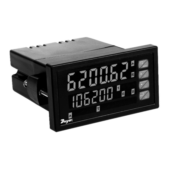
Series APM Analog Panel Meter
Instruction Manual
Bulletin: L-APM
Phone: (800) 872-9141
Fax: (219) 872-9057
www.dwyer-inst.com
Advertisement
Table of Contents

Subscribe to Our Youtube Channel
Related Manuals for Dwyer Instruments APM-100


Summary of Contents for Dwyer Instruments APM-100
- Page 1 RS-232 & RS-485 Serial Communication Options • Modbus ® RTU Communication Protocol Standard • Free USB Programming Software & Cable • DWYER INSTRUMENTS, INC. Phone: (800) 872-9141 Fax: (219) 872-9057 PO Box 373 • Michigan City IN 46360 USA www.dwyer-inst.com...
- Page 2 Anyone using this product for such applications does so at his/her own risk. Dwyer Instruments, Inc. shall not be held liable for damages resulting from such improper use. Limited Warranty Dwyer Instruments, Inc.
-
Page 3: Table Of Contents
Modbus RTU Serial Communications ----------------------------------- 22 Relay Connections ----------------------------------------------------------- 22 Switching Inductive Loads -------------------------------------------------- 23 RC Networks Available from Dwyer Instruments, Inc. ----------- 23 F4 Digital Input Connections ----------------------------------------------- 24 4-20 mA Output Connections ---------------------------------------------- 24 Analog Output Transmitter Power Supply ------------------------------ 24 External Relay &... - Page 4 Analog Panel Meter Instruction Manual Main Menu ------------------------------------------------------------------------ 35 Setting Numeric Values ------------------------------------------------------ 36 Setting Up the Rate/Totalizer Meter (setup) --------------------------- 37 Setting the Input Signal (Input) ------------------------------------------ 38 Setting the Totalizer Features (total) ---------------------------------- 38 Setting the Input Units or Custom Tags (units)---------------------- 39 Setting the Decimal Point (dEc pt) -------------------------------------- 40 Programming the Rate/Totalizer (prog) -------------------------------- 40 Multi-Point Calibration &...
- Page 5 Analog Panel Meter Instruction Manual Pump Alternation Control Applications (Altern) --------------------- 63 Setting Up the Interlock Relay (Force On) Feature ------------------ 66 Scaling the 4-20 mA Analog Output (Aout) ---------------------------- 67 Reset Menu (reset) ------------------------------------------------------------ 68 Control Menu (Contrl) -------------------------------------------------------- 68 Setting Up the Password (pass) ------------------------------------------- 68 Protecting or Locking the Meter ------------------------------------------- 69 Total Reset Password &...
- Page 6 Analog Panel Meter Instruction Manual Table of Figures Figure 1: 1/8 DIN Panel Cutout and Mounting ........17 Figure 2: Meter Dimensions - Side View ..........18 Figure 3: Meter Dimensions - Top View ..........18 Figure 4: Transmitter Supply Voltage Selection ....... 19 Figure 5: Connector Labeling for Fully Loaded APM .......
-
Page 7: Introduction
4-20 mA isolated output, Modbus RTU serial communications, and digital I/O options make the APM an excellent addition to any system. ORDERING INFORMATION 85-265 VAC 12-24 VDC Options Installed Model Model APM-100 APM-200 No options APM-101 APM-201 4-20 mA output APM-120 APM-220... -
Page 8: Specifications
Analog Panel Meter Instruction Manual SPECIFICATIONS Except where noted all specifications apply to operation at +25°C. General DISPLAY Upper display: 0.6" (15 mm) high, red LEDs Second display: 0.46" (12 mm) high, red LEDs 6 digits: each (-99999 to 999999), with lead zero blanking. DISPLAY Eight user selectable intensity levels INTENSITY... - Page 9 Analog Panel Meter Instruction Manual FUSE Required external fuse: UL Recognized, 5 A max, slow blow; up to 6 meters may share one 5 A fuse ISOLATED Terminals P+ & P-: 24 VDC ± 10%. 12-24 VDC powered models TRANSMITTER selectable for 24, 10, or 5 VDC supply (internal jumper J4).
-
Page 10: Process Input
Analog Panel Meter Instruction Manual Process Input INPUTS Field selectable: 0-20, 4-20 mA, ±10 V (0-5, 1-5, 0-10 V), Modbus PV (Slave) ACCURACY ±0.03% of calibrated span ±1 count, square root & programmable exponent accuracy range: 10-100% of calibrated span TEMPERATURE 0.005% of calibrated span/°C max from 0 to 65°C ambient, DRIFT... -
Page 11: Rate/Totalizer
Analog Panel Meter Instruction Manual Rate/Totalizer RATE DISPLAY -99999 to 999999, lead zero blanking. “R” LED illuminates INDICATION while displaying rate. TOTAL DISPLAY 0 to 999,999; automatic lead zero blanking. “T” LED is & TOTAL illuminated while displaying total or grand total. OVERFLOW Up to 999,999,999 with total-overflow feature. -
Page 12: Relays
Analog Panel Meter Instruction Manual Relays RATING 2 or 4 SPDT (Form C) internal and/or 4 SPST (Form A) external; rated 3 A @ 30 VDC and 125/250 VAC resistive load; 1/14 HP (≈ 50 W) @ 125/250 VAC for inductive loads NOISE Noise suppression is recommended for each relay contact SUPPRESSION... -
Page 13: Isolated 4-20 Ma Transmitter Output
Analog Panel Meter Instruction Manual Isolated 4-20 mA Transmitter Output OUTPUT Rate/process, total, grand total, max, min, set points 1-8, or SOURCE manual control mode SCALING RANGE 1.000 to 23.000 mA for any display range. CALIBRATION Factory calibrated: 4.000 to 20.000 = 4-20 mA output ANALOG OUT 23.000 mA maximum for all parameters: PROGRAMMING... -
Page 14: Pma-12 Digital Input & Output Expansion Module
Analog Panel Meter Instruction Manual PMA-12 Digital Input & Output Expansion Module CHANNELS 4 digital inputs & 4 digital outputs per module SYSTEM Up to 2 modules for a total of 8 inputs & 8 outputs DIGITAL INPUT 3 to 5 VDC LOGIC HIGH DIGITAL INPUT 0 to 1.25 VDC... -
Page 15: Compliance Information
Analog Panel Meter Instruction Manual COMPLIANCE INFORMATION Safety UL & c-UL LISTED USA & Canada UL 508 Industrial Control Equipment UL FILE NUMBER E212517 FRONT PANEL UL Type 4X, NEMA 4X, IP65; panel gasket provided LOW VOLTAGE EN 61010-1:2010 DIRECTIVE Safety requirements for measurement, control, and laboratory use Electromagnetic Compatibility... -
Page 16: Safety Information
Analog Panel Meter Instruction Manual Note: Testing was conducted on APM meters installed through the covers of grounded metal enclosures with cable shields grounded at the point of entry representing installations designed to optimize EMC performance. Declaration of Conformity available at www.dwyer-inst.com SAFETY INFORMATION CAUTION: Read complete WARNING: Risk of... -
Page 17: Installation
Analog Panel Meter Instruction Manual INSTALLATION There is no need to remove the meter from its case to complete the installation, wiring, and setup of the meter for most applications. Instructions are provided for changing the transmitter power supply to output 5 or 10 VDC instead of 24 VDC, see page Error! Bookmark not defined.. -
Page 18: Mounting Dimensions
Analog Panel Meter Instruction Manual Mounting Dimensions 1.72" 2.41" (44 mm) (61 mm) 4.18" (106 mm) 0.39" (10 mm) 4.77" (121 mm) 5.07" (129 mm) Figure 2: Meter Dimensions - Side View Optional Connectors Installed 4.18" (106 mm) 3.61" (91.5 mm) 4.41"... -
Page 19: Transmitter Supply Voltage Selection (P+, P-)
Analog Panel Meter Instruction Manual Transmitter Supply Voltage Selection (P+, P-) All meters, including models equipped with the 12-24 VDC power option, are shipped from the factory configured to provide 24 VDC power for the transmitter or sensor. If the transmitter requires 5 or 10 VDC excitation, the internal jumper J4 must be configured accordingly. -
Page 20: Connectors Labeling
Analog Panel Meter Instruction Manual Connectors Labeling The connectors’ label, affixed to the meter, shows the location of all connectors available with requested configuration. Do not connect any equipment other than Dwyer Instruments, Inc.’s expansion modules, cables, or meters to the RJ45 M-LINK connector. Otherwise Warning! damage will occur to the equipment and the meter. -
Page 21: Signal Connections
Analog Panel Meter Instruction Manual Signal Connections Signal connections are made to a six-terminal connector labeled SIGNAL on Figure 5. The COM (common) terminal is the return for the 4-20 mA and the ±10 V input signals. Current and Voltage Connections The following figures show examples of current and voltage connections. -
Page 22: Modbus Rtu Serial Communications
Analog Panel Meter Instruction Manual Figure 9: Voltage Input Connections The meter is capable of accepting any voltage from -10 VDC to +10 VDC. Modbus RTU Serial Communications Serial communications connection is made to an RJ45 connector labeled M-LINK on Figure 5. For interfacing to the APM, use the PMA-01 for RS- 232 or the PMA-03 for RS-485. -
Page 23: Switching Inductive Loads
Figure 12: Low Voltage DC Loads Protection RC Networks Available from Dwyer Instruments, Inc. RC networks are available from Dwyer Instruments, Inc. and should be applied to each relay contact switching an inductive load. Part number: PMA-13. Note:... -
Page 24: F4 Digital Input Connections
Analog Panel Meter Instruction Manual F4 Digital Input Connections A digital input, F4, is standard on the meter. This digital input is connected with a normally open contact across F4 and COM, or with an active low signal applied to F4. Figure 13: F4 Digital Input Connections 4-20 mA Output Connections Connections for the 4-20 mA transmitter output are made to the... -
Page 25: External Relay & Digital I/O Connections
Analog Panel Meter Instruction Manual External Relay & Digital I/O Connections The relay and the digital I/O expansion modules PMA-11 & PMA-12 are connected to the meter using a CAT5 cable provided with each module. The two RJ45 connectors on the expansion modules are identical and interchangeable;... -
Page 26: Interlock Relay Feature
Analog Panel Meter Instruction Manual DI 1-4 DO 1-4 5 VDC Figure 17: Digital I/O Module Connections Interlock Relay Feature As the name implies, the interlock relay feature reassigns one, or more, alarm/control relays for use as interlock relay(s). Interlock contact(s) are wired to digital input(s) and trigger the interlock relay. -
Page 27: Setup And Programming
Analog Panel Meter Instruction Manual SETUP AND PROGRAMMING The meter is factory calibrated prior to shipment to read in milliamps and volts depending on the input selection. The calibration equipment is certified to NIST standards. Overview There are no jumpers to set for the meter input selection. Setup and programming is done through the front panel buttons. -
Page 28: Panel Meter Pro Software
Analog Panel Meter Instruction Manual Panel Meter Pro Software The meter can also be programmed using the PC-based Panel Meter Pro software included with the meter. This software can be installed on any Microsoft® Windows® (2000/XP/Vista/7/8/10) computer by connecting the meter’s onboard USB. The meter is powered by the USB connection, so there is no need to wire anything prior to programming the meter, though USB is intended only for meter configuration. - Page 29 Analog Panel Meter Instruction Manual Double-click on the file named “MAStart.” The program will open a few windows and install two programs on your computer. Simply follow the onscreen instructions until you see one of the dialogs below. If you receive a “User Account Control” warning, click “Yes.”...
-
Page 30: Front Panel Buttons And Status Led Indicators
Analog Panel Meter Instruction Manual Front Panel Buttons and Status LED Indicators Button Description Status Alarm 1 – 8 indicators. Menu Flashing with M Indicates Manual Control Mode Right arrow/F1 Rate indicator Total indicator or Up arrow/F2 Flashing: Tare Enter/F3 Grand Total indicator Total overflow Note:... -
Page 31: Display Functions And Messages
Analog Panel Meter Instruction Manual Display Functions and Messages The meter displays various functions and messages during setup, programming, and operation. The following table shows the main menu functions and messages in the order they appear in the menu. Display Parameter Action/Setting Description Enter Setup menu... - Page 32 Analog Panel Meter Instruction Manual Program total conversion factor Total T CF conversion factor Program total rest mode: auto or manual Total reset T rst Program grand total time base Grand total GT tb time base Program grand total conversion factor Grand total GT CF conversion...
- Page 33 Analog Panel Meter Instruction Manual Set relay for latching operation (relays Latching LatCH assigned to rate) Set relay for latching operation with Latching- Lt-CLr manual reset only after alarm condition cleared has cleared (relays assigned to rate) Set relay for pump alternation control Alternate Altern Sanmpl...
- Page 34 Analog Panel Meter Instruction Manual Press Enter to access the Reset menu Reset reset Press Enter to reset grand total Reset Rst Gt grand total Press Enter to reset max display Reset high Rst Hi Press Enter to reset min display Reset low Rst Lo Press Enter to reset max &...
-
Page 35: Main Menu
Analog Panel Meter Instruction Manual Main Menu The main menu consists of the most commonly used functions: Reset, Control, Setup, and Password. Press Menu button to enter Programming Mode, then press the Up • arrow button to scroll main menu. Press Menu, at any time, to exit and return to Run Mode. -
Page 36: Setting Numeric Values
Analog Panel Meter Instruction Manual Setting Numeric Values The numeric values are set using the Right and Up arrow buttons. Press Right arrow to select next digit and Up arrow to increment digit value. The digit being changed is displayed brighter than the rest. Press and hold up arrow to auto-increment the display value. -
Page 37: Setting Up The Rate/Totalizer Meter (Setup)
Analog Panel Meter Instruction Manual Setting Up the Rate/Totalizer Meter (setup) The Setup menu is used to select: Input signal the meter will accept and enable totalizer features Select the display units/tags Select the decimal point position Meter programming & input calibration Display parameter and intensity Relay operation 4-20 mA analog output scaling... -
Page 38: Setting The Input Signal (Input)
Analog Panel Meter Instruction Manual Setting the Input Signal (Input) Enter the Input menu to set up the meter to display current (mA) or voltage (volt) inputs. The current input is capable of accepting any signal from 0 to 20 mA. Select current input to accept 0-20 mA or 4-20 mA signals. -
Page 39: Setting The Input Units Or Custom Tags (Units)
Analog Panel Meter Instruction Manual Setting the Input Units or Custom Tags (units) Enter the input unit or custom tag that will be displayed if alternating rate, total, or grand total and units is selected in the units menu, or d unit is selected as the lower display parameter. -
Page 40: Setting The Decimal Point (Dec Pt)
Analog Panel Meter Instruction Manual Setting the Decimal Point (dEc pt) The decimal point may be set with up to five decimal places or with no decimal point at all. The rate, total, and grand total decimal points are independent. Pressing the Right arrow moves the decimal point one place to the right until no decimal point is displayed then it moves to the leftmost position. -
Page 41: Multi-Point Calibration & Scaling
Analog Panel Meter Instruction Manual Additional parameters, not needed for most applications, are programmed in the Advanced Features menu; see Advanced Features Menu, page 71. Multi-Point Calibration & Scaling The meter is set up at the factory for 2-point linear calibration. The number of points for multi-point calibration/scaling is set up in the Advanced Features menu. -
Page 42: Scaling The Meter (Scale)
Analog Panel Meter Instruction Manual Scaling the Meter (SCALE) The process inputs (4-20 mA and ±10 VDC) can be scaled to display the process variable in engineering units. A signal source is not needed to scale the meter; simply program the inputs and corresponding display values. -
Page 43: Calibrating The Meter With External Source (Cal)
Analog Panel Meter Instruction Manual Minimum Input Span The minimum input span is the minimum difference between input 1 and input 2 signals required to complete the calibration or scaling of the meter. Input range Input 1 & input 2 span 4-20 mA 0.15 mA 0.01 VDC... -
Page 44: Time Base, Total Conversion Factor & Total Reset
Analog Panel Meter Instruction Manual Time Base, Total Conversion Factor & Total Reset The time base, total conversion factor, and total reset menus are located in the Program menu. The total and grand total have their own independent settings. This means that one can be displaying the value in gallons while the other displays in million gallons, liters, m , etc. -
Page 45: Setting The Display Parameter & Intensity (Dsplay)
Analog Panel Meter Instruction Manual Setting the Display Parameter & Intensity (dsplay) The upper display (line 1) can be programmed to display: Rate value Total or grand total Toggle rate/total Toggle rate/G-total Relay set points Toggle rate and units Toggle total and units Toggle grand total and units Max, min, or max &... -
Page 46: Display Setup Menu
Analog Panel Meter Instruction Manual Display Setup Menu After setting up the input and the display, press the Menu button to exit programming and skip the rest of the setup menu. Press the Menu button again and the Up arrow to reach the Program menu and complete the scaling or calibration of the meter. -
Page 47: Setting The Relay Operation (Relay)
Analog Panel Meter Instruction Manual Setting the Relay Operation (relay) This menu is used to set up the operation of the relays. CAUTION! During setup, the relays do not follow the input and they will remain in the state found prior to entering the Relay menu. Relay assignment Rate for low and high alarm Total... -
Page 48: Relay Assignment (Assign)
Analog Panel Meter Instruction Manual Relay Assignment (Assign) The relays can be assigned to any of the following parameters: Rate for low or high alarm indication Total for alarm indication Grand total for alarm indication Modbus input process variable... -
Page 49: Setting The Relay Action
Analog Panel Meter Instruction Manual Setting the Relay Action Operation of the relays is programmed in the Action menu. The relays may be set up for any of the following modes of operation: Automatic reset (non-latching) Automatic + manual reset at any time (non-latching) Latching (manual reset only, at any time) Latching with Clear (manual reset only after alarm condition has cleared) -
Page 50: Programming Set And Reset Points
Analog Panel Meter Instruction Manual Programming Set and Reset Points High alarm indication: program set point above reset point. Low alarm indication: program set point below reset point. The deadband is determined by the difference between set and reset points. Minimum deadband is one display count. If the set and reset points are programmed with the same value, the relay will reset one count below the set point. -
Page 51: Relay And Alarm Operation Diagrams
Analog Panel Meter Instruction Manual Relay and Alarm Operation Diagrams The following graphs illustrate the operation of the relays, status LEDs, and ACK button. High Alarm Operation (Set > Reset) For Manual reset mode, ACK can be pressed anytime to turn "off" relay. To detect a new alarm condition, the signal must go below the set point, and then go above it. -
Page 52: Low Alarm Operation (Set < Reset)
Analog Panel Meter Instruction Manual Low Alarm Operation (Set < Reset) Input Reset de-energized energized Relay Automatic (non-latching) Relay pressed Automatic or Manual (non-latching) Relay pressed Manual (latching) Relay pressed Manual only after passing above Reset (latching with clear) For Manual reset mode, ACK can be pressed anytime to turn "off" relay. For relay to turn back “on”, signal must go above set point and then go below it. -
Page 53: High Alarm With Fail-Safe Operation (Set > Reset)
Analog Panel Meter Instruction Manual High Alarm with Fail-Safe Operation (Set > Reset) Input Reset de-energized energized Relay Automatic (non-latching) Relay pressed Automatic or Manual (non-latching) Relay pressed Manual (latching) Relay pressed Manual only after passing below Reset (latching with clear) Note: Relay coil is energized in non-alarm condition. -
Page 54: Low Alarm With Fail-Safe Operation (Set < Reset)
Analog Panel Meter Instruction Manual Low Alarm with Fail-Safe Operation (Set < Reset) Input Reset de-energized energized Relay Automatic (non-latching) Relay pressed Automatic or Manual (non-latching) Relay pressed Manual (latching) Relay pressed Manual only after passing above Reset (latching with clear) Note: Relay coil is energized in non-alarm condition. -
Page 55: Pump Alternation Control Operation
Analog Panel Meter Instruction Manual... -
Page 56: Rate Relay Sampling Operation
Analog Panel Meter Instruction Manual Rate Relay Sampling Operation Input Reset Sample Sample Sample Time Time Time Relay When the signal crosses the set point, the relay trips and the sample time starts. After the sample time has elapsed, the relay resets. The cycle repeats every time the set point is crossed, going up for high alarms and going down for low alarms. -
Page 57: Signal Loss Or Loop Break Relay Operation
Analog Panel Meter Instruction Manual Signal Loss or Loop Break Relay Operation The following graph shows the loop break operation for a high alarm relay. Input Reset de-energized energized Relay Loop Break = Ignore Relay Loop Break = Off Relay Loop Break = On When the meter detects a break in the 4-20 mA loop, the relay will go to one of the following selected actions:... -
Page 58: Time Delay Operation
Analog Panel Meter Instruction Manual Time Delay Operation The following graphs show the operation of the time delay function. When the signal crosses the set point, the On time delay timer starts and the relay trips when the time delay has elapsed. If the signal drops below the set point (high alarm) before the time delay has elapsed, the On time delay timer resets and the relay does not change state. -
Page 59: Relay Operation Details
Analog Panel Meter Instruction Manual Relay Operation Details Overview The relay capabilities of the meter expand its usefulness beyond simple indication to provide users with alarm and control functions. These capabilities include front panel alarm status LEDs as well as either 2 or 4 optional internal relays and/or 4 external relays expansion module. -
Page 60: Front Panel Leds
Analog Panel Meter Instruction Manual Front Panel LEDs The LEDs on the front panel provide status indication for the following: Status Status Alarm 1 Alarm 5 Alarm 2 Alarm 6 Alarm 3 Alarm 7 Alarm 4 Alarm 8 The meter is supplied with four alarm points that include front panel LEDs to indicate alarm conditions. -
Page 61: Non-Latching Relay (Auto)
Analog Panel Meter Instruction Manual Non-Latching Relay (Auto) Automatic reset only Condition Relay Normal Alarm Ack (No effect) Normal In this application, the meter is set up for automatic reset (non-latching relay). Acknowledging the alarm while it is still present has no effect on either the LED or the relay. -
Page 62: Latching Relay (Lt-Clr)
Analog Panel Meter Instruction Manual Latching Relay (Lt-Clr) Manual reset only after alarm condition has cleared Condition Relay Normal Alarm Ack (No effect) Normal In this application, the meter is set up for manual reset only after the signal passes the reset point (alarm condition has cleared). Acknowledging the alarm while it is still present has no effect on either the LED or the relay. -
Page 63: Pump Alternation Control Applications (Altern)
Analog Panel Meter Instruction Manual Pump Alternation Control Applications (Altern) For pump control applications where two or more similar pumps are used to control the level of a tank or a well, it is desirable to have all the pumps operate alternately. This prevents excessive wear and overheating of one pump over the lack of use of the other pumps. - Page 64 Analog Panel Meter Instruction Manual Application #2: Pump Alternation Using Relays 3 & 4 Relays 1 and 2 are set up for low and high alarm indication. Relays 3 and 4 are set up for pump alternation. Set and Reset Point Programming Relay Set Point Reset Point...
- Page 65 Analog Panel Meter Instruction Manual If the backup pump is not able to keep up, and the level • reaches 7000 gallons, relay #4 transfers and starts the main pump as well. Relay #2 trips the High Level Alarm at 7500 gallons and resets •...
-
Page 66: Setting Up The Interlock Relay (Force On) Feature
Analog Panel Meter Instruction Manual Setting Up the Interlock Relay (Force On) Feature Relays 1-4 can be set up as interlock relays. To set up the relays for the interlock feature: 1. Access the Setup – Relay – Action menu and set the action to off. 2. -
Page 67: Scaling The 4-20 Ma Analog Output (Aout)
Analog Panel Meter Instruction Manual Interlock Relay Operation Example Relays 1 & 2 are configured to energize (their front panel LEDs are off) when SW1 & SW2 switches (above) are closed. If the contacts to these digital inputs are opened, the corresponding front panel LEDs flash indicating this condition. -
Page 68: Reset Menu (Reset)
Analog Panel Meter Instruction Manual Reset Menu (reset) The Reset menu is used to reset the totals and maximum or minimum reading (peak or valley) reached by the process; both may be reset at the same time by selecting “reset high & low” (rst HL). If total is set to no, the tare value used to zero the display may be reset by selecting “reset tare”... -
Page 69: Protecting Or Locking The Meter
Analog Panel Meter Instruction Manual Protecting or Locking the Meter Enter the Password menu and program a six-digit password. For instructions on how to program numeric values see Setting Numeric Values, page 36. Record the password for future reference. If appropriate, it may be recorded in the space provided. -
Page 70: Making Changes To A Password Protected Meter
Analog Panel Meter Instruction Manual Making Changes to a Password Protected Meter If the meter is password protected, the meter will display the message Locd (Locked) when the Menu button is pressed. Press the Enter button while the message is being displayed and enter the correct password to gain access the menu. -
Page 71: Advanced Features Menu
Analog Panel Meter Instruction Manual Advanced Features Menu To simplify the setup process, functions not needed for most applications are located in the Advanced Features menu. Press and hold the Menu button for three seconds to access the advanced features of the meter. Advanced Features Menu &... - Page 72 Analog Panel Meter Instruction Manual Display Parameter Action/Setting Set meter for linear function and select Linear Linear number of linearization points Set meter for 2 to 32-point linearization Number of No PtS points Set meter for square root extraction Square root Square Set meter for programmable exponent and Programmable...
- Page 73 Analog Panel Meter Instruction Manual Display Parameter Action/Setting Assign F2 function key F2 function key Assign F3 function key F3 function key Assign F4 function (digital input) F4 function Assign digital input 1 – 8, if expansion Digital input 1 dI I modules are connected Assign digital output 1 –...
-
Page 74: Noise Filter (Filter)
Analog Panel Meter Instruction Manual Noise Filter (filter) The noise filter is available for unusually noisy signals that cause an unstable process variable display. The noise filter averages the input signal over a certain period. The filter level determines the length of time over which the signal is averaged. -
Page 75: Modbus Rtu Serial Communications (Serial)
Analog Panel Meter Instruction Manual Modbus RTU Serial Communications (serial) The meter is equipped with serial communications capability as a standard feature using Modbus RTU Serial Communication Protocol. To communicate with a computer or other data terminal equipment, an RS-232 or RS-485 option is required; see Ordering Information on page 7 for details. -
Page 76: Select Menu (Select)
Analog Panel Meter Instruction Manual Select Menu (SElEct) The Select menu is used to select the signal input conditioner applied to the input (linear, square root, programmable exponent, or round horizontal tank), low-flow cutoff, and analog output programming. The multi-point linearization is part of the linear function selection. Signal Input Conditioning (Functn) The Function menu is used to select the signal input conditioner applied to the input: linear, square root, programmable exponent, or... - Page 77 Analog Panel Meter Instruction Manual Multi-Point Linearization (Linear) Meters are set up at the factory for linear function with 2-point linearization. Up to 32 linearization points can be selected under the linear function. The multi-point linearization can be used to linearize the display for non-linear signals such as those from level transmitters used to measure volume in odd-shaped tanks or to convert level to flow using weirs and flumes with complex exponent.
-
Page 78: Low-Flow Cutoff (Cutoff)
Analog Panel Meter Instruction Manual Changing the Volume from Gallons to Liters In the above graphic, entering the 48" for the diameter and 120" for the length of the round horizontal tank, the meter automatically calculates that the volume of the tank is 940.02 gallons. Convert gallons to liters 1 US gallon = 3.7854 L 940.02 gal = 3558.4 L... -
Page 79: Analog Output Programming (Aoutpr)
Analog Panel Meter Instruction Manual Analog Output Programming (AoutPr) The Analog Output Programming menu is used to program the behavior of the 4-20 mA output. The following parameters and functions are programmed in this menu: Source: Source for generating the 4-20 mA output (e.g. PV) Overrange: Analog output value with display in overrange condition Underrange: Analog output value with display in underrange condition Break: Analog output value when loop break is detected... -
Page 80: Programmable Function Keys User Menu (User)
Analog Panel Meter Instruction Manual Programmable Function Keys User Menu (user) The User menu allows the user to assign the front panel function keys F1, F2, and F3, the digital input F4, and up to eight additional digital inputs to access most of the menus or to activate functions immediately (e.g. -
Page 81: Internal Source Calibration (Ical)
Analog Panel Meter Instruction Manual Internal Source Calibration (ICAL) The meter is factory calibrated prior to shipment to read in milliamps and volts, depending on the input selection. The calibration equipment is certified to NIST standards. The use of calibrated signal sources is necessary to calibrate the internal source of the meter. - Page 82 Analog Panel Meter Instruction Manual The display moves to the high input calibration (C Hi). Apply the high input signal and press Enter. Set the display for the high input calibration, in the same way as it was set for the low input calibration, typically 20.000 mA. The graphic above shows the calibration of the current input.
- Page 83 Analog Panel Meter Instruction Manual Error Message (Error) An error message indicates that the calibration or scaling process was not successful. After the error message is displayed, the meter reverts to the input prior to the failure during calibration or scaling and to input 1 during internal calibration, allowing the appropriate input signal to be applied or programmed.
-
Page 84: Meter Operation
Analog Panel Meter Instruction Manual METER OPERATION The meter is capable of accepting current (0-20 mA, 4-20 mA) and voltage signals (0-5 V, 1-5 V, 0-10 V, ± 10 V) and displaying these signals in engineering units from -99999 to 999999 (e.g. a 4-20 mA signal could be displayed as -50.000 to 50.000). -
Page 85: F4 Operation
Analog Panel Meter Instruction Manual F4 Operation A digital input, F4, is standard on the meter. This digital input is programmed identically to function keys F1, F2, and F3. The input is triggered with a contact closure to COM, or with an active low signal. During operation, F4 operates according to the way it has been programmed in the Advanced Features –... -
Page 86: Troubleshooting
Analog Panel Meter Instruction Manual TROUBLESHOOTING The rugged design and the user-friendly interface of the meter should make it unusual for the installer or operator to refer to this section of the manual. However, due to the many features and functions of the meter, it’s possible that the setup of the meter does not agree with what an operator expects to see. -
Page 87: Reset Meter To Factory Defaults
Analog Panel Meter Instruction Manual Reset Meter to Factory Defaults When the parameters have been changed in a way that is difficult to determine what’s happening, it might be better to start the setup process from the factory defaults. Instructions to load factory defaults: Enter the Advanced Features menu. -
Page 88: Factory Defaults & User Settings
Analog Panel Meter Instruction Manual Factory Defaults & User Settings The following table shows the factory setting for most parameters. Next to the factory setting, record the new setting for the particular application. Model: ______________ S/N: _______________ Date: _________ Parameter Display Default Setting User Setting... - Page 89 Analog Panel Meter Instruction Manual Parameter Display Default Setting User Setting Grand total time base Second GT tb Grand total 1.000 gT CF conversion factor Grand total reset Manual gT rst Total count up/down Tot C Grand tot count Gtot C Relay 1 assignment Total Asign1...
- Page 90 Analog Panel Meter Instruction Manual Parameter Display Default Setting User Setting Fail-safe relay 3 Fls 3 Fail-safe relay 4 Fls 4 Display 1 analog out 4.000 Dis 1 Output 1 value 4.000 mA Out 1 Display 2 analog out 20.000 Dis 2 Output 2 value 20.000 mA...
-
Page 91: Troubleshooting Tips
Analog Panel Meter Instruction Manual Troubleshooting Tips Symptom Check/Action Check power at power connector No display at all Meter is password-protected, enter Not able to change setup or correct six-digit password to unlock programming, Locd is displayed Check: Meter displays error message Signal connections during calibration (Error) Input selected in Setup menu... - Page 92 LIM6200DW_G | SFT039 Ver 4.000 & up | 11/19 DWYER INSTRUMENTS, INC. Phone: (800) 872-9141 Fax: (219) 872-9057 PO Box 373 • Michigan City IN 46360 USA www.dwyer-inst.com...
Need help?
Do you have a question about the APM-100 and is the answer not in the manual?
Questions and answers