Kenwood TK-5710 Service Manual
Vhf apco p25 transceiver
Hide thumbs
Also See for TK-5710:
- Instruction manual (44 pages) ,
- Specifications (2 pages) ,
- Brochure & specs (2 pages)
Table of Contents
Advertisement
Quick Links
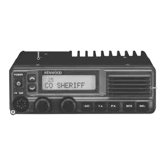
VHF APCO P25 TRANSCEIVER
TK-5710
TK-5710H
SERVICE MANUAL
TK-5710(B) with KCH-14
Cabinet (Lower)
(A01-2162-22)
TK-5710H(B)
Cabinet (Upper)
(A01-2163-21)
General .............................................................. 2
System Set-Up .................................................. 4
Realignment ..................................................... 5
Installation ................................................... 11
Disassembly For Repair .............................. 20
Circuit Description ...................................... 25
Semiconductor Data .................................. 33
Components Description .......................... 35
Parts List ......................................................... 37
EXPLODED VIEW ................................................ 50
PACKING ............................................................. 52
Adjustment .................................................... 54
Terminal Function ....................................... 70
(
)
B
(
)
B
Cabinet (Upper)
(A01-2161-22)
CONTENTS
©
2005-5 PRINTED IN JAPAN
B51-8727-00 ( S ) 618
Cabinet (Lower)
(A01-2164-21)
FINAL UNIT (X45-3750-10) : TK-5710 (B) ...... 74
FINAL UNIT (X45-3760-10) : TK-5710H (B) ... 76
Control Unit (X53-4120-10) ..................... 80
Tx-Rx Unit (X57-7030-10) ............................ 84
Schematic Diagram ...................................... 88
Interconnection Diagram ...................... 104
Block Diagram ............................................. 106
Level Diagram .............................................. 110
KCH-14 / KCH-15 / KES-6 ............................ 111
Specifications ............................. BACK COVER
This product uses Lead Free solder
Use this service manual
together with the
KCH-14/15 service manual
(B51-8728-00).
KCH-14
(Front panel kit)
Advertisement
Table of Contents

Subscribe to Our Youtube Channel
Related Manuals for Kenwood TK-5710


Summary of Contents for Kenwood TK-5710
- Page 1 (A01-2164-21) CONTENTS GENERAL .............. 2 PC BOARD SYSTEM SET-UP ..........4 FINAL UNIT (X45-3750-10) : TK-5710 (B) ..74 REALIGNMENT ............. 5 FINAL UNIT (X45-3760-10) : TK-5710H (B) ... 76 INSTALLATION ........... 11 CONTROL UNIT (X53-4120-10) ..... 80 DISASSEMBLY FOR REPAIR ......20 TX-RX UNIT (X57-7030-10) ......
-
Page 2: General
TK-5710 /5710H GENERAL INTRODUCTION PRE-INSTALLATION CONSIDERATIONS SCOPE OF THIS MANUAL 1. UNPACKING This manual is intended for use by experienced techni- Unpack the radio from its shipping container and check cians familiar with similar types of commercial grade com- for accessory items. If any item is missing, please contact munications equipment. - Page 3 5-1. Antenna system Control station. The antenna system selection depends on many factors and is beyond the scope of this manual. Your KENWOOD dealer can help you select an antenna system that will best serve your particular needs. 5-2. Radio location...
-
Page 4: System Set-Up
(KPG-43), and programming software (KPG-95D) are required for programming. (The frequency and signaling data are programmed for the transceiver.) KCT-23 DC cable KCT-23 M,M3 : TK-5710(B), KCT-23 M2,M4 : TK-5710H(B) See page 16 VGS-1 Are you using the voice guide & storage unit? -
Page 5: Realignment
TK-5710 /5710H REALIGNMENT 1. Modes 2. How to Enter Each Mode Mode Operation User mode User mode Power ON Panel test mode [PF1] + Power ON Panel test mode Panel tuning mode PC mode Received commands from PC Panel tuning mode... - Page 6 TK-5710 /5710H REALIGNMENT When data receiving to transceiver, the green LED is 3. Create a hole in the casing (as shown in the illustration) lights. then fit the cable into the hole. Replace the cover and secure it using the two screws.
-
Page 7: Clone Mode
TK-5710 /5710H REALIGNMENT Notes: 8. Clone Mode • Cannot be cloned if the overwrite password is pro- Programming data can be transferred from one trans- grammed to the slave. ceiver to another by connecting them via their microphone • "Model Name and Market Code", "Head Configuration" and jacks. -
Page 8: Self Programming Mode
TK-5710 /5710H REALIGNMENT 9-1. Enter to the self programming mode 9. Self Programming Mode Press and hold the [GRP ^ ] key while turning the trans- Write mode for frequency data and signaling etc. To be ceiver power ON. Ignoring whether the Read authorization used ONLY by the authorized service person maintaining the password is set or not, "PASSWORD"... -
Page 9: Key Operation
TK-5710 /5710H REALIGNMENT Key operation • Normal mode Item Zone- Channel RX Frequency TX Frequency Channel Type TX Mode Channel Spacing RX Signaling TX Signaling RX NAC TX NAC TG List No. [PF1] Unused [PF2] Go to the next item... - Page 10 TK-5710 /5710H REALIGNMENT Self programming mode flow chart ● [GRP ] + Power ON Input Password Read authorization password entry (6 digits) [PF2] Self programming mode [PF2] [PF3] Zone/Channel Zone selection Channel selection [PF2] When the [PF4] key is pressed, new data is written into memory.
-
Page 11: Installation
TK-5710 /5710H INSTALLATION 1. Front Panel Kit (KCH-14/15:Option) 1-1. Installing the KCH-14/15 front panel kit to the transceiver 1. Remove the upper case and lower case of the trans- ceiver. 2. Insert the lead wire with connector (W700) of the control unit (X53-412) into the connector (CN1) of the KCH-14 or KCH-15. - Page 12 TK-5710 /5710H INSTALLATION KCH-14 2. Remote kit (KRK-5:Option) The KRK-5 remote kit is used to remotely operate the POWER transceiver. The KRK-5 is connected to the KCH-14 or KCH- 15 with an optional KCT-22M (8 feet), KCT-22M2 (17 feet), or KCT-22M3 (25 feet) control cable.
- Page 13 TK-5710 /5710H INSTALLATION 2-3. Control cable (KCT-22) connection (Fig. 2-3) 1. Insert one connector of the control cable to the transceiver (with KRK-5) and the other to the display. KRK-5 main panel Connect the cable to the GND terminal with the screw (z) supplied with the control cable.
- Page 14 TK-5710 /5710H INSTALLATION 3. Dual Control Head Remote Kit Transceiver (KRK-6DH:Option) The KRK-6DH remote kit connects two displays (two KCH-14s or KCH-15s) to the transceiver. The KRK-6DH is connected to the KCH-14s or KCH-15s with two optional CN724 control cables. There are three version of the control cable :...
- Page 15 TK-5710 /5710H INSTALLATION Transceiver KRK-6DH main panel Cable fitting Display 2 Display 1 Cable fitting KCT-22 KCT-22 Control cable Control cable Fig. 3-2 4. Ignition Sense Cable (KCT-18:Option) The KCT-18 is an optional cable to use the following 3. Connect the square plug and rubber cap to the accessory...
- Page 16 TK-5710 /5710H INSTALLATION 5. Voice Guide & Storage Unit 6. Voice Scrambler Board Connection (VGS-1: Option) 1. Remove the upper case and upper packing of the transceiver. 5-1. Installing the VGS-1 unit in the transceiver 2. Two kinds of the scrambler board are available, and the 1.
- Page 17 TK-5710 /5710H INSTALLATION 7. ANI Board Connection 8. External Speaker (KES-5/6:Option) 1. Remove the upper case and upper packing of the The speaker output from the transceiver is as follows: transceiver. 1. The KCH-14 has a built-in speaker (3W/8 ohms).
- Page 18 TK-5710 /5710H INSTALLATION 8-3. Modification to increase the audio output of Short plug (9-pin) the control head The speaker output can be increased to 13W by moving jumper resistor (0 ohm) R74 to $R73 on the KCH-14 display unit (X54-349 A/3). In this case, the KCH-14 internal speaker...
- Page 19 TK-5710 /5710H INSTALLATION Short plug (9-pin) To KES-5 or KES-6 Black lead Crimp terminal Black/White lead (E23-0613-05) Fig. 8-4 9. Horn Alert Function The HR1 and HR2 pins of the accessory connector (9-pin) on the rear of the transceiver are connected to the relay (K700) and the maximum current is 1A.
-
Page 20: Disassembly For Repair
TK-5710 /5710H DISASSEMBLY FOR REPAIR Disassembly Procedure (TK-5710 (B)) ■ Removing the upper/ lower case and shield cover ■ Removing the Final unit (X45-375) 1. Remove the 9 screws z and 9 spacers x. 1. Remove the cables from the connector (CN702) of the 2. - Page 21 TK-5710 /5710H DISASSEMBLY FOR REPAIR Disassembly Procedure (TK-5710H (B)) ■ Removing the upper/ lower case and shield cover ■ Removing the Final unit (X45-376) 1. Remove the 12 screws z and 12 spacers x. 1. Remove the cables from the connector (CN702) of the 2.
-
Page 22: Disassembly For Repair
TK-5710 /5710H DISASSEMBLY FOR REPAIR Disassembly Procedure (TK-5710 (B) / 5710H (B)) Precautions for Reassembly ■ Removing the Control unit (X53-412) ■ Affixing the sheet (G11-4381-04) 1. Remove the 7 screws z. 1. Remove the covering paper from one side of the sheet z. - Page 23 /5710H DISASSEMBLY FOR REPAIR ■ Painting the lubricant (Part No.:490-0019-05) on ■ Affixing the sheet (G11-4378-04):TK-5710(B) only 1. Remove the covering paper of the sheet z. the groove of the case packing 2. Affix it to one side of chassis, so that the hollow of the Paint the lubricant to the position as shown in figure after sheet fits the convex of the chassis x.
- Page 24 TK-5710 /5710H DISASSEMBLY FOR REPAIR ■ Procedures after installing the case packing to ■ Sequence of tightening the screws for the the chassis upper / lower case to the chassis After installing the case packing to the chassis, confirm Install the upper / lower case to the chassis and tighten that all corners of the upper / lower packing are securely the screws in the order shown in the figure below.
-
Page 25: Circuit Description
TK-5710 /5710H CIRCUIT DESCRIPTION 1. Overview This transceiver is a VHF/FM/APCO portable transceiver The unit consists of receiver, transmitter, phase-locked designed to operate in the frequency range of 136 to loop (PLL) frequency synthesizer, base band parts, power 174MHz. supply, and control circuits. - Page 26 TK-5710 /5710H CIRCUIT DESCRIPTION 3-3. 1st IF selected. The 1st IF signal passing through these MCFs is amplified The 1st IF signal passes through the MCF (Monolithic by the IF amplifier (Q203) and goes into the FM IC (IC212). Crystal Filter) to remove unwanted signal.
- Page 27 TK-5710 /5710H CIRCUIT DESCRIPTION 3-6. Audio Amplifier Circuit The output signal from the D/A converter (IC738) passes through the amplifier (IC739), audio mute switch (Q732) and The AF signal from the CODEC IC (IC724) passes through analog switch (IC727), and then it is amplified by the audio the low-pass filter (IC729), analog switch (IC731) and amplifier (IC732).
- Page 28 CM coupler is a line for detecting forward wave and reduced more as this DC voltage rises. reflected wave. Forward wave is detected by D5, and is converted into FINAL UNIT (X45-375) COUPLER D1,D3, D12,D11 POWER REFL TX(CN1) MODULE Fig. 9 Final amplifier circuit: TK-5710 (B)
- Page 29 TX(CN1) MODULE Fig. 10 Final amplifier circuit: TK-5710H (B) 4-6. Temperature Protection Circuit : TK-5710 (B) 4-7. Temperature Protection Circuit : TK-5710H (B) To prevent thermal destruction of the power module To prevent thermal destruction of the power module (IC2), this circuit reduces APC voltage when temperature of (IC1) and final amplifier (Q1,Q2), this circuit reduces APC the power module (IC2) rises.
- Page 30 TK-5710 /5710H CIRCUIT DESCRIPTION RX VCO 2 output a 1st local receive signal. When the STR desired frequency. logic is low, the TX VCO output a transmit carrier. When the frequency is controlled by the PLL, the The voltage control terminals, "CV" and "ASSIST", are...
- Page 31 TK-5710 /5710H CIRCUIT DESCRIPTION written by the FPU (KPG-95D), and firmware program (User • Microphone amplifier AGC processing mode, Test mode, Tuning mode, etc.). This data must be • Audio mute processing rewritten when replacing the flash memory. • Modulation level processing ■...
- Page 32 TK-5710 /5710H CIRCUIT DESCRIPTION 8. Signaling Circuit 8-1. Encode (QT/DQT/DTMF/MSK) Each signaling data signal of QT, DQT, DTMF and MSK is generated by the DSP circuit, superposed on a modulation signal and output from pin 16 of the CODEC IC (IC724).
-
Page 33: Semiconductor Data
TK-5710 /5710H SEMICONDUCTOR DATA CPU:30625MGP213GP (Control unit IC703) Port Name Function Port Name Function Dual band switch − VREF A/D converter reference voltage SELF Self programming mode input terminal (L:Enable, H:Disable) − AVCC A/D converter power supply Bus control (Ready) −... - Page 34 TK-5710 /5710H SEMICONDUCTOR DATA Shift Register:BU4094BCFV (TX-RX unit IC600) Port Name Function Port Name Function FTEMP1 I(A/D) Temperature compensation 1 input STRB3 Latch clock input (Rising edge) ASQL I(A/D) Analog squelch input Serial data input I(A/D) VCO CV input Serial clock input (Rising edge)
-
Page 35: Components Description
TK-5710 /5710H COMPONENTS DESCRIPTION Control unit (X53-4120-10) Ref. No. Part name Description Ref. No. Part name Description Q709 Transistor DC switch (SBC) Q710 Transistor DC switch (SBC) IC700 RTC IC Q711 Transistor DC switch (IGN) IC701 EEPROM Q712 Transistor DC switch (IGN) - Page 36 Diode Local switch IC205~207 IC Multiplexer A400 Double balanced mixer IC209~211 IC Multiplexer IC212 FM IC IC213 Buffer Final unit (X45-3750-10) : TK-5710 (B) IC214 Multiplexer Ref. No. Part name Description IC400 PLL IC IC401 Rheostat APC comparator IC402 OP AMP...
-
Page 37: Parts List
TK-5710 /5710H PARTS LIST CAPACITORS CC 45 TH 1H Capacitor value Color* CC45 010 = 1pF 0 = 22pF 1 = Type ... ceramic, electrolytic, etc. 100 = 10pF 4 = Voltage rating Multiplier 2 = Shape ... round, square, ect. - Page 38 SCREW SET ACCESSORY N87-2612-46 BRAZIER HEAD TAPTITE SCREW(SHIELD) W09-0971-05 LITHIUM CELL(X53) 1B,2B N87-3008-46 BRAZIER HEAD TAPTITE SCREW(DC/ACC,ANT) FINAL UNIT ( X45-3750-10 ) :TK-5710 ( B ) N99-0365-05 SCREW SET ACCESSORY W09-0971-05 LITHIUM CELL(X53) C4 -6 CK73FB1H102K CHIP C 1000PF K ∗...
- Page 39 TK-5710 /5710H PARTS LIST FINAL UNIT (X45-3750-10) FINAL UNIT (X45-3760-10) Address Parts No. Description Destination Address Parts No. Description Destination Ref. No. Ref. No. parts parts C93-0562-05 CHIP C 15PF TA75W01FU MOS-IC ∗ C93-0563-05 CHIP C 18PF RA60H1317M1-23 MOS-IC(POWER MODULE)
- Page 40 RELAY TERMINAL S1R104J475H THERMISTOR ∗ E40-6429-05 FLAT CABLE CONNECTOR CN10 E23-1118-05 TERMINAL CONTROL UNIT ( X53-4120-10 ) : TK-5710 ( B ) / 5710H ( B ) ∗ E37-1218-05 LEAD WIRE WITH CONNECTOR ∗ L41-4778-08 SMALL FIXED INDUCTOR(47NH) C601 CK73HB1A104K CHIP C 0.10UF K...
- Page 41 TK-5710 /5710H PARTS LIST CONTROL UNIT (X53-4120-10) Address Parts No. Description Destination Address Parts No. Description Destination Ref. No. Ref. No. parts parts C764-767 CK73FB0J106K CHIP C 10UF C862 CC73GCH1H101J CHIP C 100PF C768 CK73HB1A104K CHIP C 0.10UF K C863...
- Page 42 TK-5710 /5710H PARTS LIST CONTROL UNIT (X53-4120-10) Address Parts No. Description Destination Address Parts No. Description Destination Ref. No. Ref. No. parts parts R604,605 RK73HB1J100J CHIP R J 1/16W R709 RK73GB1J104J CHIP R 100K J 1/16W R606 R92-1368-05 CHIP R...
- Page 43 TK-5710 /5710H PARTS LIST CONTROL UNIT (X53-4120-10) Address Parts No. Description Destination Address Parts No. Description Destination Ref. No. Ref. No. parts parts R790 RK73GB1J102J CHIP R 1.0K J 1/16W R908 RK73GB1J103J CHIP R J 1/16W R791-810 RK73HB1J101J CHIP R...
- Page 44 IC709 XC6209B152M MOS-IC Q735,736 UM6K1N IC710 XC6204B332M MOS-IC IC711 XC6204B252M MOS-IC ∗ TX-RX UNIT ( X57-7030-10 ) :TK-5710 ( B ) / 5710 H ( B ) IC712 29LV160BE90PBT ROM IC IC713 TC7S08FU MOS-IC C150 CC73GCH1H150J CHIP C 15PF IC714...
- Page 45 TK-5710 /5710H PARTS LIST TX-RX UNIT (X57-7030-10) Address Parts No. Description Destination Address Parts No. Description Destination Ref. No. Ref. No. parts parts C171 CK73GB1H103K CHIP C 0.010UF K C270 CC73GCH1H470J CHIP C 47PF C200 CC73GCH1H150J CHIP C 15PF C271...
- Page 46 TK-5710 /5710H PARTS LIST TX-RX UNIT (X57-7030-10) Address Parts No. Description Destination Address Parts No. Description Destination Ref. No. Ref. No. parts parts C438 CC73GCH1H300J CHIP C 30PF C605 CK73GB1C104K CHIP C 0.10UF K C439 CC73GCH1H150J CHIP C 15PF C606...
- Page 47 TK-5710 /5710H PARTS LIST TX-RX UNIT (X57-7030-10) Address Parts No. Description Destination Address Parts No. Description Destination Ref. No. Ref. No. parts parts L421 L41-3398-08 SMALL FIXED INDUCTOR(3.3UH) R225,226 R92-1252-05 CHIP R 0 OHM J 1/16W L422 L41-2798-08 SMALL FIXED INDUCTOR(2.7UH)
- Page 48 TK-5710 /5710H PARTS LIST TX-RX UNIT (X57-7030-10) Address Parts No. Description Destination Address Parts No. Description Destination Ref. No. Ref. No. parts parts R405 RK73GB1J563J CHIP R J 1/16W R500,501 R92-0670-05 CHIP R 0 OHM R406 RK73GB1J103J CHIP R J 1/16W...
- Page 49 TK-5710 /5710H PARTS LIST TX-RX UNIT (X57-7030-10) Address Parts No. Description Destination Address Parts No. Description Destination Ref. No. Ref. No. parts parts Q400 2SK879(GR,Y) Q401 DTA144EE DIGITAL TRANSISTOR Q402 DTC144EE DIGITAL TRANSISTOR Q403 2SC5108(Y) TRANSISTOR Q404,405 RN47A4 TRANSISTOR Q406,407...
-
Page 50: Exploded View
TK-5710 /5710H EXPLODED VIEW (TK-5710(B)) 62 x2 62 x2 TX-RX unit Final unit KCH-14 KCH-15 Control unit A : N09-2292-05 B : N32-3008-45 D : N35-3006-46 E : N67-3008-46 H : N87-2606-46 I : N87-2612-46 J : N87-3008-46 Parts with the exploded numbers larger than 700 are not supplied. - Page 51 TK-5710 /5710H EXPLODED VIEW (TK-5710H(B)) 62x3 62x3 I x2 Final unit TX-RX unit KCH-14 KCH-15 Control unit A : N09-2292-05 B : N32-3008-45 C : N35-2604-43 E : N67-3008-46 F : N68-3008-46 G : N68-4006-46 H : N87-2606-46 62x2 I : N87-2612-46...
-
Page 52: Packing
TK-5710 /5710H PACKING (TK-5710(B)) 50. INNER CARTON CASE (H02-0626-04) 63. SCREW SET (N99-0365-05) 16. SHORT PLUG (SP) 705. PAMPHLET (E37-0733-05) 38. SHEET (G11-4379-04)x2 10. INSTRUCTION MANUAL (B62-1816-10) 52. PACKING FIXTURE (H12-3183-02) 707. PROTECTION BAG 51. PACKING FIXTURE (H12-3176-02) 52. PACKING FIXTURE (H12-3183-02) 57. - Page 53 TK-5710 /5710H PACKING (TK-5710H(B)) 50. INNER CARTON CASE (H02-0626-04) 63. SCREW SET (N99-0365-05) 16. SHORT PLUG (SP) 706. PAMPHLET (E37-0733-05) 38. SHEET (G11-4379-04)x2 10. INSTRUCTION MANUAL (B62-1816-10) 53. PACKING FIXTURE (H12-3185-02) 708. PROTECTION BAG 51. PACKING FIXTURE (H12-3176-02) 53. PACKING FIXTURE (H12-3185-02) 58.
-
Page 54: Adjustment
TK-5710 /5710H ADJUSTMENT ■ Key operation Controls “FNC”not appears • KCH-14 (Basic control panel) Function Display Power [Selector] Wide/Narrow/APCO Wide :“W”appears switch Narrow:“N”appears APCO :“A”appears POWER Shifts to the Panel tuning mode − [GRP ] [GRP ] Squelch off MON icon appears... - Page 55 TK-5710 /5710H ADJUSTMENT • LED indicator • Test Signaling Red LED Lights during transmission. Signaling APCO/ Green LED Lights when there is carrier. Analog None None Analog • LCD display in the panel test mode None 100Hz Square wave Analog W : Wide QT 67.0Hz...
- Page 56 TK-5710 /5710H ADJUSTMENT ■ Key operation Panel Tuning Mode Function The transceiver is adjusted in this mode. [Selector] Unused ■ Preparations for tuning the transceiver [GRP ] Exit the panel tuning mode and shift to the Before attempting to tune the transceiver, connect the panel test mode.
- Page 57 TK-5710 /5710H ADJUSTMENT ■ Adjustment item and Display (∗∗∗: 1~256) Adjustment item Display Wide/Narrow/APCO Tuning point Note ∗∗∗ TX assist voltage VATX Wide VARX u ∗∗∗ RX assist voltage (Upper) Wide ∗∗∗ RX assist voltage (Lower) VARX l Wide ∗∗∗...
- Page 58 TK-5710 /5710H ADJUSTMENT ■ Flow Chart [PF1]:Not stored [PF1]:Not stored [PF5]:Not stored 5 reference level 3 reference level [GRPV] TX V assist Wide adjustments adjustments [PF1]:Not stored [PF2]:Not stored [PF2]:Not stored [PF1]:Not stored [PF5]:Not stored 5 reference level [PF5]:Stored RX V assist (Upper)
- Page 59 55.). This test signal has a peak devia- tion equal to π /2 1800Hz = 2827Hz. Adjustment Points CN10 CLKC FINAL UNIT (X45-3750-10) 32K OUT : TK-5710(B) Component side CONTROL UNIT (X53-4120-10) Component side CN152 CN10 CN150...
- Page 60 4Ω Dummy Load Approx. 4Ω, 30W Regulated Power Supply 13.6V (TK-5710 (B)), 13.4V (TK-5710H (B)), approx. 30A (adjusted from 9 to 20V) Useful if ammeter equipped Caution Since the RX AF output is a BTL output, there is a DC Component.
- Page 61 Terminal Unit Parts Method equipment 1. Setting 1) Connect the front panel kit (KCH-14 or KCH-15) to the TK-5710(B)/5710H(B) transceiver. 2) Power supply voltage •TK-5710(B) Power input connector:13.6V •TK-5710H(B) Power input connector:13.4V 3) SSG standard modulation [Wide] MOD:1kHz, DEV:3kHz [Narrow] MOD:1kHz, DEV:1.5kHz 2.
- Page 62 TK-5710 /5710H ADJUSTMENT Measurement Adjustment Item Condition Test- Specifications/Remarks Unit Terminal Unit Parts Method equipment 4. MCF 1) CH-Sig:1-1 Spectrum Rear TX-RX L225 Adjust the coils •Wide Spectrum analyzer setting analyzer panel L227 to obtain the Center-f : 49.95MHz L229...
- Page 63 TK-5710 /5710H ADJUSTMENT Transmitter Section Measurement Adjustment Item Condition Test- Specifications/Remarks Unit Terminal Unit Parts Method equipment 1. Frequency 1) Adj item:[W TXF] f.counter Rear Front [PF3], Center frequency Note:After replacing adjust Adjust:[***] panel panel [PF4] ±50Hz the VCXO (X200) align PTT:ON frequency.
- Page 64 TK-5710 /5710H ADJUSTMENT Measurement Adjustment Item Condition Test- Specifications/Remarks Unit Terminal Unit Parts Method equipment 6. Max DEV 1) Adj item:[W FMWD] Deviation Rear Front [PF3], 4.05kHz ±50Hz adjust Adjust:[***] meter panel panel [PF4] (According to the large +, −) •Wide...
- Page 65 TK-5710 /5710H ADJUSTMENT Measurement Adjustment Item Condition Test- Specifications/Remarks Unit Terminal Unit Parts Method equipment 9. QT deviation 1) Adj item:[W QTW] Power meter Rear Front [PF3], 0.75kHz ±50Hz adjust Adjust:[***] Deviation panel panel [PF4] •Wide Deviation meter filter meter...
- Page 66 TK-5710 /5710H ADJUSTMENT Measurement Adjustment Item Condition Test- Specifications/Remarks Unit Terminal Unit Parts Method equipment 12.MSK 1) Adj item:[W MSKW] Power meter Rear Front [PF3], 3.0kHz ±100Hz deviation Adjust:[***] Deviation panel panel [PF4] adjust Deviation meter filter meter •Wide LPF:15kHz...
- Page 67 TK-5710 /5710H ADJUSTMENT Measurement Adjustment Item Condition Test- Specifications/Remarks Unit Terminal Unit Parts Method equipment 2. RSSI 1) Adj item:[W RSSI] Rear Front [PF5] After input (Reference) Adjust:[***] AF VTVM panel EXT.SP panel signal from SSG, adjust 2) Adj item:[WL RSSI]t Oscilloscope press [PF5] key.
- Page 68 TK-5710 /5710H ADJUSTMENT Measurement Adjustment Item Condition Test- Specifications/Remarks Unit Terminal Unit Parts Method equipment 6. Sensitivity 1) CH-Sig:1-1 Rear Check 12dB SINAD or more Check SSG output:-117dBm(0.32µV) AF VTVM panel EXT.SP •Wide (MOD:1kHz/±3kHz) Oscilloscope 2) CH-Sig:2-1 3) CH-Sig:3-1 •Narrow 4) CH-Sig:1-1 SSG output:-117dBm(0.32µV)
- Page 69 TK-5710 /5710H ADJUSTMENT Measurement Adjustment Item Condition Test- Specifications/Remarks Unit Terminal Unit Parts Method equipment 8. Squelch 1) Adj item:[W SQTW] Rear Front [PF5] After input After adjusting SQL, (Tight) Adjust:[***] AF VTVM panel EXT.SP panel signal from SSG, check SQL open/close.
-
Page 70: Terminal Function
Final unit (X45-3750-10): TK-5710(B) Control unit (X53-4120-10) Name Description Name Description CN1 (to TX-RX unit CN150) CN702 (to TK-5710(B) or TK-5710H(B) Final unit W2) TX drive input Power supply input CN2 (to TX-RX unit CN200) (TK-5710(B):13.6V/ TK-5710H(B):13.4V) RX signal output Power supply input (TK-5710(B):13.6V/ TK-5710H(B):13.4V) - Page 71 TK-5710 /5710H TERMINAL FUNCTION Name Description Name Description − Enable output (Active Low) 9,10 E − USEL UART speed select 11,12 NC No connection − (H:115200bps, L:19200bps) − VRST Reset signal output Common 5V − − Digital GND 15~19 NC No connection −...
- Page 72 Final unit temperature 2 − Control voltage of VCO − MIC signal input − MIC GND CN601 (to TK-5710(B) or TK-5710H(B) Final unit CN9) TX power control voltage − − TX-RX unit (X57-7030-10) 8V output during transmission − 8V output during transmission...
- Page 73 I/O Auxiliary Input/output 6 (FPU selectable) BTL output for external speaker B (PA) − Active Low with 47kΩ pull-up to 5V L 0.8V, H 4.2V Switched B (TK-5710(B):13.6V±15% / TK-5710H(B):13.4V±15%) 2A max. AUXO 2 Auxiliary output 2 (FPU selectable) Active Low:Open Collector (500mA max.)
- Page 74 TK-5710 /5710H PC BOARD FINAL UNIT (X45-3750-10) : TK-5710(B) Component side view (J72-0944-09) J72-0944-09 FINAL UNIT (X45-3750-10) : TK-5710(B) Foil side view (J72-0944-09) J72-0944-09...
-
Page 75: Pc Board Final Unit (X45-3750-10) : Tk-5710 (B)
TK-5710 /5710H PC BOARD FINAL UNIT (X45-3750-10) : TK-5710(B) Component side view (J72-0944-09) CN10 Ref. No. Address Component side Layer 1 Layer 2 Layer 3 Layer 4 Foil side FINAL UNIT (X45-3750-10) : TK-5710(B) Foil side view (J72-0944-09) Ref. No. Address... - Page 76 TK-5710 /5710H TK-5710 /5710H PC BOARD PC BOARD FINAL UNIT (X45-3750-10) : TK-5710(B) FINAL UNIT (X45-3750-10) : TK-5710(B) Component side view (J72-0944-09) Component side view (J72-0944-09) J72-0944-09 CN10 Ref. No. Address Component side Layer 1 Layer 2 Layer 3 Layer 4...
-
Page 77: Final Unit (X45-3760-10) : Tk-5710H (B)
TK-5710 /5710H PC BOARD FINAL UNIT (X45-3760-10) : TK-5710H(B) Component side view (J72-0945-09) +B +B J72-0945-09... - Page 78 TK-5710 /5710H PC BOARD FINAL UNIT (X45-3760-10) : TK-5710H(B) Component side view (J72-0945-09) CN10 Ref. No. Address REV FWD Component side Layer 1 Layer 2 Layer 3 Layer 4 Foil side...
- Page 79 TK-5710 /5710H TK-5710 /5710H PC BOARD PC BOARD FINAL UNIT (X45-3760-10) : TK-5710H(B) FINAL UNIT (X45-3760-10) : TK-5710H(B) Component side view (J72-0945-09) Component side view (J72-0945-09) CN10 Ref. No. Address REV FWD +B +B J72-0945-09 Component side Layer 1 Layer 2...
- Page 80 TK-5710 /5710H PC BOARD FINAL UNIT (X45-3760-10) : TK-5710H(B) Foil side view (J72-0945-09)
- Page 81 TK-5710 /5710H PC BOARD FINAL UNIT (X45-3760-10) : TK-5710H(B) Foil side view (J72-0945-09) J72-0945-09 Component side Layer 1 Layer 2 Layer 3 Layer 4 Foil side...
- Page 82 TK-5710 /5710H TK-5710 /5710H PC BOARD PC BOARD FINAL UNIT (X45-3760-10) : TK-5710H(B) FINAL UNIT (X45-3760-10) : TK-5710H(B) Foil side view (J72-0945-09) Foil side view (J72-0945-09) J72-0945-09 Component side Layer 1 Layer 2 Layer 3 Layer 4 Foil side...
-
Page 83: Control Unit (X53-4120-10)
TK-5710 /5710H PC BOARD CONTROL UNIT (X53-4120-10) Component side view (J72-0942-29) R774 EMUI/OFF EMUO R777 DGND DGND DGND 3.3D L716 CLKC DGND C771 + TRST CN728 R831 D652 C776 R832 R833 D653 IC715 R817 R834 R818 C783 F701 C773 R835... - Page 84 TK-5710 /5710H PC BOARD CONTROL UNIT (X53-4120-10) Component side view (J72-0942-29) R960 F700 D719 CN702 D720 R709 C706 C704 R701 Q708 Scrambler R707 R706 C707 R704 RXAF C863 BC1 LOK TXO RXEI BC3 BUSY STON TCONT INH CN786 C906 PTOS...
- Page 85 TK-5710 /5710H TK-5710 /5710H PC BOARD PC BOARD CONTROL UNIT (X53-4120-10) CONTROL UNIT (X53-4120-10) Component side view (J72-0942-29) Component side view (J72-0942-29) R774 EMUI/OFF EMUO R777 DGND R960 DGND F700 DGND L716 3.3D CLKC DGND C771 + CN728 TRST R831...
- Page 86 TK-5710 /5710H PC BOARD CONTROL UNIT (X53-4120-10) Foil side view (J72-0942-29) D706 R722 C763 + D711 C717 R713 IC707 C875 D734 R771 C910 Q730 C711 D708 R726 Q709 Q707 R724 Q728 C869 L726 C762 C788 L728 L727 C716 IC717 L729...
- Page 87 TK-5710 /5710H PC BOARD CONTROL UNIT (X53-4120-10) Foil side view (J72-0942-29) D706 R731 R729 R728 R722 D711 D712 C745 C733 R730 R713 C734 R790 D713 C910 C911 D708 R726 R724 C808 L650 C846 R839 C748 IC728 C998 Q717 Q714 C749...
- Page 88 TK-5710 /5710H TK-5710 /5710H PC BOARD PC BOARD CONTROL UNIT (X53-4120-10) CONTROL UNIT (X53-4120-10) Foil side view (J72-0942-29) Foil side view (J72-0942-29) D706 R731 R729 R728 R722 C763 + D711 D712 C745 C717 C733 R730 R713 C734 IC707 C875 R790...
-
Page 89: Tx-Rx Unit (X57-7030-10)
TK-5710 /5710H PC BOARD TX-RX UNIT (X57-7030-10) Component side view (J72-0943-09) CN150 C165 Q151 C159 Q150 C151 R151 C152 R153 R168 R160 R164 R155 C160 C163 R494 C513 Q201 D436 C228 C225 C236 C241 R226 L212 L211 R219 C232 L213... - Page 90 TK-5710 /5710H PC BOARD TX-RX UNIT (X57-7030-10) Component side view (J72-0943-09) CN601 CN152 CN200 L223 L222 L221 L224 XF201 L226 NARROW L228 XF201 L230 L225 XF200 L227 L229 XF200 L231 WIDE Q213 R276 IC211 R278 C284 IC214 R299 R309 IC210...
- Page 91 TK-5710 /5710H TK-5710 /5710H PC BOARD PC BOARD TX-RX UNIT (X57-7030-10) TX-RX UNIT (X57-7030-10) Component side view (J72-0943-09) Component side view (J72-0943-09) CN601 CN150 CN152 CN200 C165 Q151 C159 Q150 C151 R151 C152 R153 R168 R160 R164 R155 C160 C163...
- Page 92 TK-5710 /5710H PC BOARD TX-RX UNIT (X57-7030-10) Foil side view (J72-0943-09) C200 Q200 C210 R205 C212 C206 C207 C202 R201 D202 C215 C218 C211 R209 L208 L203 L205 R202 D200 D201 C220 C329 C204 C205 R211 C222 R282 R287 C264...
- Page 93 TK-5710 /5710H PC BOARD TX-RX UNIT (X57-7030-10) Foil side view (J72-0943-09) C636 R622 C167 C169 R171 C168 R209 C448 Q409 C451 R521 R432 C443 C430 R442 L437 Q405 C456 Q408 R431 C442 R441 Q412 Q404 R454 L435 C463 C429 R480...
- Page 94 TK-5710 /5710H TK-5710 /5710H PC BOARD PC BOARD TX-RX UNIT (X57-7030-10) TX-RX UNIT (X57-7030-10) Foil side view (J72-0943-09) Foil side view (J72-0943-09) C636 R622 C167 C200 C169 R171 C168 Q200 C210 R205 C212 C206 C207 C202 R201 D202 C211 C215...
-
Page 95: Schematic Diagram
TK-5710 /5710H SCHEMATIC DIAGRAM FINAL UNIT (X45-3750-10):TK-5710(B) POWER MODULE RA60H1317M1-23 ANT SW MA4PH633 E04-0154-05 MA4PH633 ANT SW R:0V T:1.55V R:0V R:13.59V T:4.51V T:12.45V E40-6429-05 R:4.84V ANT SW ANT SW FTEMP2 T:4.88V FTEMP1 E04-0154-05 R:0.04V T:4.67V 100k R:0V T:5.45V PROTECTOR OF VOLTAGE... - Page 96 TK-5710 /5710H SCHEMATIC DIAGRAM FINAL UNIT (X45-3750-10):TK-5710(B) FORWARD WAVE RECTIFICATION HSM88AS CN10 REFLECTED WAVE RECTIFICATION HSM88AS 1000p COMBINER E23-0902-05 R:13.6V T:12.44V SURGE ABSORPTION 13.6V PROTECT OF REVERSE CONNECTION APC COMPARATOR TA75W01FU R:0V T:0.46V IN2+ E37-0705-05 IN2- IN1+ 100k OUT-B IN1-...
- Page 97 TK-5710 /5710H SCHEMATIC DIAGRAM FINAL UNIT (X45-3750-10):TK-5710(B) POWER MODULE FORWARD WAVE RECTIFICATION RA60H1317M1-23 HSM88AS ANT SW CN10 MA4PH633 E04-0154-05 MA4PH633 ANT SW R:0V T:1.55V REFLECTED WAVE R:0V R:13.59V RECTIFICATION T:4.51V T:12.45V HSM88AS 1000p COMBINER E40-6429-05 R:4.84V ANT SW ANT SW FTEMP2 T:4.88V...
- Page 98 TK-5710 /5710H SCHEMATIC DIAGRAM FINAL UNIT (X45-3760-10):TK-5710H(B) R:13.4V T:12.75V TX DRIVE AMP FINAL AMP RA13H1317M-31 RD100HHF1-02 R:0V R:13.4V T:1.55V T:12.75V E04-0154-05 1000p R:13.4V T:12.75V RD100HHF1-02 FINAL AMP R:0V T:3.46V R:0V T:2.49V 2.7k E40-6429-05 FTEMP2 FTEMP1 DC AMP & R:0V APC COMPARATOR T:4.62V...
- Page 99 TK-5710 /5710H SCHEMATIC DIAGRAM FINAL UNIT (X45-3760-10):TK-5710H(B) FORWARD WAVE RECTIFICATION HSM88AS CN10 ANT SW MA4P4002F 180p 100p 180p HSM88AS R:0V T:1.45V REFLECTED WAVE RECTIFICATION D8,9 ANT SW R:0V R:0V E04-0154-05 T:1.41V T:1.99V COMBINER MA2S111 R:13.4V E23-0902-05 T:13.32V SURGE ABSORPTION 13.4V...
- Page 100 TK-5710 /5710H SCHEMATIC DIAGRAM FINAL UNIT (X45-3760-10):TK-5710H(B) R:13.4V T:12.75V FORWARD WAVE RECTIFICATION TX DRIVE AMP FINAL AMP RA13H1317M-31 HSM88AS RD100HHF1-02 R:0V R:13.4V T:1.55V T:12.75V CN10 ANT SW MA4P4002F E04-0154-05 180p 180p 100p 1000p R:13.4V T:12.75V HSM88AS R:0V T:1.45V REFLECTED WAVE...
- Page 101 TK-5710 /5710H SCHEMATIC DIAGRAM CONTROL UNIT (X53-4120-10) CN702 E40-5703-05 3.3D 13.33V CN709 R774 470p E40-6050-05 C760 D720 REVERSE EMUi/OFF EMU1 CURRENT F700 Q713 PREVENTION F53-0278-05 EMUo EMU0 2SJ506(S) D719 R777 DGND 5.0A VOLTAGE REGULATOR (5V) DC SW 13.10V D724 (SB)
- Page 102 TK-5710 /5710H SCHEMATIC DIAGRAM CONTROL UNIT (X53-4120-10) 3.3D 3.3D TEMPERATURE DET IC702 MM1522XURE 0.80V VOUT D721 VOLTAGE PROTECTION 4.94V VOLTAGE REGULATOR (RTC5V) IC741 4.99V NJM78L05UA R650 R762 PToS R763 D715-717 REVERSE CURRENT PREVENTION C758 R789 CN701 D716 0.1u 1SS388 R811 4.94V...
- Page 103 TK-5710 /5710H SCHEMATIC DIAGRAM CONTROL UNIT (X53-4120-10) 3.3D 3.42Vpp SCLK1 0.01u C784 3.3V CVSS9 DVSS7 BCLKX1 DVDD5 CVSS8 PToS R831 CVDD5 INT3 INT2 R832 INT1 R833 INT0 R834 HBIL IACK DSPINT BDX2 SRESET BDX0 SDTi 1.5V DVSS6 CVDD6 DVDD4 R817...
- Page 104 TK-5710 /5710H SCHEMATIC DIAGRAM CONTROL UNIT (X53-4120-10) R865 VREF D727 R845 100k C800 4.7k 0.1u Q715 R652 2SC4738(GR) ANALOG SW RB706F-40 (SCRAMBLER) 470k Q720 Q715,716 C798 R625 2SJ243 C803 D277,728 R861 AUTO GAIN CONTROL TX AGC DETECTION 4.7u Q716 2SA1832(GR)
- Page 105 TK-5710 /5710H SCHEMATIC DIAGRAM CONTROL UNIT (X53-4120-10) VREF C825 R890 OP AMP 680k (MOD/RX AF) OP AMP (RX AF) R920 IC729 IC723 TC75W51FU 2.0V 2.02V TA75S01F R896 R912 IN(-) 270k C858 R932 R663 SCSW IN(+) R913 3900p 4.95V 2.02V 180k 4.93V...
- Page 106 TK-5710 /5710H SCHEMATIC DIAGRAM CONTROL UNIT (X53-4120-10) SHIFT REGISTER RXD3 IC717 BU4094BCFV DC SW (BEEPS) Q714 Q717 Q735 DTC114YE DTC114YE UM6K1N DC SW ANALOG SW (SCSW) Q714,717 (SCRAMBLER) BUFFER (RXD3) Q736 IC731 UM6K1N TC7W66FK 3.29V 4.95V 1 IN_oUT1 R662 2 oUT_IN1...
- Page 107 TK-5710 /5710H SCHEMATIC DIAGRAM CONTROL UNIT (X53-4120-10) C844 22u10 22u10 C848 AUDIO POWER AMP R916 IC732 ANALOG SW TDA8561Q IC727 BU4053BCFV 4.94V C841 10u10 C847 0.01u D732 D731 VOLTAGE VOLTAGE PROTECTION 12.65V PROTECTION RX AUDIO MUTE SW SHIFT Q729 REGISTER...
- Page 108 TK-5710 /5710H SCHEMATIC DIAGRAM CONTROL UNIT (X53-4120-10) CN783 E40-5066-05 L724 i GN L725 L726 L727 L728 o S2 L729 o S1 L730 L731 L732 i RS CN728 E40-5960-05 AUXi/o6 AUXi/o6 AUXi/o7 AUXi/o7 AUXi/o1 AUXi/o1 AUXi/o2 AUXi/o2 RXD3 RXD3 AUXi/o3 AUXi/o\3...
- Page 109 TK-5710 /5710H SCHEMATIC DIAGRAM CONTROL UNIT (X53-4120-10) CN702 E40-5703-05 3.3D 3.3D 3.3D 3.3D C844 22u10 C848 22u10 AUDIO POWER AMP R916 CN783 IC732 E40-5066-05 13.33V ANALOG SW TDA8561Q L724 i GN L725 BU4053BCFV IC727 D727 R865 VREF VREF L726 R845 100k 4.94V...
- Page 110 TK-5710 /5710H SCHEMATIC DIAGRAM TX-RX UNIT (X57-7030-10) 5.02V Q406 R596 R590 2SJ347 L434 TX2RX2 Q404,406 VCO1/2 SW 4.97V Q598,599 Q404 4.81V RN47A4 LOCK DETECTION L435 TX1RX1 R595 R594 Q598 R423 2SA1832(GR) Q599 DTC144EE Q407 2SJ347 L436 TXVCO Q405,407 VCO TX/RX SW...
- Page 111 TK-5710 /5710H SCHEMATIC DIAGRAM TX-RX UNIT (X57-7030-10) 136 - < 155MHz:7.13V 155 - 174MHz:0V Q409 RN47A4 RXVCO 1 TX2RX2 RIPPLE FILTER R432 7.21V 7.92V Q412 2SC4116(GR) R455 D408,409 7.15V TX1RX1 7.88V RX VCO 1/2 SW 136 - < 155MHz:0V 155 - 174MHz:7.13V 7.78V...
- Page 112 TK-5710 /5710H SCHEMATIC DIAGRAM TX-RX UNIT (X57-7030-10) D435,436 RF AMP RF AMP LOCAL SW R:0V R:0V Q151 Q150 T:2.04V T:1.03V D435 2SC3357(RF) 2SC3357(RF) 4.92V HVC131 C150 C151 C152 C159 R151 R153 D436 HVC131 R:0V T:7.92V R:0V R:0V R155 R164 T:5.20V T:7.31V...
- Page 113 TK-5710 /5710H SCHEMATIC DIAGRAM TX-RX UNIT (X57-7030-10) C165 L154 C168 C169 R171 CN150 1000p 1000p VOLTAGE REGULATOR IC601 TA7805F 5.0V 8.0V SHIFT REGISTER IC600 5V AVR BU4094BCFV CN152 5.02V STRB R:0V R:7.91V 4.93V 8R SW 8T SW T:7.91V T:0V DATA...
- Page 114 TK-5710 /5710H SCHEMATIC DIAGRAM TX-RX UNIT (X57-7030-10) 136 - < 155MHz:7.13V 5.02V 155 - 174MHz:0V R596 R590 Q406 Q409 RN47A4 2SJ347 L434 RXVCO 1 TX2RX2 TX2RX2 RIPPLE FILTER Q404,406 R432 7.21V 7.92V Q412 VCO1/2 SW 4.97V 2SC4116(GR) R455 Q598,599 Q404 4.81V...
-
Page 115: Interconnection Diagram
TK-5710 /5710H INTERCONNECTION DIAGRAM CNVSS RESET SCLCK CN728 TXDI E40-5960-05 BUSY RXD2 AUXo2 TXD2 Note 1) AUXo1 CN705 AUXI/o9 E40-6202-05 E56-0410-15 TRST DGND AUXI/o5 3.3D AUXI/o8 AUXI/o4 DGND TXD3 X54-3490-20 A/3(KCH-14) AUXI/o3 DGND X54-3500-20 A/2(KCH-15) RXD3 AUXI/o2 DGND EMUo AUXI/o1... - Page 116 TK-5710 /5710H INTERCONNECTION DIAGRAM 1 14 RXD2 AUXo2 TXD2 AUXo1 4 17 AUXI/o9 7 20 AUXI/o5 AUXI/o8 AUXI/o4 TXD3 AUXI/o3 10 23 RXD3 AUXI/o2 AUXI/o1 AUXI/o7 AUXI/o6 TK-5710(B) E37-0707-05 E23-0902-05 13.6V TK-5710H(B) E23-1116-05 CN150:TK-5710(B) 13.4V CN152:TK-5710H(B) E04-0154-05 E04-0154-05 FTEMP2 FTEMP1...
- Page 117 TK-5710 /5710H TK-5710 /5710H INTERCONNECTION DIAGRAM INTERCONNECTION DIAGRAM CNVSS RESET SCLCK CN728 TXDI E40-5960-05 BUSY 1 14 RXD2 RXD2 AUXo2 AUXo2 TXD2 TXD2 Note 1) AUXo1 CN705 AUXo1 AUXI/o9 E40-6202-05 4 17 AUXI/o9 E56-0410-15 TRST DGND 7 20 AUXI/o5 3.3D...
-
Page 118: Block Diagram
TK-5710 /5710H BLOCK DIAGRAM TK-5710 BLOCK DIAGRAM CONTROL UNIT TX-RX UNIT Q404 RN47A4 Q406 2SJ347 F700 Q713 2SJ506 F53-0278-05 DSA3A1-FK IC706 1A Max IC400 2W Max LM2940T-8.0 LMX2352TMX/NP Q409 PROTECT RN47A4 EP CLK DAT Q412 RX VCO 1 2SC4116GR 22ZR-10D... - Page 119 TK-5710 /5710H BLOCK DIAGRAM FINAL UNIT 136-174MHz Q413, 414 2SK508NV(52K) ASSIST COUPLER VCO1/ 2 D1,D3, Q151 Q417 Q41 9 Q150 Q416 D435,D436 D12,D17 2SC5108(Y) 2SC3357(RF) 2SC3357(RF) 2SC5108(Y) RA60H1317M1 MA4PH633 2SK508NV(K52) HVC131 Buff Front POWER REFL MODULE ASSIST Q403 Q418 16.8MHz...
-
Page 120: Display Unit
TK-5710 /5710H BLOCK DIAGRAM TK-5710 H BLOCK DIAGRAM TX-RX UNIT CONTROL UNIT Q404 RN47A4 Q406 2SJ347 F700 Q713 2SJ506 F53-0278-05 DF25V60 IC706 1A Max IC400 LM2940T-8.0 2W Max LMX2352TMX/NP Q409 PROTECT RN47A4 EP CLK DAT Q412 RX VCO 1 2SC4116GR... - Page 121 TK-5710 /5710H BLOCK DIAGRAM FINAL UNIT 136-174MHz Q413, 414 2SK508NV(52K) ASSIST Final COUPLER VCO1/ 2 Q151 Q417 Q41 9 Q150 RD100HHF1- 02 Q416 D435,D436 2SC5108(Y) 2SC3357(RF) 2SC3357(RF) 2SC5108(Y) 2SK508NV(K52) HVC131 RA13H1317M-31 POWER Buff Front Final MODULE MA4P4002F RD100HHF1- 02 D8,9...
-
Page 122: Level Diagram
TK-5710 /5710H LEVEL DIAGRAM... -
Page 123: Optional Accessories
TK-5710 /5710H OPTIONAL ACCESSORIES KCH-14 (Front Panel Kit) ■ External View KCH-15 (Front Panel Kit) ■ External View KES-6 (External Speaker) ■ External View... -
Page 124: Specifications
RF Deck only ........TK-5710 : 7.01”x 2.36”x 7.68” in.(178 x 60 x 195 mm) TK-5710H : 7.01”x 2.36”x 12.87” in.(178 x 60 x 327 mm) with KCH-14 or KCH-15 ..... TK-5710 : 7.05”x 2.36”x 9.09” in.(179 x 60 x 231 mm) TK-5710H : 7.05”x 2.36”x 14.29” in.(179 x 60 x 363 mm) Weight (net) RF Deck only ........
Need help?
Do you have a question about the TK-5710 and is the answer not in the manual?
Questions and answers