Table of Contents
Advertisement
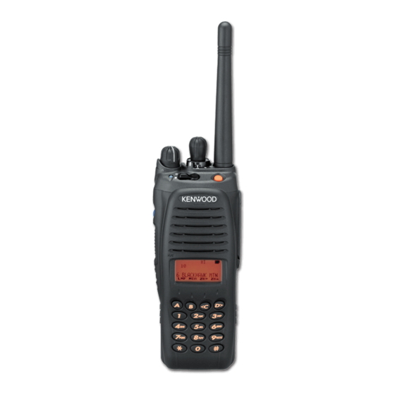
VHF P25 TRANSCEIVER
TK-5210
SERVICE MANUAL
TK-5210(G) K
Knob (Selector)
(K29-9323-03)
Knob (Volume)
(K29-9322-03)
Knob (PTT)
(K29-9328-02)
Main cabinet
(A02-3875-01)
Does not come with antenna. Antenna is available as an option.
GENERAL .............................................................................2
SYSTEM SET-UP .................................................................3
REALIGNMENT ...................................................................4
INSTALLATION ..................................................................11
DISASSEMBLY FOR REPAIR ............................................12
CIRCUIT DESCRIPTION ..................................................18
COMPONENTS DESCRIPTION .........................................26
PARTS LIST .......................................................................28
EXPLODED VIEW ..............................................................40
PACKING ............................................................................42
TROUBLE SHOOTING ......................................................43
ADJUSTMENT .................................................................45
TERMINAL FUNCTION ....................................................66
This product complies with the
G
(
)
TK-5210(G) K2, K7
Knob (Selector)
(K29-9323-03)
Helical Antenna
(KRA-22: Option)
Knob (Volume)
(K29-9322-03)
Key top
(EMG)
(K29-9319-03)
Knob (PTT)
(K29-9328-02)
Main cabinet
(4key)
(A02-3877-11)
CONTENTS
directive for the European market.
RoHS
© 2010-7 PRINTED IN JA PAN
B51-8910-10 ( N )
As for the hardware of this transceiver, version 3 is used.
The programming software must use KPG-95DG.
TK-5210(G) K3
Knob (Selector)
(K29-9323-03)
Helical Antenna
(KRA-22: Option)
Knob (Volume)
(K29-9322-03)
Key top
(EMG)
(K29-9319-03)
Knob (PTT)
(K29-9328-02)
Key top
(4key)
(K29-9320-03)
Main cabinet
(DTMF)
(A02-3879-11)
PC BOARD
CONTROL UNIT (X53-4390-XX) .................................74
TX-RX UNIT (X57-7650-10) .........................................78
INTERCONNECTION DIAGRAM ......................................82
SCHEMATIC DIAGRAM ...................................................84
BLOCK DIAGRAM ............................................................96
LEVEL DIAGRAM ...........................................................100
KNB-32N (Ni-MH Battery Pack) ...............................101
KNB-33L (Li-ion Battery Pack)..................................101
KNB-54N (Ni-MH Battery Pack) ...............................101
KSC-32 (Rapid Charger) ............................................101
KBP-6 (Battery Case) ................................................101
SPECIFICATIONS ..........................................BACK COVER
Helical Antenna
(KRA-22: Option)
Key top
(EMG)
(K29-9319-03)
Key top
(DTMF)
(K29-9321-13)
This product uses Lead Free solder.
Advertisement
Table of Contents


Need help?
Do you have a question about the TK-5210G and is the answer not in the manual?
Questions and answers