Table of Contents
Advertisement
TABLE OF CONTENTS
1. INTRODUCTION..................................................................................................
2. SAFETY PRECAUTIONS.....................................................................................
3. LIST OF PARTS...................................................................................................
STEP 0 Preparation: Inspect Walk Belt Placement............................................
STEP 1 Assemble the Left and Right Pedestals and Handlebars......................
STEP 2 Install the Display..................................................................................
STEP 3 How to Move the Treadmill...................................................................
STEP 4 Level the Unit........................................................................................
STEP 5 Align the Walk Belt................................................................................
STEP 6 Adjust Walk Belt Tightness....................................................................
STEP 7 Install the Power Cord...........................................................................
DISPLAY Overview................................................................................................
DISPLAY Specifications........................................................................................
DISPLAY Windows................................................................................................
DISPLAY Keys......................................................................................................
DISPLAY Safety Key.............................................................................................
6. OPERATE THE T655 TREADMILL.......................................................................
OPERATION Quick Start Key................................................................................
OPERATION Start a Workout Program.................................................................
OPERATION During the Workout..........................................................................
OPERATION Cool Down.......................................................................................
OPERATION Review Summary.............................................................................
OPERATION IDLE Mode.......................................................................................
OPERATION Energy Smart Function....................................................................
OPERATION Workout Programs...........................................................................
OPERATION User Preferences and Component Versions....................................
OPERATION Error Messages................................................................................
7. ABOUT HEART RATE DETECTION AND PRESENTATION
HEART RATE Telemetry.......................................................................................
HEART RATE Contact..........................................................................................
HOW HARD SHOULD I EXERCISE?...................................................................
HOW LONG SHOULD I EXERCISE?...................................................................
HOW OFTEN SHOULD I EXERCISE?.................................................................
9. ACCESSORIES.....................................................................................................
MAINTENANCE How to Replace a Fuse.............................................................
MAINTENANCE Lubrication System....................................................................
MAINTENANCE Schedule....................................................................................
MAINTENANCE Task List.....................................................................................
MAINTENANCE One-Year Maintenance Log.......................................................
MAINTENANCE Electronics Block Diagram.........................................................
SPORTSART T655 TREADMILL
1
2
8
10
11
20
23
24
25
26
27
28
29
29
29
32
33
33
33
34
35
35
35
35
36
42
43
44
44
46
46
46
47
49
50
53
54
56
57
Advertisement
Table of Contents

Related Manuals for SportsArt Fitness T655


Summary of Contents for SportsArt Fitness T655
-
Page 1: Table Of Contents
STEP 3 How to Move the Treadmill..............STEP 4 Level the Unit..................STEP 5 Align the Walk Belt................STEP 6 Adjust Walk Belt Tightness..............STEP 7 Install the Power Cord................5. UNDERSTANDING THE T655 DISPLAY DISPLAY Overview....................DISPLAY Specifications..................DISPLAY Windows....................DISPLAY Keys...................... -
Page 2: Introduction
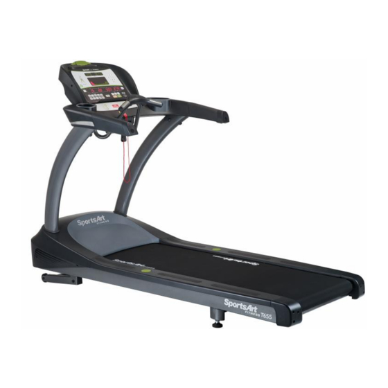
1. INTRODUCTION Congratulations on the purchase of a high quality SportsArt product, the T655 treadmill. Constructed of high quality materials and designed for years of reliable performance, this product was made for full commercial use. Before this product is assembled or operated, we recommend that you familiarize yourself with this manual. -
Page 3: Safety Precautions
2. SAFETY PRECAUTIONS .This product was designed and built for optimum safety. However certain precautions apply during the use of this product. Please note the following safety precautions: .Please read the entire manual before assembly and operation. Make sure the product is installed and operated as instructed in this manual. - Page 4 2. SAFETY PRECAUTIONS (CONTINUED) . Children should be supervised to ensure that they do not play on or near the product. .Treadmills should be positioned away from walls to avoid injury due to falls. Be sure that the back of the treadmill has at least six to seven feet of clearance from a ledge, wall or window.
- Page 5 2. SAFETY PRECAUTIONS (CONTINUED) .Do not stand on the walk belt when starting the treadmill. Straddle the belt with your feet on the right and left landing strips. .Always use the safety key when operating the treadmill. .French speakers, please note the following: .Please place the sticker (provided in the owner's manual) on the product as shown.
- Page 6 2. CONSIGNES DE SÉCURITÉ IMPORTANTES Votre tapis de course SportsArt a été conçu et fabriqué afin d'assurer une sécurité optimale. Cependant certaines précautions s'appliquent chaque fois que vous utilisez votre tapis de course. .Lisez entièrement le manuel avant l'assemblage et l'utilisation. Veuillez aussi noter les consignes de sécurité...
- Page 7 CONSIGNES DE SÉCURITÉ (SUITE) . Maintenez le cordon éloigné de toute surface chaude. .Veillez à ce qu'aucun orifce de ventilation ne soit obstrué. .Ne faites jamais tomber ou n'insérez jamais d'objet dans les orifces. .NE PAS l'utiliser là où des produits aérosols (vaporisés) sont utilisés ou lorsque de l'oxygène est administré.
- Page 8 CONSIGNES DE SÉCURITÉ (SUITE) . Utilisez toujours le clip de sûreté pendant le fonctionnement du tapis de course. . NE PAS rester sur le tapis de marche lors du démarrage du tapis de course. .. . Enjambez le tapis et placez vos pieds sur les bandes de repos droite et gauche. ...
-
Page 9: List Of Parts
3. LIST OF PARTS Assembly Parts Name Qty No. Description Display Left pedestal Handlebar assembly Front handlebar assembly Right pedestal Owner manual Feeder cord Hardware kit Waterproof ring Power cord Main frame Right side cover Left side cover... - Page 10 (Continued) 3. LIST OF PARTS Components in the Hardware Kit Name Name Specification Specification Notes Notes Screw cover (flat) Screw cover (rounded) 15A-100V~110V Fuse 10A-200V-240V 25A-100V~110V T-shaped Allen wrench (M4) T-shaped Allen wrench (M6) L-shaped Allen wrench (M5) L-shaped Allen wrench (M6) Double open-end wrench (22*24)
-
Page 11: Assembling The Product
4. ASSEMBLE THE PRODUCT Follow instructions below to assemble this product. Note that in this manual the words “left” and “right” are used to refer to the product and its parts. As such, these designations correspond to the “left” and “right” sides of a person in position to exercise on this product. -
Page 12: Step 1 Assemble The Left And Right Pedestals And Handlebars
STEP 1 Assemble the Left and Right Pedestals and Handlebars Follow instructions below to install the pedestals and handlebar assembly. The illustration below provides an overview of this step. -11-... - Page 13 Assemble the Left and Right Pedestals and Handlebars (Continued) STEP 1 (a) Loosen and remove the screws (40) to remove the pedestal mount covers (A6a, A6b) as shown. (b) Remove the screws (41) from the pedestal mount as shown. -12-...
- Page 14 Assemble the Left and Right Pedestals and Handlebars (Continued) STEP 1 Follow steps (a~e) in order to thread the data cable into the right pedestal. (a) First, remove the zip tie on the cable in the right pedestal mount, and then stretch the cable out as shown.
- Page 15 Assemble the Left and Right Pedestals and Handlebars (Continued) STEP 1 Hold the data cable at the top of the right pedestal (A3), and insert the bottom of the pedestal onto the pedestal mount. Avoid pinching or crimping the data cable. Place the water guard (A6) on the pedestal higher than the motor cover.
- Page 16 Assemble the Left and Right Pedestals and Handlebars (Continued) STEP 1 Follow steps (a~f) to install handlebars. (a) First, remove the screws (42, 43) from the handlebar assembly (A2). (b) Insert the left side of the handlebar (A2) into the left pedestal (A7). (c) Connect the cables in area A from the right pedestal (A3) and from the handlebar (A2).
- Page 17 Assemble the Left and Right Pedestals and Handlebars (Continued) STEP 1 (d) Tuck cables into the pedestal safely, and then insert the right side of the handlebar assembly (A2) into the right pedestal (A3), without pinching or crimping cables. (e) Thread screws in place by hand. First, secure the screws (42) in area B, and then secure the screws (43) in area C.
- Page 18 Assemble the Left and Right Pedestals and Handlebars (Continued) STEP 1 Install the front handlebar assembly (a) Loosen and remove the screws (47) from the front handlebar assembly (A8). (b) Loosen the screws (46) from the front handlebar assembly (A8). Do not remove the screws.
- Page 19 Assemble the Left and Right Pedestals and Handlebars (Continued) STEP 1 (c) Connect the cables from the front handlebar assembly (A8) and from the handlebar assembly (A2). (d) Insert the front handlebar assembly (A8) into the handlebar assembly (A2) and secure with the screws (47) (46).
- Page 20 Assemble the Left and Right Pedestals and Handlebars (Continued) STEP 1 After the handlebars are in place, secure pedestal screws on left and right sides. Put the pedestal covers (A6a, A6b) in place, and then put the water guards (A5) down against the motor cover on both sides.
-
Page 21: Step 2 Install The Display
STEP 2 Install the Display -20-... - Page 22 STEP 2 Install the Display (Continued) Follow steps (a~f) below to install the display assembly. (a) Remove the screws (44) from the handlebar (A2). (b) Insert the display (A1) onto the handlebar assembly (A2). (Note: aim properly to avoid damaging the display board.) (c) Then slightly lift the display (A1).
- Page 23 STEP 2 Install the Display (Continued) (d) Connect cables in areas A and B. (e) After connecting cables, tuck them away for safety, and then slightly lift the display (A1) and press it into place. (Note: In area C, the display cover must be outside of the handlebar cover.) (f) Use the screws (44) to secure the display (A1) in place.
-
Page 24: Step 3 How To Move The Treadmill
STEP 3 How to Move the Treadmill First, place hands under the frame in area A, lift the treadmill, then roll it into position as desired. -23-... -
Page 25: Step 4 Level The Unit
STEP 4 Level the Unit 1. Press on points A and B to inspect whether the unit is stable and level on the ground. 2. If not, please level the treadmill by following instructions (a, b, c): (a) First, loosen the leveler nuts. (b) Adjust the leveler feet downward until the treadmill is level and does not rock. -
Page 26: Step 5 Align The Walk Belt
STEP 5 Align the Walk Belt (a) First, make sure the treadmill is on a leveled surface and the incline is at 0%. (b) Start the speed at a lower rate of 3kph/2.5mph to check if the walk belt is aligned and there is an equal amount of space between walk belt and side-rails on both sides. -
Page 27: Step 6 Adjust Walk Belt Tightness
STEP 6 Adjust Walk Belt Tightness As you exercise, does the walk belt suddenly pause and then regain traction? Or, if you bear down against the walk belt, does the belt not pause whatsoever? If either of these two conditions occurs, the walk belt may be too loose or too tight. In this case, please turn off the treadmill and adjust walk belt tightness. -
Page 28: Step 7 Install The Power Cord
STEP 7 Install the Power Cord (a)First remove screws (45) from the power cord socket on the product. (b) Insert the power cord into place on the product. (c) Secure power cord connector screws (45). Then insert the other end of the power cord (A11) into the appropriate power supply socket in the wall. -
Page 29: Understanding The T655 Display
5. UNDERSTANDING THE T655 DISPLAY DISPLAY Overiew The T655 display was designed to help people obtain their fitness goals simply and conveniently. Please familiarize yourself with the features of this display and thereby get optimum benefit and enjoyment from this product. -
Page 30: Display Specifications
DISPLAY Specifications 1.SPEED: 0.1 ~ 15.0 MPH or 0.2 ~ 24.0 KPH. 2.INCLINE: -3% ~ 15%, in increments of 0.5% 3.TIME: 0 ~ 300 4.DISTANCE: 0.00 ~ 9999 Km/Mile 5.CALORIES: 0 ~ 9999 K-CAL 6.Calories burnt per hour: 0 ~ 9999 kcal 7.METS (metabolic equivalency of task): 0.0 ~ 99.0 8.PACE: 1 / SPEED 9.PROGRAM: MANUAL, HILL (HILL1, HILL2, HILL3), RANDOM, INTERVAL... - Page 31 DISPLAY Keys (Continued) ENTER Press the ENTER key to confirm your selections. MANUAL Press the MANUAL key to directly control incline and speed. HILL Each time this key is pressed, the LED above the key will light and one of three hill workouts will appear: HILL 1, HILL 2, HILL 3.
- Page 32 DISPLAY Keys (Continued) Numeric keys 0 to 9 When establishing settings, you can directly press numeric keys rather than ▲/▼ keys. While exercising, numeric keys also allow you to directly set the speed value. CLEAR Press the CLEAR key to clear information when setting up a workout program. INCLINE ▲/▼...
-
Page 33: Display Safety Key
DISPLAY Safety Key This safety key must be in place for the treadmill to operate. This safety device is intended to stop the treadmill should a user stumble and fall. When the safety key is not in place, the message “SAFETY KEY” appears as a reminder to put the safety key in its proper place. -
Page 34: Operate The T655 Treadmill
6. OPERATE THE T655 TREADMILL Your SportsArt Fitness treadmill has many outstanding electronic features that can help you get the most out of your workout. By thoroughly understanding the display functions, you can greatly improve your workout experience. Please read the following instructions to begin your workout. -
Page 35: Operation During The Workout
OPERATION Start a Workout Program (Continued) ˙The CALORIE setting range is from 100 to 9999 k-Cal, with a default value of 100 k- Cal. Use▲/▼keys or numeric keys (0-9) to make your selection. Press the ENTER key to confirm your setting and proceed to the age setting. Or press the QUICK START key to start this program right away with default age and weight. -
Page 36: Operation Cool Down
Orange to Red and so forth. 2. The following message will appear on the exercise feedback window repeated,” WELCOME TO SPORTSART FITNESS. THE LEADING FITNESS EQUIPMENT COMPANY IN THE WORLD. OUR MISSION STATEMENT. TO UTILIZE INNOVATION, UNIQUE DESIGN AND MANUFACTURING EXCELLENCE TO CREATE PRODUCTS OF EXCEPTIONAL QUALITY AND PERFORMANCE THAT WILL ENHANCE HEALTH, WELLNESS AND LIFESTYLE FOR YEARS TO COME. -
Page 37: Operation Workout Programs
OPERATION Workout Programs The following explains features of the workout programs. MANUAL The MANUAL program allows direct control of speed and incline functions. HILL There are three hill workout courses. Press the HILL key repeatedly to toggle through the three courses. When your preferred workout course appears, press the ENTER key to confirm your choice. - Page 38 OPERATION Workout Programs (Continued) FAT BURN The FAT BURN program has twenty stages to choose from (Default value: LEVEL 1). Each stage corresponds to a different pattem of incline levels. 1. “LEVEL - XX” will appear on the message window. 2.
- Page 39 OPERATION Workout Programs (Continued) a. The user presses the STOP key. b. The fitness test comes to completion. c. The user's heart rate exceeds (220 AGE) * 0 85 for more than 15 seconds. d. There is no heart rate signal continuously for 30 seconds. At this point, the message screen shows “TEST END - xx MIN”, where xx represents the rest time period.
- Page 40 OPERATION Workout Programs (Continued) .Gender a. A gender prompt, M/F, will appear. b. Press SPEED ▲/▼ keys and INCLINE ▲/▼ keys to select your gender. c. Press the ENTER key to confirm the setting and proceed to select either the walking or the running test.
- Page 41 OPERATION Workout Programs (Continued) WT LOSS or CARDIO These programs employ what is called Heart Rate Control (HRC) technology to adjust speed or incline to maintain a specific target heart rate. Heart rate control programs are designed to provide optimal efficiency in reaching your exercise goals. 1.
- Page 42 dot matrix screen. When the actual heart rate signal is detected, the color of the heart illustration will alternate between red and green. Otherwise, it will maintain with green color. Orange color represents the 65% or 80% of max HR or target heart rate entered.
-
Page 43: Operation User Preferences And Component Versions
OPERATION User Preferences and Component Versions Basic settings determine units of measure and show total distance and time, along with display and drive board program version numbers. To access this information, at the startup banner screen, hold the CHANGE DISPLAY key for two seconds. UNITS The display will show “UNIT –... -
Page 44: Operation Error Messages
DRIVE BOARD PROGRAM VERSION The drive board program version will appear as “DRV SERVO - XX”, where XX represents either a letter or a number. Press the ENTER key to finish the review and return to Banner mode. You may press and hold the STOP key at anytime during this process to resent the console and back to Banner state. -
Page 45: Heart Rate Telemetry
7. ABOUT HEART RATE DETECTION Heart rate detection functions are optional and may not be included in your particular model. If your bike is equipped with these functions, please note the following information. HEART RATE Telemetry The word "telemetry heart rate" refers to the detection of the heart rate, usually via a strap worn on the exerciser's chest, and transmitted over the air for reception by a receiver built into the product. - Page 46 HEART RATE Contact (Continued) 3. It is difficult to detect the heart rate of people with dry, course palms. Keeping palms smooth and damp improves heart rate detection. 4. The vibration of treadmills at speeds over 4mph/6.4kph makes heart rate detection difficult.
-
Page 47: Guidelines For Exercise
8. GUIDELINES FOR EXERCISE HOW HARD SHOULD I EXERCISE? Studies show that to achieve the benefits of aerobic exercise, it is necessary to work within your training zone. Your training zone depends on your age and level of fitness. The above chart indicates the recommended Heart Rate training zones (darkened area of the chart). -
Page 48: Accessories
9. ACCESSORIES There are accessories attached to this console; some are standard and some are optional. The following explains the details of each accessory and its function. USB Charger (Standard) The USB charger will provide 5V 500mA voltage for the smart phone or other devices charging. - Page 49 (CONTINUED) 9. ACCESSORIES Entertainment Cap : (a) RFID member card slot: work with both optional SAFitDirector and ECOFIT member cards. (b) Bluetooth connection button: press this button to pair or unpair the smart phone SAFitDirector App. (c) USB port: this port is used for device charging as well as optional data transferring. (d) USB port: this port is used for device charging.
-
Page 50: Maintenance
10. MAINTENANCE This section covers maintenance topics, including instructions on replacing a fuse and lubricating the walk belt, along with the presentation of a maintenance schedule, maintenance task list, one-year maintenance log, and electronics block diagram. MAINTENANCE How to Replace a Fuse If electrical current becomes too high, the fuse breaks. -
Page 51: Maintenance Lubrication System
MAINTENANCE Lubrication System Lubrication System Flowchart Lubricant Change Procedure Note: Pay extra attention during the lubricant changing procedure to avoid electric shock; especially operating it while the power is on. -50-... - Page 52 MAINTENANCE Lubrication System (Continued) To replace the lubricant bottle, follow instructions (a) through (d) below. (a) Loosen the screws on the bezel and push the bezel up. (b) Take the old lubricant bottle out. Unscrew the nozzle from the old lubricant bottle and screw it onto new bottle. (d) Place the new lubricant bottle into the lubrication system;...
-
Page 53: Error Messages
MAINTENANCE Lubrication System (Continued) Error Messages: There are 2 error messages with this system. Error 1: It indicates that the system memory failing and it will not be able to perform any auto lubrication. <Err. 01> <EEPROM> Error 2: It indicates motor is failing or system will not be able to perform any function. <Err. -
Page 54: Maintenance Schedule
MAINTENANCE Schedule (T655) Maintenance Schedule Area Day Week Month Quarter Year Notes Exterior Clean. Screws Inspect and secure loose parts. Ensure the treadmill operates Treadmill test properly. Inspect alignment (centering) Walk belt and look for wear. Inspect for wear. Walk deck Inspect for normal rotation. -
Page 55: Maintenance Task List
MAINTENANCE Task List Like cars, fitness products require maintenance. Regular maintenance extends product life, and failure to maintain products can void the manufacturer's warranty. Copy the maintenance log sheet, and record maintenance work for each fitness product. Daily tasks 1. Use a clean, lint-free towel, dampened with a mixture of Simple Green® all-purpose cleaner and water, to thoroughly clean the product exterior. - Page 56 MAINTENANCE Task List (Continued) Caution Please follow standard safety precautions when serving on this product. .Electronic components can carry an electrical charge even after the product has been turned off. For safety, turn off unit power. Wait five minutes to allow capacitors to discharge, and then disconnect the power cord from the wall socket (if applicable.) Only after such steps have been completed should covers be removed and electronic components accessed.
-
Page 57: Maintenance One-Year Maintenance Log
MAINTENANCE One-Year Maintenance Log Facility : Supervisor: Product Model Number : Serial Number: Start Date: End Date: Daily Tasks Weeks 8-14 Weeks 1-7 Weeks 15-21 Weeks 22-28 Completed Daily Tasks Weeks 29-35 Weeks 36-42 Weeks 43-49 Weeks 50-52 Completed Weekly Tasks Weeks 1-7 Weeks 8-14 Weeks 15-21... -
Page 58: Maintenance Electronics Block Diagram
MAINTENANCE Electronics Block Diagram Your Authorized Distributor -57-...
Need help?
Do you have a question about the T655 and is the answer not in the manual?
Questions and answers