Table of Contents
Advertisement
Advertisement
Table of Contents

Subscribe to Our Youtube Channel
Related Manuals for Hobbico Superstar 60


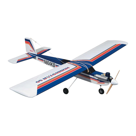
Summary of Contents for Hobbico Superstar 60
- Page 1 Easy as 1, 2, 3 Entire Contents © Copyright, 2001 HCAZ3090 V 1.1...
-
Page 2: Tail Assembly
Part # Quantity Horizontal Stab and elevator ..1 ers, Hobbico’s SuperStar series offers nearly all the Vertical fin and rudder....1 excitement of piloting a real airplane...and develops 25 Clevises ..........5 skills that will take you anywhere you want in your 26 Control horns .........2... - Page 3 43 35 Engine Mounting Parts Fuel Tank & Parts Part # Quantity Part # Quantity 35 Adjustable engine mount....2 12 Fuel tank ..........1 43 6-32 x 7/8” Machine screw....4 13 Tank stopper........1 44 #6 x 5/8” Sheet Metal Screw....4 14 Fuel pick-up weight ......1 50 Push rods and guide tubes....2 15 Plastic stopper compression disks (one large and one small) ....2...
-
Page 4: Radio Equipment
Getting Ready for Flight Your Hobbico SuperStar trainer is ready for takeoff in as little as 20 hours. Your hobby dealer or flying instructor (see next page) can help you decide what accessories you’ll need for flight. Most are one-time only purchases—and your instructor will probably allow you to use his field box until you can outfit your own with a glow plug starter, fuel pump, and “chicken stick"... -
Page 5: Before You Fly
If you, as the original owner of this model, discover defects in parts or as possible. workmanship within 90 days of purchase, Hobbico will repair or replace 1. ALWAYS return your entire system, including airplane and radio. it—at the option of our authorized U.S. repair facility, Hobby Services—... -
Page 6: Assembling The Wing
Assembling the Wing Special Note: even coat of epoxy on both sides of one of the wing joiners. Sandwich this coated joiner between the You should charge your radio system before starting remaining two. Quickly proceed through the to build. Following the manufacturer’s directions, following steps (3 and 4) before the glue cures. - Page 7 Mark the centerline on the joiner Trial fit the wing joiner Balsa Aileron Servo Tray Block (2) ❏ 8. Trial fit the wing joiner in both wings by sliding Actual Size the joiner into the joiner cavity in the wing. The joiner ❏...
-
Page 8: Join The Wing Halves
Glue the joiner into the wing the two wing halves. Clean the excess epoxy from the outside of the wing using a paper towel dampened with rubbing alcohol. Tape the wing halves together ❏ 11. Mix 1/4oz. (7.5ml) of 30-minute epoxy to glue the joiner into one wing half. -
Page 9: Install The Servo Tray
Remove the covering Trial fitting the aileron servo ❏ 16. Hold the servo tray over the hole. Trace the outside of the tray with a felt-tip pen and then remove the tray from the wing. Draw two lines 3/8” from the ends as shown. -
Page 10: Install The Aileron Control Horns
Apply the center tape Install the aileron control horns Aileron Control Horn (2) Actual Size ❏ 21. Starting at the front of the aileron servo tray, apply the 1/2" (12.5mm) white plastic center tape ❏ 23. Thread the white aileron control horns onto the completely around the wing over the joint. -
Page 11: Install The Pushrods
Install the pushrods NOTES ON WING ASSEMBLY ❏ 25. Attach the control rods to the aileron control horns. Press the forks of the clevis together until they snap into place. Aileron pushrods installed ❏ 26. Locate the 1/4" (6.5mm) diameter clear retaining tube and cut two 1/4"... -
Page 12: Fuselage Assembly
Fuselage Assembly Locate the wing dowel holes Locate the stab slot ❏ 3. Locate the horizontal stabilizer slot under the covering on the tail section of the fuselage by pressing lightly with your finger. The slot will be located on ❏... - Page 13 Remove the tail post Check the rudder and elevator hinges ❏ 8. Gently tug on the rudder and elevator at each hinge location. If any of the hinges are loose, reglue them as described here: First, flex the surface all the ❏...
-
Page 14: Install The Stabilizer
Align the stabilizer with the fuse from the center. Do not cut the wood under the covering! This would seriously weaken the stab and could easily cause the stab to break in flight. If the stab breaks the plane may crash, so be very careful when you make this cut. - Page 15 Locations of the control horns into each hole. This will add strength to the balsa. Redrill the holes to remove any excess glue. Insert two 2 x 20mm machine screws through the control horn, Rudder Control horn rudder and finally screwing them into the control horn back plate on the opposite side of the rudder.
- Page 16 Cut the elevator exit hole holes using a 13/64” drill bit. Next, bevel the inside corners of the holes so that the bend in the wire will seat fully into the holes. Install the landing gear struts ❏ 21. The precut elevator pushrod exit hole is located on the same side of the fuselage as the elevator control horn.
- Page 17 31. Make a Z-bend at one end of both of the 1/16” x screws completely at this time. 19-3/4” wire throttle and steering pushrods. NOTE: Hobbico offers pliers that easily make perfect Install the throttle guide tube Z-bends (HCAR2000) see your hobby dealer.
- Page 18 Install the nose gear strut aluminum tube will not be used.) Place the two white plastic discs over the tubes. The larger disc should go towards the outside. The nub on the small disc should face away from the rubber stopper. Insert the 3 x 18mm self tapping screw through the larger disc, rubber plug and then into the smaller disc.
-
Page 19: Install The Tank
side. Tighten the stopper by turning the self tapping the engine and tighten the four screws to secure the screw. Do not over-tighten the screw or you may strip mount to the firewall. out the plastic disc. Align the engine with the fuselage Install the foam collar and bend the tubes ❏... -
Page 20: Mount The Engine
Mount the engine to shorten the fuel lines for a more direct routing. Make sure that the lines do not get any kinks which could restrict fuel flow. Attach the propeller to the engine ❏ 48. Slide the throttle pushrod wire into the guide tube and position the engine on the mount. -
Page 21: Install The Servos In The Fuselage
Trial fit the servos Install the servos in the fuselage ❏ 54. Trial fit your servos into the plywood servo tray. Enlarge the servo tray opening, if needed, using a flat file. The servo should fit easily into the radio tray. ❏... -
Page 22: Receiver And Battery Installation
Receiver and battery installation Prepare the pushrods ❏ 59. Following the radio system’s instruction manual, plug the three servos into the receiver. Next, plug a servo extension into the aileron channel (usually channel one) of the receiver. Finally, plug the switch into the receiver. -
Page 23: Connect The Pushrods
Attach the pushrods Cut the pushrods ❏ 65. Attach the two clevises to the control horns. Use the 2nd hole from the outside. Check to make certain that the pushrods do not bind in the openings and that they operate smoothly. Slide the clevis ❏... - Page 24 place, thread the 3mm x 4mm screw into to cause the aileron to travel further up than down, the connector. which is known as “differential aileron throw.” This will give smoother banking control Install the steering pushrod and will reduce the airplanes adverse yaw tendency (typical with flat bottom wings).
-
Page 25: Install The Wheels
Install the wheels Notes on Fuselage assembly: ❏ 76. Place one wheel collar on each strut, followed by a wheel. Secure each wheel with an additional wheel collar, making a total of two on each strut--one on the inside and one on the outside of the wheel. The nose gear wire is thinner, so use the wheel with the smaller center hole along with the two remaining small wheel collars. -
Page 26: Radio System Set-Up
Radio System Set-Up 1. Turn on the Transmitter and then the Receiver. stop fully open at the same time the throttle stick Standing behind the plane, make the following reaches full. With the throttle set up properly, you movements with the transmitter and observe the should be able to start and run the engine with the control surfaces: trim lever set midway to full position (adjusted for a... -
Page 27: Balance Your Model
Balance Your Model 1. Check the lateral balance. With the wing attached, “nose heavy” and you must add weight to the tail. If gently lift the airplane by the spinner and the bottom possible, first attempt to balance the model by center of the tail. - Page 28 There is one thing that you will need to fly your your area and join. Club fields are set up for R/C flying SuperStar 60 safely that is not furnished with the kit: which makes your outing safer and more enjoyable.
-
Page 29: Engine Safety Precautions
ENGINE SAFETY PRECAUTIONS without notifying the airport operator. I will give right-of-way and avoid flying in the proximity of full- NOTE: Failure to follow these safety precautions may scale aircraft. Where necessary, an observer shall be result in severe injury to yourself and others. utilized to supervise flying to avoid having models fly in the proximity of full-scale aircraft. -
Page 30: Ground Handling
Start with learning to steer the model on the ground using the rudder and Thank you for choosing the SuperStar 60. We hope throttle. You should learn to guide the airplane on the that it will be only the first of many, in a lifetime Be careful–... -
Page 31: Glossary Of Terms
Glossary of Terms Yaw Axis Wing Tip Aileron Pitch Axis Hinges Vertical Fin Roll Axis Trailing Edge Aileron Rudder Leading Torque Rods Control Horns Edge Hinges (on all control Propeller surfaces) Engine Muffler Fuel Tank Elevator Stabilizer Servos Fuselage Pushrods Receiver Battery Spinner Receiver... - Page 32 Dihedral – The V shaped bend Flaps – Hinged control surface atmospheric pressure or attaches in the wing. Typically more located at the trailing edge of the to the muffler pressure nipple, to dihedral causes more aerody- wing inboard of the ailerons. pressurize the fuel tank for bet- namic stability in an airplane, The flaps are lowered to produce...
- Page 33 Horizontal Stabilizer – The hor- Nitro – NitroMethane, a fuel radio in the airplane perceives izontal tail surface at the back additive which increases a commands from the transmit- of the fuselage which provides model airplanes’ ability to idle ter and the radio in your car aerodynamic pitch stability and low and improves high speed perceives music from the radio...
- Page 34 connects to the pushrod. Transmitter (Tx) – The hand ity. This is the surface the held radio controller.This is the rudder attaches to. Spinner – The nose cone which unit that sends out the com- covers the hub of the propeller. mands that you input.
-
Page 35: Building Notes
BUILDING NOTES Kit Purchase Date Date Construction Finished Where Purchased Finished Weight Date Construction Started Date of First Flight Flight Log... - Page 36 Ask for these fine Hobbico accessories at your favorite hobby retailer. HCAP0800 HCAP2520 HCAP2503 TorqMaster LC 12 Volt Battery Hot Shot II Standard Twist/Lock Glow Plug Clip HCAP3105 Top Fueler MKII HCAP2550 HCAP3015 4-Way Wrench Hand Crank Fuel Pump HCAQ2020 #64 Rubber Bands 1/4 lb.
Need help?
Do you have a question about the Superstar 60 and is the answer not in the manual?
Questions and answers