Table of Contents
Advertisement
Quick Links
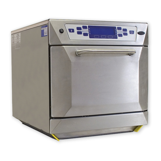
Merrychef
Version 3.0
Version 2.0
402s
S E R V I C E & P A R T S M A N U A L
This manual covers UK/EC models manufactured from:
ISSUE 4
Version 2.0 Serial No. 000745 –001199
01.05.2008
Version 3.0 Serial No. 001200 onwards
CAUTION MICROWAVE EMISSIONS
DO NOT BECOME EXPOSED TO EMISSIONS FROM THE MICROWAVE
GENERATOR OR PARTS CONDUCTING MICROWAVE ENERGY
o.
402s Ovens Part. N
32Z3539 Issue 4
1
Advertisement
Table of Contents

Related Manuals for Merrychef s


Summary of Contents for Merrychef s
- Page 1 Merrychef Version 3.0 Version 2.0 402s S E R V I C E & P A R T S M A N U A L This manual covers UK/EC models manufactured from: ISSUE 4 Version 2.0 Serial No. 000745 –001199 01.05.2008...
-
Page 2: Table Of Contents
Appendix 7: Electrical Installation Guide .......54 Merrychef Limited, Station Road West, Ash Vale, Aldershot Hampshire GU12 5XA United Kingdom Tel: +44 (0)1252 371000 Fax: +44 (0)1252 371007 Internet address: http://www.merrychef.com E-mail: sales@merrychef.com or service@merrychef.com 402s Ovens Part. N 32Z3539 Issue 4... -
Page 3: Safety Code
SAFETY CODE This manual is designed to assist engineers who have been on a recognised product familiarisation and training course run by Merrychef. It has been prepared to offer technical guidance for the 402s range of Ovens. Please remember that it is wiser not to attempt a service task if you are unsure of being able to complete it competently, quickly, and above all safely. -
Page 4: Product Specifications
Power Output Microwave 100% 1500watts Convection 3250watts External Height 595mm (23.0 inches) Dimensions Width 585mm (23.0 inches) Depth 700mm (27.5 inches) Weight Nett 90kg ( 198lb.s ) Construction Cavity 304 Stainless Steel Casework 402s Ovens Part. N 32Z3539 Issue 4... -
Page 5: Installation Instructions
INSTALLATION INSTRUCTIONS Installation Instructions for Mealstream 402s Ovens Power Supply Requirements The Mealstream 402s should be connected to a suitable electricity supply, which can cope with the switching-on surge that occurs with certain types of catering equipment, including microwaves. Because of this requirement, we strongly recommend that a separate, suitably rated supply is installed for the oven. -
Page 6: Main Features
MAIN FEATURES a On/Off SWITCH h DOOR This is used to turn the oven On or Off. The door consists of a thermally insulated inner section, and an additional air gap provided by a IT DOES NOT ISOLATE INTERNAL WIRING twin skinned door front to lower the surface FROM THE MAINS SUPPLY. -
Page 7: Main Features Control Panel Version 2.0
Display Panel error messages Message Condition Possible cause ERROR MAGNETRON 1 Magnetron 1 has overheated Blocked Air filter(s) Oven located near hot air sources Oven being used empty ERROR MAGNETRON 2 Magnetron 2 has overheated Cooling fan failure Magnetron failure ERROR MAGNETRON 1 &... -
Page 8: Main Features Control Panel Version 3.0
MAIN FEATURES Electronic control panel Version 3.0 MAIN DISPLAY PANEL MenuKey COOL DOWN FUNCTION FUNCTION FUNCTION CANCEL PADS PADS PADS MenuKey 2 DISPLAY PANEL The MenuKey System automatically changes all the Shows the principal functions of the oven. cooking programs with an electronic key and allows When cooking, the time remaining counts down. -
Page 9: Principal Components: Rhs
PRINCIPAL COMPONENTS: Right Side Description Part No. Cavity Overheat stat 30Z1024 Motor Start Capacitor 2µF ( Blue ) 30Z1298 Filter 16A (Threaded) 30Z1340 Air filter SA276 Stirrer motor Assembly SA288 Microswitch SW1 30Z1294 Microswitch SW2 Door Hinge Assembly RH SA202 Magnetron Cooling Fan 30Z1295 HV Capacitor 2500V 1.1 F ( 50HZ models ) -
Page 10: Principal Components: Lhs
PRINCIPAL COMPONENTS: Left Side Description Part No. Filter 16A (Threaded) 30Z1340 Air filter SA276 Stirrer motor Assembly SA288 Microswitch SW3 30Z1294 Microswitch SW4 Door Hinge Assembly LH SA203 Motor Controller 30Z1319 Thermistor Cavity 30Z1315 HV Capacitor 2500V 1.0 F ( 50Hz models ) 30Z1331 HV Capacitor 2500V 0.88 F ( 60Hz models ) 30Z1251... -
Page 11: Principal Components: Control Box
PRINCIPAL COMPONENTS: Control Box Principal components: POWER SUPPLY Description Part No. Fuse 10A HRC 30Z0217 Gold resistor ( 220R ) 30Z0235 Relay PCB Assembly 11K0004 Ribbon Cable 15way 11Z0298 Ribbon Cable 10way MenuKey 11M0117 Logic PCB Assembly Version 2.0 11K0002 Logic PCB Assembly Version 3.0 11K0012 Transformer LT (Low voltage) -
Page 12: Principal Components: Back View
PRINCIPAL COMPONENTS: Back view Description Part No. DV0606 Heater Element 220V 650W DV0607 Heater Element 240V 650W Magnetron (Toshiba) 30Z1349 Magnetron Thermistor Assembly SA234 Convection ( Hot Air ) Motor Assembly SA208 30Z1233 Transformer 208/220/240V 50Hz Transformer 208/220/240V 60Hz 30Z1230 HT Diode Assy PCB (Fibre Optic) 11H0364 HT Diode Assembly ( Non-optic) -
Page 13: Principal Components: Power Supply
PRINCIPAL COMPONENTS: Power Supply Electrical Supply: Single Phase Electrical Supply: Twin phase 2P+N+Earth N1 L1 L2 Description Part No. Filter 16A 30Z1340 Fuse 10A HRC 30Z0217 Cable Gland 31Z0500 Cable Gland Nut 31Z0499 Electrical Supply Lead Assembly Single Phase SA226 Electrical Supply Lead Assembly Twin Phase SA225 Terminal Block... -
Page 14: Principal Components: Cavity Parts & Kfc Accessories
PRINCIPAL COMPONENTS Cavity Stirrer glass Shown removed Description Part No. Stirrer (behind stirrer glass) SA291 Grease Filter ( 2 parts ) SA340 SA339 Stirrer Glass DV0492 Rack Support ( Not shown ) DV0114 Upper Impinger plate SA211 Rack DV0275 Lower Impinger plate SA266 * Parts 35 &... -
Page 15: Principal Components: External Panels & Parts
PRINCIPAL COMPONENTS External Parts Control Panel See page 16 Door Assembly Description Part No. Air Filter SA276 Top Panel DV0187 Rear Panel SA329 Side Panel LH DV0091 Door Skin DV0501 Door Handle 32Z1066 Door Inner SA331 Door Choke DV0168 Door Seal (wide) DV0305 Door seal sealant ( tube ) 31Z0186... -
Page 16: Principal Components: Electronic Control Panel Assembly
PRINCIPAL COMPONENTS Electronic Control Panel Assembly Version 2.0 Version 3.0 Description Part No. MenuKey Dust Cover DV0052 Power switch (On/Off) 30Z1318 GM Membrane Version 2.0 DV0055 Front Panel Version 2.0 DV0036 Display Assembly & Header Version 2.0 30Z1299 MenuKey Socket 11K0005 GM Membrane Version 3.0 DV0254... -
Page 17: Parts Matrix
Part number identification chart 1 Ref. No. Description Part No. Cavity High limit Stat 30Z1024 Motor Start Capacitor 2µF ( Blue ) 30Z1298 Filter 16A 30Z1340 Air filter SA276 Stirrer motor Assembly SA288 Stirrer (inside cavity) SA291 Microswitch SW1, SW2, SW3, SW4 30Z1294 Door Hinge Assembly RH SA202... - Page 18 Part number identification chart 2 Ref. Description Part No. Ref. Description Part No. Fuse Holder 30A 30Z1178 Oven tray MC3175 Fuse Holder 10A 30Z0231 Handle Assembly SA267 Grease Filter ( 2 parts ) SA339 Griddle DV0221 SA340 Stirrer Glass DV0492 Griddle carrier SA350 Rack Support...
-
Page 19: Procedure For Power Output Measurement
PROCEDURE FOR POWER OUTPUT MEASUREMENT The power output specification 1500W on this model is established under IEC 705 standard method. This method is only workable in Laboratory controlled conditions. An approximate method is as follows: Ensure the oven is cold before commencing the test Before this test is carried out the oven PREHEAT temperature must be set to 0ºC as this enables the oven to be used in Microwave ONLY mode. -
Page 20: Procedures For Principal Component Tests
PROCEDURES FOR PRINCIPAL COMPONENTS TEST (1) 1. Power Transformer Test You will need: A Digital Multi-meter (D.M.M.) A Megger or similar resistance meter using 500V d.c. WARNING: High voltages and large currents are present at the High Voltage Capacitor. It is very dangerous to work near this part when the oven is on. -
Page 21: High Voltage Rectifier Test
PROCEDURES FOR PRINCIPAL COMPONENTS TEST (2) ( High Voltage Capacitor Test continued, ensure steps 1-4 on previous page have been completed) Between Terminals Pass if approximately 10 M Between Terminals and Case Pass if open circuit 5. Using a Megger, test the insulation resistance between the terminals and the case. -
Page 22: Procedure For Door Interlock Adjustment
PROCEDURE FOR DOOR INTERLOCK ADJUSTMENT AND TEST 1 The door on the 402s oven is monitored by four microswitches. Three are used in the conventional “Primary, Secondary and Monitor” switch arrangement shown below and the fourth sends a signal to the Logic PCB. The switches operate as follows: Door Interlock Arrangement: Switches shown in Door Closed position Primary Secondary... -
Page 23: Procedure For Door Interlock Adjustment And Test
PROCEDURE FOR DOOR INTERLOCK ADJUSTMENT AND TEST 2 It is vital that the microswitches are adjusted to the correct position. There are two sets switch assemblies located either side of the oven. The interlocks ensure that the oven will not operate microwave with the door open. WARNING Before adjusting the microswitch assemblies ensure that the oven... -
Page 24: Hot Air Motor And Controller
PRINCIPAL COMPONENTS: Hot Air Motor & Controller 1 Convection and Fan Speed Control The convection heat is provided by 5 elements located in the hot box at the rear of the oven cavity. The hot air from the hot box passes over catalytic converters and is circulated into the bottom and top of the cavity through the impinger plates. - Page 25 PRINCIPAL COMPONENTS: Hot Air Motor & Controller 2 Motor Controller Provides an AC, 3-phase switched mode drive to the convection motor and is controlled by a 0 - 10 Volt signal from the logic board. This allows the motor to be adjusted from approximately 1500 rpm to 7000 rpm in steps of 5%.
-
Page 26: Circuit Diagram
402s Ovens Part. N 32Z3539 Issue 4... - Page 27 402s Ovens Part. N 32Z3539 Issue 4...
- Page 28 402s Ovens Part. N 32Z3539 Issue 4...
- Page 29 402s Ovens Part. N 32Z3539 Issue 4...
- Page 30 402s Ovens Part. N 32Z3539 Issue 4...
- Page 31 402s Ovens Part. N 32Z3539 Issue 4...
- Page 32 402s Ovens Part. N 32Z3539 Issue 4...
- Page 33 402s Ovens Part. N 32Z3539 Issue 4...
-
Page 34: Troubleshooting Guide
Trouble-Shooting Guide Is the problem Food Quality or Fundamental Operational Issue? Food Quality Fundamental Standard Food Quality Checks Standard Electrical Checks Check that the PREHEAT temperature is Check that oven is connected to an set correctly. Electricl Power supply and that any trip See User Manual. - Page 35 1.0 No Display Is Logic PCB Active ? See D7 LED Check cable from logic PCB to display is in place and no obvious wires are disconnected or shorted. Is Relay PCB Active see D27 Still Have a problem? Check 15 Way Ribbon Using spare display Cable between connect to Logic PCB...
- Page 36 5 Amps 5 Amps Check that the stirrer is rotating. Carry out Microwave Output Test Replace stirrer motor and retest Check Microwave Generating system Contact Merrychef Service Department for Further assistance. Transformer Magnetron Capacitor Diode 402s Ovens Part. N 32Z3539 Issue 4...
- Page 37 3.0 Cavity Sensor Error Report to Are there any Signs of Management and Cavity Fire Make Investigation Replace Sensor Check Temperature Retest Sensor Resistance Re-Start Oven Activate Pre-heat Yes LED is on. Is Led D19 on relay PCB ON Check Heater Elements Replace if necessary LED is on...
- Page 38 4.0 Magnetron / Overheat issues Remove and Clean Air Filters. If Dirty—Advise operating staff of the need for this to be carried out on regular basis. See User Manual Still have a problem. Check Location of oven is away from any major heat sources.
-
Page 39: Appendix 1: Temperature Sensor Resistance Data
APPENDIX 1: TEMPERATURE SENSOR RESISTANCE DATA Temperature Sensor Resistance Temp °F Temp °C Min. Rate Standard Max. Rate Rate k 11.490 13.060 14.810 2.803 3.161 3.434 0.950 1.000 1.050 0.3572 0.3865 0.4171 R(200)°C = 1 k ± 5% Note: These resistances will only be apparent in a stable cavity temperature as the sensor has a slow response time. -
Page 40: Appendix 2: Menukey Download Procedure V2.0
APPENDIX 2: MenuKey, changing oven menus The MenuKey System automatically changes all the cooking programs on the oven from a pre-programmed electronic key. Do not remove the key To change the menus on the oven: MENUKEY2 during download sequence Ensure the power switch is OFF. as this could corrupt Lift the MenuKey cover in the the data on the key... -
Page 41: Menukey Download Procedure V3.0
APPENDIX 2: MenuKey, changing oven menus The MenuKey System automatically changes all the cooking programs on the oven from a pre-programmed electronic key. Do not remove the key To change the menus on the oven: MENUKEY2 during download sequence WARNING as this could corrupt Downloading from a MenuKey will clear the data on the key... -
Page 42: Appendix 3: Cool Down & Cleaning Procedure
APPENDIX 3: Cool Down Procedure To cool down and clean a hot oven Action EC402s V2.0 EC 402s V3.0 To commence Cool Down procedure Press Place Ice in cavity COOL DOWN MODE COOL DOWN MODE PLACE ICE IN CAVITY PLACE LOAD IN CAVITYAND PRESS START Press Continue... - Page 43 WARNING: DO NOT use caustic cleaners on any part of the oven or oven cavity as it will cause permanent damage to the Catalytic Convertors Equipment: Merrychef oven cleaner, Merrychef Oven Protector, heat proof gloves, protective rubber gloves, non–abrasive nylon scrub pad, cleaning towel and cloths, eye protection and dust mask (optional)
- Page 44 START UP: OVEN COATING PROCEDURE ( clean, cold oven ) With the oven clean and Spread Oven Protector Spread Oven Protector Switch the oven ON cold, spray Merrychef lightly onto all internal lightly onto the internal when the oven has Oven Protector onto the...
-
Page 45: Appendix 4: Recommended Spares List
APPENDIX 4: Recommended spares lists UK/EC First Service 5-50 50-100 Piece Qty for Part No. Description Unit Aid Kit Ovens Ovens Ovens 600 Ovens 11H0364 HT DIODE PCB ASSY 11K0004 RELAY PCB 11M0117 DC VOLTAGE CONNECTOR 10 WAY 11Z0298 15 WAY 0.1 RIBBON CABLE ASSY 30Z0217 FUSE 1in 10A HRC 30Z0231... -
Page 46: Appendix 5: Pcb Connection Points
APPENDIX 5: LOGIC PCB Connection Points and key features. Spare input Relay PCB 15 way (not used) Temp Calibration Connecter Display Connecter Door Switch IP Door switch Indicator ON when door closed Remote data point MenuKey Socket Connector Program Motor speed D7 Power LED Indicates Logic PCB memory storage. - Page 47 APPENDIX 5: Relay PCB Connection Points and key features. D15 Magnetron active Cavity Temperature D16 Magnetron Sensor soft start Input D19 Heater ON Magentron Overheat sensor Inputs D20 LED when power is on Connector To when Microwave is Logic PCB operated.
-
Page 48: Appendix 6: Firmware Revision Guide
APPENDIX 6: Firmware revision guide. As a result of on-going changes / upgrades to the 402s Oven, this Appendix has been produced stating the following: 1.0 An overview of the control system for a 402s. 2.0 How to check your Firmware version 3.0 How to check your hardware fitted 4.0 CODEKEY firmware upgrade 5.0 MenuKey2 download... - Page 49 2.0 How to check your Firmware Version: Power up the oven and verify the Firmware version that is loaded into the oven. OVEN INFORMATION Oven On Time: 00028 Hours Magnetron On Time: 00000 Hours Door Operations: 00049 Software Version: 4.1LD MenuKey Code: MenuKey Checksum F076...
- Page 50 3.0 How to check your hardware fitted: Remove the oven lid to reveal the Logic PCB. See Table 2a below Hardware fitted Supports TABLE 2A against PCB visual Oven Allowable Upgrade Version / PCB Visual Check Detect to V3 Firmware ONLY ON V2 ovens 4.4SD...
- Page 51 Hardware fitted Supports TABLE 2A against PCB visual Oven Allowable Upgrade Version / Detect to V3 Firmware PCB Visual Check Blue jumper fitted ON V2.5 ovens 4.4SD ON V3 ovens 3.0LD or higher Optics board fitted SSR lead SSR would be fitted if lead is present on PCB ONLY ON...
- Page 52 4.0 CODEKEY Firmware upgrade Procedure: Before commencing an oven Firmware upgrade ensure the oven is switched off 4.1 Insert the appropriate CODEKEY (see Matrix 01 on page 2) into the Menukey receptacle on the control panel. Lift cover to insert CodeKey into Oven power switch Menukey receptacle.
- Page 53 4.3 To confirm a successful download check that the Software Version on the oven and the CODEKEY fob Label are the same. OVEN INFORMATION Oven On Time: 00028 Hours Magnetron On Time: 00000 Hours Door Operations: 00049 Software Version: 4.3LD MenuKey Code: MenuKey Checksum F076...
-
Page 54: Appendix 7: Electrical Installation Guide
APPENDIX 7: Electrical Installation Guide 402s Ovens Part. N 32Z3539 Issue 4... -
Page 55: Manual Corrections And Modifications
Please return this form to: Service Dept. Merrychef Limited, Station Road West, Ash Vale, Aldershot Hampshire GU12 5XA United Kingdom Tel: +44 (0)1252 371000 Fax: +44 (0)1252 371007 Internet address: http://www.merrychef.com E-mail: technical.support@merrychef.com 402s Ovens Part. N 32Z3539 Issue 4...
Need help?
Do you have a question about the s and is the answer not in the manual?
Questions and answers