Table of Contents
Advertisement
Master Forge & M Design® is a
registered trademark of LF, LLC.
All rights reserved.
!
WARNING
Improper installation,
adjustment, alteration, service
or maintenance can cause injury
or property damage.
Read this instruction manual
thoroughly before installing or
servicing this equipment.
WARNING
!
1, Do not store or use gasoline
or other flammable liquids or
vapors in the vicinity of this or
any other appliance.
2, An LP tank not connected for
use should not be stored in the
vicinity of this or any other
appliance.
!
DANGER
If you smell gas:
1. Shut off gas to the appliance.
2. Extinguish any open flames.
3. Open the lid.
4. If the odor continues, keep
away from the appliance and
immediately call your gas
supplier or fire department.
WARNING
!
!
For Outdoor Use Only
ATTACH YOUR RECEIPT HERE
Serial Number________________ Purchase Date_________________
Questions, problems, missing parts? Before returning to your retailer, call our
customer service department at 1-800-963-0211, 8 a.m. - 6 p.m., EST, Monday -
Thursday, 8 a.m. - 5 p.m., EST, Friday.
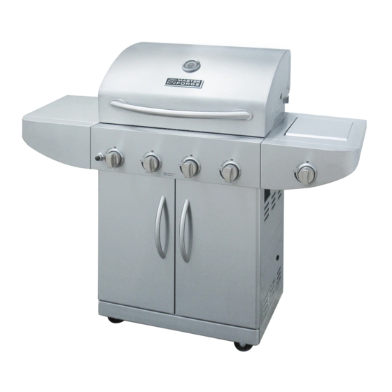
4-BURNER GAS GRILL
1
ITEM #0097709
MODEL #
1010037
Advertisement
Table of Contents

Related Manuals for Master Forge 1010037


Summary of Contents for Master Forge 1010037
- Page 1 ITEM #0097709 4-BURNER GAS GRILL MODEL # Master Forge & M Design® is a 1010037 registered trademark of LF, LLC. All rights reserved. WARNING Improper installation, adjustment, alteration, service or maintenance can cause injury or property damage. Read this instruction manual thoroughly before installing or servicing this equipment.
-
Page 2: Table Of Contents
TABLE OF CONTENTS Safety Information………………………………………………………………………………….3 Package Contents……………………………..…………………….…….……………………..5 Hardware Contents………………………………….……………………….…………..…….…..7 Preparation………………….…….………………………….………………….………...….….….7 Assembly Instructions……………………..………………………….……………….……..……8 Installation Instructions…………………………………………………………………………...17 Operating Instructions…………………………………………………………………………… 21 Care and Maintenance…………………………………………………………………………….24 Troubleshooting . ………………………………………………………………………………….30 Warranty………………………………………………………………………………………….…..32 Replacing Main Burner…………………………………………………………………………….33 Exploded View ……………………………………………………………………………….……34 Replacement Parts List………………………………………………………………………… 35 Converting to Natural Gas Kit #0050772……………………… ………………………….…... 37... - Page 3 SAFETY INFORMATION Please read and understand this entire manual before attempting to assemble, operate or install the product. If you have any questions regarding the product, please call customer service at 1-800-963-0211 Monday through Thursday from 8:00 a.m. to 6:00 p.m. EST, Friday from 8:00 a.m.
-
Page 4: Safety Information
SAFETY INFORMATION 17. Do not store a spare LP-gas cylinder under or near this appliance. 18. Never fill the cylinder beyond 80 percent full. 19. If the information in “17” and “18” is not followed exactly, a fire causing death or serious injury may occur. -
Page 5: Components View
PACKAGE CONTENTS... - Page 6 PACKAGE CONTENTS Part Description Quantity Part Description Quantity Warming rack Left cart door Cooking grate Door handle Flame tamer Door handle grommet Right shelf Cart heat shield Right shelf front Cart support bracket Right shelf bracket Locking caster Bezel Cart base Control knob Cart support beam Cart back panel...
-
Page 7: Hardware Contents
HARDWARE CONTENTS 1/4-20 Lock 1/4-20 x 5/16 in. 5/32-32 x 3/8 in. 1/4-20 x 1/2 in. 1/4-20 x 3/8 in. Screw Screw Washer Screw Screw Qty. 23 Qty. 26 Qty. 22 Qty.10 Qty.16 Allen Wrench AA Battery PREPARATION Before beginning assembly of product, make sure all parts are present. Compare parts with package contents list and hardware contents list. - Page 8 ASSEMBLY INSTRUCTIONS 1. Fix the tank tray bolt Remove the LP tank bolt on the cart base (W) as shown in Fig. 1A and then reinstall as shown in Fig. 1B. Tank tray bolt Note: For all of the following steps, do not tighten any screws completely until all screws for that step have been installed.
- Page 9 ASSEMBLY INSTRUCTIONS 3. Attach door catch plate Turn the cart base (W) assembly right side up as shown in Fig. 3. Attach door catch plate (Y) to cart base (W) using 2 5/32-32 x 3/8 in. screws (AA). Hardware Used 5/32-32 x 3/8 in.
- Page 10 ASSEMBLY INSTRUCTIONS 6. Install LP tank barrier bar Attach the LP tank barrier bar (O) as the arrows indicate to the cart back panel (I) and the cart base (W) using 2 5/32-32 x 3/8 in. screws (AA) as shown in Fig. 6. The right install direction should be same as the indicate.
- Page 11 ASSEMBLY INSTRUCTIONS 9. Install cart heat shield Attach the cart heat shield (T) to the cart back panel (I) using 2 5/32-32 x 3/8 in. screws (AA). Note that the heat shield installs under the lip of the cart back panel (I) as shown in Fig Next attach the cart heat shield (T) to the cart support...
- Page 12 ASSEMBLY INSTRUCTIONS 11. Install grease tray Remove the pre-installed screw from the right of the greasy tray (D1). From the back of the grill, slide the grease tray (D1) onto the ledges on the left and right sides of the grill head as shown in Fig.
- Page 13 ASSEMBLY INSTRUCTIONS 14. Install door handles Attach door handle (R) to the left cart door (Q) using 2 door handle grommets (S) and 2 1/4-20 x 1/4 in. screws (EE) as shown in Fig. 14. Repeat installation for right cart door (A1). Hardware Used 1/4-20 x 5/16 in.
- Page 14 ASSEMBLY INSTRUCTIONS 17. Install side shelves Starting with the right side, loosen the 2 pre-installed screws marked “a” and “c” and then completely remove screw “b” as shown in Fig. 17A. Using the shelf keyhole slots, slide the right shelf onto the 2 loosened screws as shown in Fig.
- Page 15 ASSEMBLY INSTRUCTIONS 18. Install side burner valve a) Loosen but do not remove the two pre-installed screws from the side burner valve as shown in Fig. 18A. b) Insert the side burner valve screws through the keyhole slots in the front of the side burner shelf and then slide the valve upward so the screws rest in the small section of the keyhole slots.
-
Page 16: Assembly Instructions
ASSEMBLY INSTRUCTIONS 19. Install cooking components Install 4 flame tamers (C) into grill head (K) directly over the main burners. The flame tamers rest in notches built into the inside of the grill head (K). Place cooking grates (B) into the grill head (K) on the ledges above the flame tamers. - Page 17 INSTALLATION INSTRUCTIONS For Portable LP-Gas Connection From front of the cart, place foot ring of 20 lb. tank into the hole in bottom panel. Make sure the tank valve is in OFF position. Use the tank bolt to secure the tank in a fixed position. Before installing your gas tank, lift up the safety tank ring (as shown in Fig.
-
Page 18: Installation Instructions
INSTALLATION INSTRUCTIONS 2. When connecting the regulator/burner valve assembly to the tank valve, turn the large plastic nut clockwise until it stops. 3. Gas will not flow unless the plastic nut is completely connected. 4. HAND TIGHTEN ONLY. b. Hand Disassembly: 1. - Page 19 INSTALLATION INSTRUCTIONS LP Gas If your grill is for LP gas, the regulator supplied is set for 11 in. water column (WC) and is for use with LP gas only. The factory-supplied regulator and hose must be used with a 20 lb. LP gas tank.
- Page 20 INSTALLATION INSTRUCTIONS However, the manufacturer strongly suggests a 6 ft. clearance of the grill to combustible constructions. Clearance to Noncombustible Construction A minimum clearance of 48 in. from the back of the grill above the cooking surface to noncombustible constructions is required to allow the grill hood to open completely. A minimum of 48 in.
-
Page 21: Operating Instructions
OPERATING INSTRUCTIONS Grill Lighting Instructions To Light the Main Burners and the Side Burner 1. Make sure the control knobs are in the “OFF” position. 2. Open the grill hood. 3. Check the ignition pin position and distance between the pin and the burner. - Page 22 OPERATING INSTRUCTIONS Match Lighting Instructions IMPORTANT: The hood must be open when match lighting any burner. 1. Turn on gas supply. a. If portable, at the LP cylinder valve. b. If permanent gas supply, at the manual gas shutoff valve. 2.
- Page 23 OPERATING INSTRUCTIONS Preheating Grill It is extremely important that your grill be up to temperature before you begin using it. After lighting, close the hood and preheat the grill on “HIGH” for 15 minutes. This preheating will ensure that the cooking grid and grate are hot enough for proper grilling. CAUTION: Do not cover the grids during the preheating period.
- Page 24 CARE AND MAINTENANCE Burner Flame Check Visually check the burner flames prior to each use. The flames should appear blue. If they do not, refer to the section on cleaning burner tubes and ports. Before cooking on your grill the first time, wash cooking grids and cooking rack with warm, soapy 1 in.
-
Page 25: Care And Maintenance
CARE AND MAINTENANCE WARNING Do not attempt to turn off the LP tank valve without first covering your hand with a protective mitt or allowing the grill to cool down. Failure to follow this warning could result in a severe burn. LP Gas Safety Requirements For LP gas grills, the LP gas supply tank to be used must be: Constructed and marked in accordance with the Specifications for LP Gas Tanks of the U.S. - Page 26 CARE AND MAINTENANCE Handling the Liquid Propane Tank Safely Remember to handle your portable liquid propane tank carefully when you take it to your dealer for a refill. Avoid dropping it or bumping it against sharp objects. Liquid propane tanks are sturdily constructed, but a series of hard jolts could damage the container.
- Page 27 CARE AND MAINTENANCE WARNING: When not connected to your grill, the LP gas tank must be stored in an upright position in a cool, shady, well-ventilated, outdoor location away from your grill or any other heat source. Failure to follow this warning could lead to tank valve damage, fire hazard and personal injury.
- Page 28 CARE AND MAINTENANCE Specks of grease can gather on the surface of the stainless steel and get baked-on. These can usually be removed with warm soapy water or a stainless steel cleaner. As a last resort a mild abrasive pad could be used with a stainless cleaner. Use light pressure on the pad and always scrub in the direction of the grain.
- Page 29 CARE AND MAINTENANCE Care and Maintenance Time Table Chart Grill Item Frequency Based on Normal Use Cleaning Method Painted surface Twice yearly Car wax Stainless surface Twice yearly Stainless cleaner All grates After each use Burn off and wipe Stainless grates 15 days Wire brush/Dishwasher safe Porcelain grates...
-
Page 30: Troubleshooting
TROUBLESHOOTING PROBLEM POSSIBLE CAUSE CORRECTIVE ACTION Grill or side cooker 1. The ignition wire came off 1. Reconnect the ignition wire to the the electrical igniter/valve. electrical igniter/valve. will not light. 2. The distance between the 2. Loosen the ignition pin and adjust the ignition pin and the burner distance, then fasten it again. - Page 31 TROUBLESHOOTING PROBLEM POSSIBLE CAUSE CORRECTIVE ACTION Low heat with the 1. Low heat is found in natural 1. This model is set for 7 in. natural knob in “HIGH” gas models. gas usage. Please check your position. natural gas supply system to have 2.
-
Page 32: Warranty
WARRANTY Proof of purchase is required to access this warranty program, which is in effect from the date of purchase. Customers will be subject to parts, shipping, and handling fees if unable to provide proof of the purchase or after the warranty has expired. If you have any questions or problems, you can call our customer service department at 1-800-963-0211, 8 a.m. -
Page 33: Replacing Main Burner
REPLACING MAIN BURNER How to replace the main burner 1. Open the grill hood and remove the warming rack (A), cooking grates (B) and flame tamers (C) as shown in Fig. 1. 2. Remove the cotter pin from the main burner, as shown in Fig. - Page 34 5. Feed the new main burner electrode wire through the hole on the inside of the Push button igniter lock grill and then reinstall the main burner nut and push button electrode with the two screws previously removed. Fig. 04. 6.
-
Page 35: Exploded View
EXPLODED VIEW For replacement parts, call our customer service department at 1-800-963-0211, 8 a.m. – 6 p.m., EST, Monday - Thursday, 8 a.m. - 5 p.m., EST, Friday. -
Page 36: Replacement Parts List
REPLACEMENT PARTS LIST PART DESCRIPTION QTY. PART DESCRIPTION QTY. Grill Hood Grease Tray Hood Hinge Screw Grease Cup Temperature Gauge Bezel Back Grill Head Cover Temperature Gauge Heat Cart Heat Shield Insulating Spacer Temperature Gauge Cart Back Panel Hood Bumper Left Shelf Bracket Hood Handle Bezel Heat Left Shelf... - Page 37 REPLACEMENT PARTS LIST PART DESCRIPTION QTY. PART DESCRIPTION QTY. Main Burner Electrode & Side Burner Wire A Right Shelf Bracket Cotter Pin Right Shelf Front Flame Tamer Right Shelf Cooking Grate Side Burner Pan Warming Rack Side Burner Igniter Instruction Manual Side Burner Grate Hardware Pack Side Burner Lid...
-
Page 38: Converting To Natural Gas Kit #0050772
CONVERTING TO NATURAL GAS KIT #0050772 Should you decide to convert your gas grill Item #0097709 Model 1010037 from propane to natural gas, use conversion kit item #0050772. Your #0050772 kit will contain 4 -1.44 main burner orifices. Install all of them following your kit instructions. - Page 39 CONVERTING TO NATURAL GAS KIT #0050772 Take the knobs off valve stems and adjust the screws as shown using the slotted screwdriver. Turn the screw clockwise until it stops. Make sure to completely tighten the screws. Failure to tighten the screws will result in the low heat setting working improperly.
Need help?
Do you have a question about the 1010037 and is the answer not in the manual?
Questions and answers
how do I get to the igniter for replacement (Model 1010037)
To access the igniter for replacement on the Master Forge model 1010037:
1. Remove the main burner nut and push button electrode by taking out the two screws.
2. Plug the wire into the back of the new push button igniter where the previous wire was removed.
3. Reinstall the push button igniter lock nut and push button.
4. Reinstall the ignition heat shield using the two screws removed earlier.
5. Replace the flame tamers, cooking grates, and warming rack.
This answer is automatically generated