Advertisement
Table of Contents
- 1 Grill Operation
- 2 Table of Contents
- 3 Safety Information
- 4 Package Contents
- 5 Hardware Contents
- 6 Preparation
- 7 Assembly Instructions
- 8 Natural Gas Conversion
- 9 Operating Instructions
- 10 Care and Maintenance
- 11 Troubleshooting
- 12 Warranty
- 13 Exploded View
- 14 Replacement Parts List
- Download this manual
Master Forge & M Design® is a
registered trademark of LF, LLC.
All rights reserved.
WARNING
Improper installation, adjustment,
alteration, service or maintenance
can cause injury or property
damage. Read this instruction
manual thoroughly before installing
or servicing this equipment.
WARNING
1. Do not store or use gasoline or
other flammable vapors and
liquids in the vicinity of this or any
other appliance.
2. An LP tank not connected for use
should not be stored in the vicinity
of this or any other appliance.
DANGER
If you smell gas:
1. Shut off gas to the appliance.
2. Extinguish any open flames.
3. Open the lid.
4. If the odor continues, keep away
from the appliance and
immediately call your gas supplier
or fire department.
WARNING
For Outdoor Use Only
Serial Number
Questions, problems, missing parts? Before returning to your retailer, call our
customer service department at 1-800-963-0211, 8 a.m. - 6 p.m., EST, Monday -
Thursday, 8 a.m. - 5 p.m., EST, Friday.
AB13611
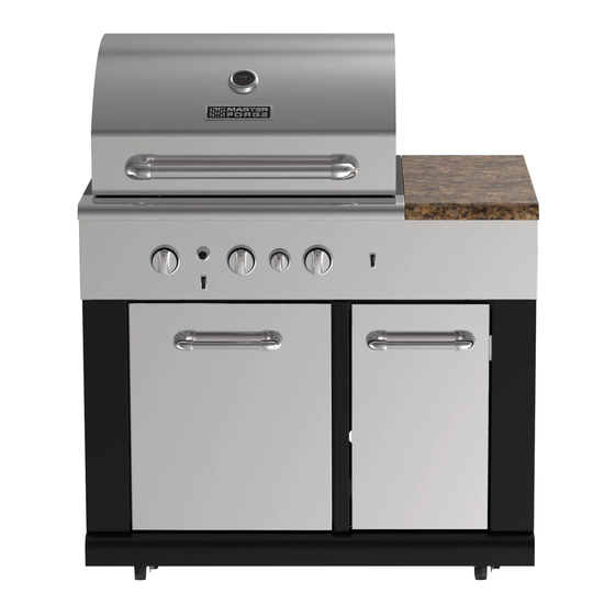
3-BURNER MODULAR GRILL
ATTACH YOUR RECEIPT HERE
Purchase Date
1
ITEM #0503225
MODEL #BG1793B-A
Español p. 40
Advertisement
Table of Contents

Related Manuals for Master Forge BG1793B-A


Summary of Contents for Master Forge BG1793B-A
- Page 1 ITEM #0503225 3-BURNER MODULAR GRILL MODEL #BG1793B-A Master Forge & M Design® is a registered trademark of LF, LLC. All rights reserved. Español p. 40 WARNING Improper installation, adjustment, alteration, service or maintenance can cause injury or property damage. Read this instruction manual thoroughly before installing or servicing this equipment.
-
Page 2: Grill Operation
Grill Operation 1-2-3 Before Grilling: Step 1 Keep your grill a safe distance away from your property.* Step 2 Always perform a leak test.* Step 3 Keep children away from the grill. During Grilling: (To avoid tripping safety valves, please follow these instructions carefully!) Step 1 First open lid and turn gas tank on slowly. -
Page 3: Table Of Contents
TABLE OF CONTENTS Safety Information…………………………………….………...….………….………….…. ………4 Package Contents…..………………..…..….……...…....………………………………..6 Hardware Contents……………………………………………………………….……………………7 Preparation…..………………..…………………..….……………………………………………..….7 Assembly Instructions……………………..……………….………………………………………...8 Natural Gas Conversion……………………………………………..........12 Operating Instructions…………………………….……...…………………………....19 Care and Maintenance……………………………….………………………………………………28 Troubleshooting …………………………………………………………………..….……………...33 Warranty………………………………………………………………………………………………..36 Exploded View……………….………………………………………………………………………..37 Replacement Parts List…….………………………………………………………………………..38... -
Page 4: Safety Information
SAFETY INFORMATION Please read and understand this entire manual before attempting to assemble, operate or install the product. If you have any questions regarding the product, please call customer service at 1-800-963-0211 Monday through Thursday from 8:00 a.m. to 6:00 p.m. EST, Friday from 8:00 a.m. - Page 5 SAFETY INFORMATION 16. The cylinder used must include a collar to protect the cylinder valve. 17. Do not store a spare LP-gas cylinder under or near this appliance. 18. Never fill the cylinder beyond 80 percent full. 19. If the information in “17” and “18” is not followed exactly, a fire causing death or serious injury may occur.
-
Page 6: Package Contents
PACKAGE CONTENTS PART DESCRIPTION QUANTITY PART DESCRIPTION QUANTITY Main Body Flame Tamer Warming Rack Trash Bin Grid Small Knob Drip Tray... -
Page 7: Hardware Contents
HARDWARE CONTENTS AA Battery 9V Battery Orifice Phillips Conversion Qty. 1 Qty. 1 Removal Tool Screwdriver Screw Qty. 1 Qty. 1 Qty. 3 Φ1.45mm 17 x 19 mm Φ1.30mm Grill Cover Orifice Wrench Orifice Qty. 1 Qty. 3 Qty. 1 Qty. -
Page 8: Assembly Instructions
ASSEMBLY INSTRUCTIONS Remove all the packing material from inside and outside the grill. 2. Place all three flame tamers (E) on top of each burner on the main body (A). 3. Place the grids (C) on the main body (A) as shown. - Page 9 ASSEMBLY INSTRUCTIONS Place the warming rack (B) as shown. 5.Open the cabinet door of the main body (A) and place the drip tray (D) in position as shown. 6.Unscrew the igniter push button cap on the main body (A) and feed the “AA” battery (AA) into the igniter module with the positive (+) end facing out.
- Page 10 ASSEMBLY INSTRUCTIONS 7. Open the cabinet door of the main body (A) and place the 9V battery (BB) for the control panel light as shown. Hardware Used 9V Battery 8. Screw the small knob (G) into place on the knob bezel on the main body (A). 9.
- Page 11 ASSEMBLY INSTRUCTIONS 10. Your grill is now assembled.
-
Page 12: Natural Gas Conversion
NATURAL GAS CONVERSION PREPARATION: IMPORTANT: The 10 ft. Natural Gas Hose is NOT INCLUDED. 10 ft. Natural Gas Hose Before beginning conversion, make sure all parts are present. Compare parts with package contents. If any part is missing or damaged, do not attempt to convert. Contact customer service for replacement parts. - Page 13 NATURAL GAS CONVERSION IMPORTANT: After your grill is converted to natural gas, the working pressure for natural gas is 7 in. water column (WC). Gas pressure is affected by gas line size and the length of gas line run from house.
- Page 14 NATURAL GAS CONVERSION CONVERSION INSTRUCTIONS: Before the conversion, make sure all control knobs are in the OFF position, LP tank valve is closed, and tank is disconnected from regulator and removed from grill. 1. Before the conversion, make sure all control knobs are in the OFF position, LP tank valve is closed, and tank is disconnected from regulator and...
- Page 15 NATURAL GAS CONVERSION 3. Adjust the air shutters of the main burners by loosening the air shutter screws with the Phillips screwdriver (DD). Hardware Used Phillips Screwdriver 4. Remove the LP orifices of all the main burners with the orifice removal tool (CC) and install theΦ1.45mm orifices (FF).
- Page 16 NATURAL GAS CONVERSION 6. Use the 17 x 19 mm wrench (GG) to remove the hex nut securing the rotisserie burner orifice and hose assembly. Detach the assembly from the bracket. Remove the LP orifice of the rotisserie burner with the orifice removal tool (CC) and install the Φ1.30mm orifice (HH).
- Page 17 NATURAL GAS CONVERSION 9. Pull off the control knob of the 3 main burners. Use the Phillips screwdriver (DD) to attach the conversion screw (EE) to the back of the knobs. Re-install all the knobs. The conversion screw must be attached properly.
- Page 18 NATURAL GAS CONVERSION 11. When converting to natural gas, please be aware that the low heat setting LP LOW of the main burners is “NG LOW” as shown on the control panel. “LP LOW” setting is not applied when converting to natural gas.
-
Page 19: Operating Instructions
OPERATING INSTRUCTIONS Never attach an unregulated gas line to the appliance. Connection to an unregulated gas line can cause excessive heat or fire. Verify the type of gas supply to be used, either Natural Gas (N.G.) or Liquid Propane (L.P.), and make sure the serial plate agrees with that of the supply. - Page 20 OPERATING INSTRUCTIONS L.P. GAS INSTALLATION Gas grills that are set to operate with L.P. gas come with a high capacity hose and regulator assembly. (Note: Only use the pressure regulator and hose assembly supplied with the grill or a replacement pressure regulator and hose assembly specified by the manufacturer). This assembly is designed to connect directly to a standard 20 lb.
- Page 21 OPERATING INSTRUCTIONS 6. Connect the hose and regulator Fig. 5 assembly to the tank valve (See Fig. 5). Hand tighten the quick coupling nut clockwise to a full stop. DO NOT use a wrench to tighten because it could damage the quick coupling nut and result in a hazardous condition.
- Page 22 OPERATING INSTRUCTIONS Disconnecting A Liquid Propane Gas (LP Gas) Tank From Your Grill: Fig. 8 1. Turn the burner knobs and LP gas tank valve to the full OFF position. (Turn clockwise to close.) 2. Detach the hose and regulator assembly from the LP gas tank valve by turning the quick coupling nut counterclockwise.
- Page 23 OPERATING INSTRUCTIONS • The regulator and hose assembly must be inspected before each use of the grill. If there is excessive abrasion or wear or if the hose is cut, it must be replaced prior to the grill being used again.
- Page 24 OPERATING INSTRUCTIONS WARNING When leak testing this appliance, make sure to test and tighten all loose connections. A slight leak in the system can result in a low flame or hazardous condition. Most L.P. gas tanks now come equipped with a leak detector mechanism internal to the tank. When gas is allowed to escape rapidly, it shuts off the gas supply.
- Page 25 OPERATING INSTRUCTIONS BEFORE AND AFTER LIGHTING 1. Ensure your grill is located on a level surface. 2. Keep the gas grill area clean and free from combustible materials, gasoline, and other flammable vapors and liquids. 3. Ensure nothing is obstructing the flow of combustion and ventilation air. 4.
- Page 26 OPERATING INSTRUCTIONS GRILL BURNER LIGHTING Warning: Do not lean over grill when lighting. Turn off LP supply at cylinder when appliance is not in use. Main Burner Lighting Illustration: 1. Check that the control knobs are in the OFF position. 2.
- Page 27 OPERATING INSTRUCTIONS If ignition does not take place within 5 seconds, immediately turn the control knob to the OFF position. Wait 5 minutes and repeat step 4 above or refer to match lighting instructions in manual. If the igniter does not function, the burner can be lit by holding a lit match to the burner while the control knob is turned counter-clockwise to “HIGH.”...
-
Page 28: Care And Maintenance
CARE AND MAINTENANCE INFRARED BURNER CLEANING After each use, it is necessary to burn the bottom infrared burner with the hood open for at least five minutes to vaporize any food drippings or particles. Failure to perform this step will damage the burner. It may occasionally be necessary to brush, blow, or vacuum accumulated ash from the burner surface. - Page 29 CARE AND MAINTENANCE GRANITE MAINTENANCE Outdoors can be very harsh on the granite of your grill. Dirt, pollen and even UV rays can affect the granite. Please follow these instructions to preserve the granite’s natural beauty: - Granite is a hard, non-porous natural stone and is relatively not affected by harsh chemicals. However, it is recommended to use a neutral cleaner or stone soap (available in hardware stores or from a stone dealer), or a mild dishwashing liquid and warm water.
- Page 30 CARE AND MAINTENANCE STAINLESS STEEL After initial usage, areas of the grill may discolor from the intense heat given off by the burners. This is normal. Purchase a mild stainless steel cleaner and rub in the direction of the grain of the metal. Specks of grease can gather on the surface of the stainless steel and bake on to the surface and give a worn appearance.
- Page 31 CARE AND MAINTENANCE Definitions: (+) Guard – Guard is a portion of portable luminaries unit that prevents inadvertent contact with the bulb. It may be integrated with the UV filter or lamp containment barrier or as part of an enclosure or shade. (+) Lamp containment barrier –...
- Page 32 CARE AND MAINTENANCE WARNING The light glass cover should not be in contact with water or any other liquid when it’s warm. Sudden change of temperature may cause cracks on glass cover. WARNING To ensure continued protection against electric shock: 1.
-
Page 33: Troubleshooting
TROUBLESHOOTING Many solutions given here can make your grilling experience safer and more enjoyable. You can also call customer service department at 1-800-963-0211, 8 a.m. - 6 p.m., EST, Monday - Thursday, 8 a.m. - 5 p.m., EST, Friday. PROBLEM POSSIBLE CAUSE CORRECTIVE ACTION 1. - Page 34 TROUBLESHOOTING PROBLEM POSSIBLE CAUSE CORRECTIVE ACTION 1. This model is set for 7 in. natural gas usage. Please check your natural gas supply system to have correct gas pressure. Regulator is not needed for NG model. Low heat 1. Low heat is found in natural Check the orifice if you installed NG with the knob gas models.
- Page 35 TROUBLESHOOTING PROBLEM POSSIBLE CAUSE CORRECTIVE ACTION 1. Install 9V battery in the LED battery box. 1. No power supply. 2. Check all wiring connections between 2. Damaged wiring or loose LED control the battery box and the LED. Also connection. panel lights check the connections between the 3.
-
Page 36: Warranty
WARRANTY Proof of purchase is required to access this warranty program, which is in effect from the date of purchase. Customers will be subject to parts, shipping, and handling fees if unable to provide proof of the purchase or after the warranty has expired. If you have any questions or problems, you can call our customer service department at 1-800-963-0211, 8:00 a.m. -
Page 37: Exploded View
EXPLODED VIEW For replacement parts, call our customer service department at 1-800-963-0211, 8 a.m. – 6 p.m., EST, Monday - Thursday, 8 a.m. - 5 p.m., EST, Friday. -
Page 38: Replacement Parts List
REPLACEMENT PARTS LIST PART DESCRIPTION QUANTITY PART DESCRIPTION QUANTITY Hood Assembly Hood Handle Hood Handle Bracket Hood Handle Washer Hood Silica Pad Thermometer Hood Axis Warming Rack Cooking Grate Flame Tamer Rear Infrared Burner Rear Cover Assembly Hood Left Lighting Hood Right Lighting Assembly Assembly... - Page 39 Right Side Cart Panel Cart Real Panel Assembly Base Panel Trash Bin Door Assembly Support Panel Unlocked Castor Locked Castor Hardware Pack Grill Cover Master Forge & M Design® is a registered trademark of LF, LLC. All rights reserved. Printed in China...
Need help?
Do you have a question about the BG1793B-A and is the answer not in the manual?
Questions and answers