Advertisement
MASTER FORGE and logo design are trademarks or registered trademarks of LF, LLC. All rights reserved.
WARNING
FOR YOUR SAFETY:
DO NOT LEAVE THIS APPLIANCE UNATTENDED
WHILE IN USE, ESPECIALLY COOKING THE FAT-
TY MEAT AND CLOSE THE LID TOO LONG TIME.
WARNING
FOR YOUR SAFETY:
For Outdoor Use Only
(outside any enclosure)
WARNING
FOR YOUR SAFETY:
Improper installation, adjustment, alteration,
service or maintenance can cause injury or
property damage. Read this instruction manual
thoroughly before installing or servicing this
equipment.
WARNING:
expose you to chemicals including carbon
monoxide, soot, lead and lead components,
which are known to the State of California
to cause cancer and birth defects or other
reproductive harm.For more information go to
www.P65Warnings.ca.gov.
DANGER
Never operate this appliance unattended.
ATTACH YOUR RECEIPT HERE
Serial Number
Questions, problems, missing parts? Before returning to your retailer, call
our customer service department at 1.800.963.0211, 8 a.m. - 8 p.m., EST,
Monday - Sunday. You could also contact us at partsplus@lowes.com or
visit www.lowespartsplus.com.
VR21106
This product can
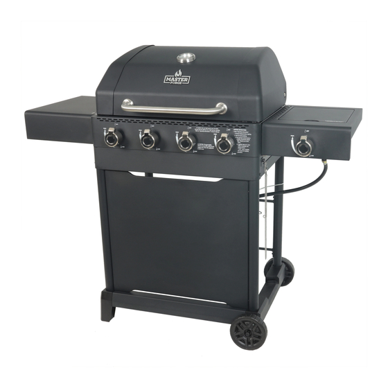
4-BURNER GAS GRILL WITH SIDE BURNER
If you smell gas -
1. Shut off gas to appliance.
2. Extinguish any open flame.
3. Open lid.
4. If odor continues, keep away from the
appliance and immediately call your gas
supplier or your fire department.
1. Do NOT store or use gasoline or other
flammable liquids or vapors in the vicinity of
this or any other appliance.
2. An LP cylinder not connected for use shall
NOT be stored in the vicinity of this or any
other appliance.
Purchase Date
ITEM#4082878
MODEL#GBC22491L
DANGER
WARNING
FOR YOUR SAFETY:
GBC22491L-RA-OM-F104
Español p.27
Advertisement
Table of Contents

Related Manuals for Master Forge GBC22491L


Summary of Contents for Master Forge GBC22491L
- Page 1 ITEM#4082878 4-BURNER GAS GRILL WITH SIDE BURNER MODEL#GBC22491L Español p.27 MASTER FORGE and logo design are trademarks or registered trademarks of LF, LLC. All rights reserved. WARNING FOR YOUR SAFETY: DO NOT LEAVE THIS APPLIANCE UNATTENDED WHILE IN USE, ESPECIALLY COOKING THE FAT- TY MEAT AND CLOSE THE LID TOO LONG TIME.
-
Page 2: Table Of Contents
TABLE OF CONTENTS Safety Information ....... Page 2 Package Contents ........5 Hardware Contents . - Page 3 SAFETY INFORMATION W Check for leaks even if your unit was assembled Dangerous Goods; and Commission. for you by someone else. W LP gas cylinder must be arranged for vapor W Do NOT operate if a gas leak is present. Gas withdrawal.
- Page 4 SAFETY INFORMATION W Do NOT attempt to disconnect the gas regulator cause a fire or an explosion that can damage from the cylinder or any gas fitting while the grill property and cause serious bodily injury or is in use. death.
-
Page 5: Package Contents
PACKAGE CONTENTS... -
Page 6: Hardware Contents
PACKAGE CONTENTS Part Description Quantity Part Description Quantity Warming Rack Grease Cup Side Cart Frame Cooking Grid Heat Plate Rear Leg Lid Handle* Front Leg Cart Frame Support A Temperature Gauge Upper Cart Frame Lid* Rear Cart Frame Support Grill Body Assembly* LP Gas Tank Retainer Wire Main Burner* Left Leg Seat... -
Page 7: Assembly Instructions
ASSEMBLY INSTRUCTIONS Step 1: Install Front Leg and Lower Cart Frame on Right Leg Seat. Insert the front leg (T) into right leg seat (AB). First Align the holes in the front leg (T) and lower cart frame (AE). Then insert the M6x16 screw (BB) into the holes shown in Fig.1. - Page 8 ASSEMBLY INSTRUCTIONS Step 3: Install Rear Leg and Cart Frame Support A Insert one rear leg (S) into left leg seat (Y). Align the holes in one rear leg (S), left leg seat (Y) First and cart frame support A (U). Then insert the M6x16 screw (BB) into the holes shown in Fig.3.
- Page 9 ASSEMBLY INSTRUCTIONS Step 5: Install Side Cart Frame Align the holes in the side cart frames (R) and rear legs (S). Then insert the M6x16 screw (BB) into the holes shown in Fig.5. Tighten both screws complelely. NOTE: Only screw the back end of side cart frames for this step.
- Page 10 ASSEMBLY INSTRUCTIONS Step 7: Attach Rear Cart Frame Support Attach the rear cart frame Support (W) with three M6x16 screws (BB). NOTE: Don't screw the left upper hole of the rear cart frame Support until step 9 is completed. Hardware Used M6x16 Screw Step 8: Attach Wheels and Axle...
- Page 11 ASSEMBLY INSTRUCTIONS Step 9: Attach Cart Frame Support B Attach the cart frame support B (Z) with one M6x16 screw (BB). NOTE: Align the holes in the cart frame support B Second and rear cart frame support. Then insert the M6x16 screw (BB) into the holes shown in Fig.9.
- Page 12 ASSEMBLY INSTRUCTIONS Step 11: Attach Upper Cart Frame Attach the upper cart frame (V) with two M6x16 screws (BB). NOTE: Slide the upper cart frame in first and align the holes in the side cart frame (R) and upper cart frame (V).
- Page 13 ASSEMBLY INSTRUCTIONS Step 13: Attach Grill Body Assembly Attach the grill body assembly (G) with four M6x16 bolt (CC), Ø16 washer (FF) and Ø6 lock washer (GG). NOTE: Two people are needed to perform this step. Hardware Used M6x16 Bolt Ø16 Washer Ø6...
- Page 14 ASSEMBLY INSTRUCTIONS Step 15: Attach Left Side Shelf Attach the left side shelf(J) with four M6x16 bolt First (CC). NOTE: Insert two bolts into the upper holes with leaving 5 mm threads exposed. Then slide the left side shelf onto the bolts and insert the other two bolts into the lower holes shown in Fig.15.
- Page 15 ASSEMBLY INSTRUCTIONS Step 17: Install Side Burner Valve on Right Side Shelf. Install the side burner valve (M) with two M4x10 screws (AA). Hardware Used M4x10 Screw Step 18: Attach Side Burner First Attach the side burner (P) to the right side shelf (N) by using two M4x10 screw (AA).
- Page 16 ASSEMBLY INSTRUCTIONS Step 19: Connect Side Burner Ignition Wire Connect the side burner ignition wire as illustrated. NOTE: Failure to plug the wire to the ignitor electrode will result in no ignition. Step 20: Attach Side Burner Grid Put the side burner grid (O) onto the right side shelf (N) by aligning the legs with the slots.
- Page 17 ASSEMBLY INSTRUCTIONS Step 21: Attach Heat Plates Put the heat plates (C) into place. Step 22: Attach Cooking Grid Put the cooking grids (B) into place. Step 23: Attach Warming Rack Put the warming rack (A) into place.
- Page 18 ASSEMBLY INSTRUCTIONS Step 24: Attach Control Knobs Push five control knobs (K) onto the stem of the valve. Step 25: Attach Grease Cup Insert the grease cup (Q) into the grill body.
-
Page 19: Installation Instructions
INSTALLATION INSTRUCTIONS To operate, you will need one precision-filled standard grill LP gas tank with external valve threads. CAUTION 20 lb W LP gas tank must be properly disconnected 9 Kg and removed prior to moving this grill. Inserting LP Gas Tank 12.2 in. -
Page 20: Operating Instructions
OPERATING INSTRUCTIONS Figure 1 Main Burners Checking for Leaks LP Gas Connection Burner Connections 1. Make sure the regulator hose and valve connections are securely fastened to the burner and the tank. 2. Visually check the connection between the burner / venturi tube and orifice. 3. - Page 21 OPERATING INSTRUCTIONS(CONTINUED) W CAUTION: If burner flame goes out during operation, immediately turn Figure 5 the control knobs to the “ OFF” position, LP gas tank valve “CLOSED” and open lid to let the gas clear for 5 minutes before re-lighting. Match Turning Off 1.
-
Page 22: Care And Maintenance
OPERATING INSTRUCTIONS(CONTINUED) 1. If igniter does not light burner, use a lit match secured with the lighting rod (included with grill) to light burners. Position the lit match near side of the burner (Figure 7). 2. Important: Always use the lighting rod (included) when lighting burner with a match. After lighting, observe the burner flame. - Page 23 CARE AND MAINTENANCE(CONTINUED) 1. Remove burners by removing the fasteners, which secure the burners to the Figure 8 grill bottom. 2. Lift burners up and away from gas valve orifice. Burner Flame Conditions 3. Disconnect wire from spark electrode. Use this chart to see if your burners need 4.
-
Page 24: Limited Warranty
LIMITED WARRANTY Proof of purchase is required to access this warranty program, which is in effect from the date of purchase. Customers will be subject to parts, shipping, and handling fees if unable to provide proof of the purchase or after the warranty has expired. If you have any questions or problems, you can call our customer service department at 1-800-963- 0211, 8 a.m. - Page 25 TROUBLESHOOTING Check if LP gas tank is empty A. If empty, exchange, refill or replace LP gas tank No gas flow B. If LP gas tank is not empty, refer to “Sudden drop in gas flow or reduced flame height” (see below) LP gas tank is low or empty Exchange, refill or replace LP gas tank 1.
-
Page 26: Replacement Parts List
REPLACEMENT PARTS LIST For replacement parts, call the customer service department at 1.800.963.0211, 8 a.m. - 8 p.m., EST, Monday - Sunday. You could also contact us at partsplus@lowes.com or visit www.lowespartsplus.com Part Description Part# Part Description Part# Warming Rack G22491-010 Grease Cup B0219-HA0...
Need help?
Do you have a question about the GBC22491L and is the answer not in the manual?
Questions and answers