Jøtul GF 400 DV Sebago Installation And Operation Instructions Manual
Jotul installation and operation instructions gas heater gf 400 dv
Hide thumbs
Also See for GF 400 DV Sebago:
- Installation and operation instructions manual (32 pages) ,
- Installation and operation instructions manual (32 pages) ,
- Installation and operation instructions manual (40 pages)
Table of Contents
Advertisement
Jøtul GF 400 DV
Sebago
Gas Heater
Installation
and
Operation
Instructions
WARNING:
IF THE INFORMATION IN THESE INSTRUCTIONS
ARE NOT FOLLOWED EXACTLY, A FIRE OR EXPLO-
SION MAY RESULT CAUSING PROPERTY DAMAGE,
PERSONAL INJURY OR LOSS OF LIFE.
FOR YOUR SAFETY:
DO NOT STORE OR USE GASOLINE OR OTHER
FLAMMABLE VAPORS AND LIQUIDS IN THE VICIN-
ITY OF THIS OR ANY OTHER APPLIANCE.
INSTALLATION:
INSTALLATION AND SERVICE MUST BE PER-
FORMED BY A QUALIFIED INSTALLER, SERVICE
AGENCY OR LICENSED GAS SUPPLIER.
THIS PRODUCT MUST BE INSTALLED BY A
LICENSED PLUMBER OR GAS-FITTER WHEN
INSTALLED IN THE COMMONWEALTH OF
MASSACHUSETTS.
A CARBON MONOXIDE (CO) DETECTOR SHALL
BE INSTALLED IN THE SAME ROOM AS THE
APPLIANCE.
WHAT TO DO IF YOU SMELL GAS:
• DO NOT TRY TO LIGHT ANY APPLIANCE.
• DO NOT TOUCH ANY ELECTRICAL SWITCHES.
• DO NOT USE THE PHONE IN YOUR BUILDING.
IMMEDIATELY CALL YOUR GAS SUPPLIER FROM A
NEIGHBOR'S PHONE.
• FOLLOW YOUR GAS SUPPLIER'S INSTRUCTIONS.
• IF YOU CANNOT REACH YOUR GAS SUPPLIER,
CALL THE FIRE DEPARTMENT.
AVERTISSEMENT:
ASSUREZ-VOUS DE BIEN SUIVRE LES INSTRUC-
TIONS DANS CETTE NOTICE POUR REDUIRE AU
MINIMUM LE RISQUE D'INCENDIE OU POUR EVITER
TOUT DOMMAGE MATERIEL, TOUTE BLESSURE OU
MORTALIT'E.
NE PAS ENTREPOSER NI UTILISER D'ESSENCE NI
OU LIQUIDES INFLAMMABLES DANS LE VOISINAGE
DE CET APPAREIL OU DE TOUT AUTRE APPAREIL.
L'INSTALLATION LE SERVICE DOIVENT ETRE
EXECUTES PAR UN INSTALLATEUR QUALIFIE,
AGENCE DE SERVICE OU LE FOURNISSEUR DE
GAZ.
QUE FAIRE SI VOUS SENTEZ UNE ODEUR DE GAZ.
• NE PAS TENTER D'ALLUMER L'APPAREIL
• NE TOUCHEZ A AUCUM NTERRUPTEUR.
• NE PAS VOUS SERVIR DES TELEPHONES SE
TROUVANT DANS LE BATIMENT OU VOUS VOUS
TROUVEZ.
• APPELEZ IMMEDIATEMENT VOTRE FOURNISSEUR
DE GAZ CHEZ UN VOISIN. SUIVEZ LES INSTRUC-
TIONS DU FOURNISSEUR.
• SI VOUS NE POUVEZ REJOINDRE LE
FOURNISSEUR DE GAZ, APPELEZ LE SERVICE DES
INCENDIES.
1
Advertisement
Table of Contents

Related Manuals for Jøtul GF 400 DV Sebago


Summary of Contents for Jøtul GF 400 DV Sebago
-
Page 1: And Operation
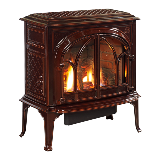
Jøtul GF 400 DV Sebago Gas Heater Installation Operation Instructions WARNING: IF THE INFORMATION IN THESE INSTRUCTIONS ARE NOT FOLLOWED EXACTLY, A FIRE OR EXPLO- SION MAY RESULT CAUSING PROPERTY DAMAGE, PERSONAL INJURY OR LOSS OF LIFE. FOR YOUR SAFETY:... - Page 2 With proper care and use, your Jøtul stove will provide you with many years of safe, dependable and satisfying service. The Jøtul GF 400 DV Sebago is a direct vented gas heater designed and approved for installation into a variety of configurations where close clearance to combustible material is required.
-
Page 3: Table Of Contents
Lighting Instructions ... Back Cover THIS PRODUCT MUST BE INSTALLED BY A LICENSED PLUMBER OR GAS-FITTER WHEN INSTALLED IN THE COMMONWEALTH OF MASSACHUSETTS. Jøtul GF 400 DV Sebago Direct Vent Gas Heater Manufactured and Distributed by: Jøtul A.S.A. Fredrikstad, Norway Jøtul North America... -
Page 4: Specifications
GF 400 DV Sebago Specifications Input Rates Natural Gas 32,000 BTU/hr. maximum input 18,000 BTU/hr. minimum input Propane 32,000 BTU/hr. maximum input 16,000 BTU/hr. minimum input Inlet Pressure: Natural Gas: 5.0 WC (1.24 kPa) Propane: 12.0 WC (2.99 kPa) 14.9 WC (3.71 kPa) -
Page 5: General Information
General Information THIS HEATER MUST BE INSTALLED AND MAINTAINED BY A QUALIFIED SERVICE AGENCY. The installation and repair of this appliance must be done by a qualified service person. Failure to properly install and maintain this heater could result in an unsafe or hazardous installation, which may result in a fire, explosion, property damage, personal injury or loss of life. -
Page 6: Safety Information
Young children should be supervised while they are in the same room as the GF 400 DV Sebago gas stove. Clothing or other flammable materials should not be placed ON or NEAR the GF 400 DV Sebago gas stove. -
Page 7: Clearances
Stove and Vent Clearance Requirements Minimum Clearances from the Stove to Combustibles: See figs. 2-4. Rear: 2” (51 mm) Ceiling: 32 1/4” (819 mm) Corner: 2” (51 mm) Sides: 3” (76 mm) Minimum Clearances from the Vent Pipe to Combustibles: Horizontal Run: Off the top of the pipe 2”... -
Page 8: Venting Requirements
Venting Requirements The Jøtul GF 400 DV Sebago gas stove may be installed with a vertical or horizontal termination and must conform to the configuration requirements described below. This appliance is approved for use with vent systems from the following manufacturers: •... -
Page 9: Vertical Termination
Figure 6. Adjusting the Air Inlet Restrictor plate - View is from the right side of the stove. Vertical Vent Termination The Jøtul GF 400 DV Sebago can be vertically vented through a ceiling or to a roof termination with the following guidelines:... - Page 10 Vent Termination Zones - Natural Gas Horizontal and Vertical Terminations for COAXIAL VENT • ALL VENTING MUST TERMINATE (END) WITHIN ONE OF THE SHADED AREAS. • SET STOVE EXHAUST RESTRICTOR TO THE POSITION THAT CORRESPONDS TO THE VENT TERMINATION AREA IN THE DIAGRAM ABOVE.
- Page 11 Vent Termination Zones - Propane Horizontal and Vertical Terminations for COAXIAL VENT • VENTING MUST TERMINATE (END) WITHIN ONE OF THE DESIG- NATED AREAS. ZONE “A” IS FOR VERTICAL TEMINATIONS ONLY. • SET STOVE EXHAUST RESTRICTOR TO THE POSITION THAT CORRE- SPONDS TO THE VENT TERMINATION AREA IN THE DIAGRAM ABOVE.
-
Page 12: Co-Linear Termination
Co-linear Vent Installation The GF 400 DV Sebago may be vented through a ma- sonry or Class A prefabricated chimney using a Co-linear Flexible Vent system approved for use with a solid-fuel burning fireplace. When installed in the manner de-... -
Page 13: Coaxial Chimney Conversion
Masonry or Prefabricated Chimney Conversion The GF 400 DV Sebago is approved for use with listed chimney conversion kits from any of the manufacturers listed on page 8. These kits are for use in a masonry chimney or a prefabricated solid fuel listed chimney. See fig. -
Page 14: Horizontal Termination
Horizontal Termination Any horizontal termination must fall within the shaded portion of the vent window graph illustrated in figs. 9 or 11. For Snorkel Terminations, see below. Any horizontal termination except a snorkel termination, must include: Minimum rise of 2 ft. Minimum horizontal run of 12 in. -
Page 15: Vent Terminal Clearances
Horizontal Termination Clearance Figure 19. Vent Terminal Clearances - National Fuel Gas Code. A = Clearance above grade, veranda, porch , deck, or balcony : 12 inches (30 cm) minimum. B = Clearance to window or door that may be opened: **Min. -
Page 16: Mobile Home Installation
Mobile Home Installation The GF 400 DV Sebago can be installed for use in a mobile home in the U.S. and Canada provided: 1. The stove is secured to the floor of the mobile home. Use Jøtul Floor Bracket Kit #154388. - Page 17 Fuel Conversion Procedure Refer to fig. 47, Illustrated Parts Breakdown, to identify part numbers below. 1. Turn off gas supply to stove. 2. Remove the stove Top Plate (41). 3. Disengage the two Glass Frame Latches at the top of the firebox.
-
Page 18: Gas Connection
14. Remove the Regulator Tower, Gasket, white plastic disk, and Spring. 15. Install the new regulator: Be sure the new gasket is properly positioned and tighten screws securely. 16. Install the identification labels to the stove so that they can be seen by any person that may be servicing the stove. Label A: apply to back of stove. -
Page 19: Gas Pressure
Gas Pressure Correct gas pressure is essential for efficient and safe operation of the GF 400 DV Sebago gas stove. It is important that the correct pressure is established at the time of the installation. Proper gas pressure provides a consistent flow of gas to the appliance and is instrumental in checking for gas leaks. -
Page 20: Air Shutter Adjustment
Flame Appearance / Air Shutter Adjustment The GF 400 DV Sebago gas stove is shipped from the factory equipped to burn Natural gas with the air shutter set at the halfway position. Please be aware, however, that this initial setting may not provide the optimal flame picture in your particular installation. -
Page 21: Log Set Installation
NOTE: If appropriate, install the optional Antique Brick Panel Kit before assembling the logset. The GF 400 DV Sebago logset must be installed before operating the burner. The logset includes five log pieces, packaged inside the firebox, and a quantity of ember stones packaged in the Miscellaneous Parts bag. -
Page 22: System Check
System Check 1. PURGING THE GAS LINE: When lighting the appli- ance for the first time, it will take a few moments to clear the gas line of air. Once this purge is complete, the appliance will operate as described in the lighting instructions. -
Page 23: Operation
Operation Familiarize yourself with the controls of the GF 400 DV Sebago. Make sure that anyone else using the appliance is also familiar with the controls and operation proce- dures. Always follow the Lighting Instructions on the inside back cover of this manual and also located on the Rating Plate attached to the back of the stove. -
Page 24: Maintenance
Maintenance Your Jøtul GF 400 DV Sebago and its venting system should be inspected before use and at least annually by a qualified service technician. Use the form on page 30 to keep a maintenance history of your stove. IMPORTANT:... -
Page 25: Optional Blower Installation
Optional Blower # 156000 Connect the gas supply line to the stove, before installing the Blower. Use a 90° Elbow off the control valve to create clearance required for the blower installation. 1. Unpack and check the contents of the blower kit. Contact your dealer if any damage is evident or parts are missing. -
Page 26: Blower Operation
Figure 44. Attach Blower to the Mounting Bracket with the wingscrew and connect wires to Snapstat and female control quickconnect. Blower Operation The optional variable-speed blower will enhance heat circulation around the firebox and out into the room. The blower is controlled by a heat activated switch (snapstat) that will ONLY function when the control switch is in AUTO setting. -
Page 27: Optional Brick Kit Installation
Optional Antique Brick Panel Kit 155375 Tools Required: Safety glasses and gloves 1. Remove the Top Plate. Simply lift if up off of the stove body. It is not fastened. 2. Remove the Glass Frame. Disengage the two compression latches located at the top of the firebox and lift the glass frame up and off of the stove. -
Page 28: Illustrated Parts Breakdown
GF 400 DV Sebago Illustrated Parts Breakdown Figure 51. Illustrated Parts Breakdown - GF400 DV Sebago Side-mount Valve shown. Center-mounted valve uses same components. -
Page 29: Replacement Parts List
GF 400 DV Sebago Parts List Cast Iron Parts Matte Black Left Side Plate 10391892 Bottom Plate 10396392 Legs, (4) 10192592 Front, Complete 15565492 Right Door 10421692 Right Side Plate 10391992 Top Plate 10396292 Left Door 10421592 Air Divider ... 220624 Simpson DuraVent Collar ... - Page 30 Record the following information to help your dealer determine what you will need for parts and service. GF 400 DV Sebago MODEL NAME: ________________________ SERIAL NUMBER: ______________________ DATE OF PURCHASE: ___________________ PURCHASED FROM: ____________________ NAME OF INSTALLER: ___________________ TYPE OF FUEL: ________________________...
-
Page 31: To Turn Off Gas To The Appliance
LIGHTING INSTRUCTIONS FOR YOUR SAFETY, READ BEFORE LIGHTING. IF YOU DO NOT FOLLOW THESE INSTRUCTIONS EXACTLY, A FIRE OR EXPLOSION MAY RESULT CAUSING PROPERTY DAMAGE, PERSONAL INJURY, OR LOSS OF LIFE. A. This appliance has a pilot which must be lit by hand. - Page 32 This appliance must be installed in conformance with local and national building regulations. Before beginning the installation, it is important that the these instructions be carefully read and understood. Jøtul maintains a policy of continual product development. Consequently, products may differ in specification, color or type of accessories from those illustrated or described in various publications.
Need help?
Do you have a question about the GF 400 DV Sebago and is the answer not in the manual?
Questions and answers