
Subscribe to Our Youtube Channel
Related Manuals for Salus RT500BC


Summary of Contents for Salus RT500BC
- Page 1 Programmable Digital Thermostat with RF Boiler Control Instruction Manual Model No RT500BC...
-
Page 2: Product Compliance
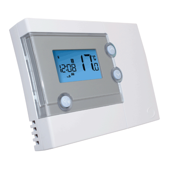
• R&TTE Directive 99/5/EC SAFETY INFORMATION These instructions are applicable to the Salus Controls model stated on the front cover of this manual only, and must not be used with any other make or model. These instructions are intended to apply in the United Kingdom only, and should be followed along with any other statutory obligations. - Page 3 The RT500 programmable room thermostat from Salus Controls is a stylish and accurate 5/2 or 7 day programmable electronic thermostat with a large, easy to read display. This programmable thermostat has been specifically designed to be used for both Volt Free and AC heating applications.
-
Page 4: Installation
If you are not sure how to install the Boiler Control consult either with a qualified electrician, heating engineer or your boiler / heating system supplier for advice on how to continue. RT500BC INSTRUCTION MANUAL... - Page 5 Recessed button for ID learning Max. ambient temperature 55°C Transmitter link via radio frequency Current rating 5A (resistive) @ 230V AC Connections: 1 - Neutral input 2 - Live input 3 - Common input 4 - Normally open output RT500BC INSTRUCTION MANUAL...
-
Page 6: Boiler Control Wiring Terminals
BOILER CONTROL WIRING TERMINALS Terminal Identifier Description Neutral Live feed (230V AC) Linked Live feed N.O. Switched Live (Normally Open [N.O.] contact) TYPICAL WIRING INSTALLATION Boiler Control Boiler RT500BC INSTRUCTION MANUAL... - Page 7 ± 0.5°C (factory default setting) or ± 1.0°C 1,2,3,4,5 Removable jumpers for altering the RF address code when used in conjunction with the teaching mode of the boiler control. NOTE: The Reset button must be pressed after changing jumper positions. RT500BC INSTRUCTION MANUAL...
- Page 8 Now insert the new batteries, insert bottom battery with the“+” end first followed by the top battery “ – “first . Note: When changing the batteries the RT500 will save your settings for 10 sec, after 10 seconds your settings will be lost RT500BC INSTRUCTION MANUAL...
- Page 9 To adjust the RF ID code of the RT500, remove one or more of the jumper caps located on the back of the unit (labelled 1 to 5 as shown in this picture): Then follow the steps below to resync the RF communication. RT500BC INSTRUCTION MANUAL...
-
Page 10: Synchronising Boiler Control
Boiler Control will store the new RF address code into its internal memory. The LED will flash twice if the code is stored correctly, or 4 times if this was unsuccessful. The Boiler Control will then exit pairing mode and the LED will go out. RT500BC INSTRUCTION MANUAL... - Page 11 RT500, check that the Boiler Control has a mains supply. If this isn’t the problem you can also alter the RF address code by following the ‘RF ID Code Setting’ section of this manual, and then repeat steps 1 to 5. RT500BC INSTRUCTION MANUAL...
- Page 12 LED indicator will also be lit constantly. The manual mode is only to be used as a temporary control if problems develop with the communication from the RT500. RT500BC INSTRUCTION MANUAL...
-
Page 13: After Installation
If the Reset Button is pressed, the RT500 will behave in the same way as described above, user settings stored in the internal memory will be deleted and overwritten with the default settings, and all programmable thermostat control settings will be returned to default values. RT500BC INSTRUCTION MANUAL... -
Page 14: User Interface
5 seconds, or activates / deactivates Frost Protection SELECT key Selects a clock or programme setting and enters learning mode SELECT SET key Sets a clock or programme setting RESET button Resets the programmable thermostat to default (original factory) settings RT500BC INSTRUCTION MANUAL... -
Page 15: Setting The Time
Press the SET key to confirm the new time and day settings. This will store the changes and return the RT500 to Normal mode. The RT500 will also return to Normal mode (and save the clock settings) if no keys are pressed for more than 15 seconds. RT500BC INSTRUCTION MANUAL... -
Page 16: 5/2 Day Mode
Normal mode. This will change the unit status to Programme Setting mode. The LCD display will display programme number 1 and SET PROG, with all other indicators cleared. The weekdays will be flashing to indicate they are the selected item and are ready to be adjusted: RT500BC INSTRUCTION MANUAL... - Page 17 Minutes Set point temperature Hour Minutes Set point temperature …before then allowing you to cycle back to Programme 1. Pressing the SET key at any time will confirm the setting and return to the programme set selection. RT500BC INSTRUCTION MANUAL...
-
Page 18: Day Mode
RT500 into Normal mode. Press the SELECT key to confirm the Day selection. Once this is set, the ‘Hour’ will flash to indicate that it is the selected item and is the next item to be adjusted: RT500BC INSTRUCTION MANUAL... - Page 19 Regardless of which programming mode the RT500 is set for (5/2 or 7 day), not pressing any keys for 15 seconds will automatically save any programming changes and exit to Normal mode. You can also review or change programme settings when Frost Protection is enabled. RT500BC INSTRUCTION MANUAL...
-
Page 20: Frost Protection
REVIEWING SET POINT TEMPERATURE You can view the set point temperature at any time by pressing either the UP or DOWN key. When any programme is running, the LCD display will show the programme set point temperature with indicator displayed: RT500BC INSTRUCTION MANUAL... -
Page 21: Temporary Override
In normal mode press and hold either the up or down key to display the set point temperature. After a few seconds the RT500 will enter temporary override mode and will allow increase or decrease of the set point temperature. RT500BC INSTRUCTION MANUAL... - Page 22 RT500 after 1 hour, the Boiler Control will turn off the boiler, and the LED indicator will flash constantly (two times every second). Once the Boiler Control receives a valid ON or OFF signal, the Boiler Control will control the heating system accordingly. RT500BC INSTRUCTION MANUAL...
-
Page 23: Reset Button
While in SLEEP mode: • The LCD display will be blank. • All output from the RT500 will be turned off immediately. Press any key to wake up the RT500 and exit SLEEP mode. RT500BC INSTRUCTION MANUAL... -
Page 24: Maintenance
If the RT500 is still not functioning correctly, press the Reset Button. WARRANTY Salus Controls warrants that this product will be free from any defect in materials or workmanship, and shall perform in accordance with its specification, for a period of two years from the date of installation. Salus Controls sole liability for breach of this warranty will be (at its option) to repair or replace the defective product. -
Page 25: Product Specification
21 ºC 8:00 AM 8:00 AM TEMP 14 ºC 21 ºC 4:00 PM 4:00 PM TEMP 21 ºC 21 ºC 6:00 PM 6:00 PM TEMP 21 ºC 21 ºC 10:00 PM 10:00 PM TEMP 14 ºC 14 ºC RT500BC INSTRUCTION MANUAL... - Page 26 Radio Frequency: 868 MHz Switching Voltage: 0-230V AC / 50Hz Switching Current: 5A resistive, 1A inductive Environment 0 º C to + 40 º C Operating Temperature: - 20 º C to + 60 º C Storage Temperature: RT500BC INSTRUCTION MANUAL...
- Page 27 RT500BC Warranty Salus Controls warrants that this product will be free from any defect in materials or workmanship, and shall perform in accordance with its specification, for a period of two years from the date of installation. Salus Controls sole liability for breach of this warranty will be (at its option) to repair or replace the defective product.
- Page 28 Email: sales@salus-tech.com Tel: 01226 323961 Sales Email: tech@salus-tech.com Tel: 01226 323961 Technical Salus Controls plc, Salus House, Dodworth Business Park South, Whinby Road, Dodworth, Barnsley S75 3SP...
Need help?
Do you have a question about the RT500BC and is the answer not in the manual?
Questions and answers