Salus RT510RF Installation Manual
Hide thumbs
Also See for RT510RF:
- Full user manual (26 pages) ,
- Quick manual (2 pages) ,
- Installation manual (22 pages)
Table of Contents
Advertisement
Quick Links
Advertisement
Table of Contents

Related Manuals for Salus RT510RF


Summary of Contents for Salus RT510RF
- Page 1 Model: RT510RF Installation Manual...
-
Page 2: Table Of Contents
DIP Switch Settings .................... 7 Button Functions ......................7 LCD Functions ......................... 8 Pairing procedure ......................8 Pair the RT510RF and RXRT510 ................ 8 Testing procedure ....................9 Installer Mode ......................... 10 Operations ......................... 11 Setting the time ......................11 Programming the RT510RF ................ -
Page 3: Product Compliance
Always isolate the AC Mains supply before installing or working on any components that require 230 VAC 50Hz supply. Box content Quick Guide Installation 2x screws and plugs 1x RT510TX 1x RXRT510 2x AA batteries 1x Thermostat Stand RT510RF Installation Manual... -
Page 4: Introduction
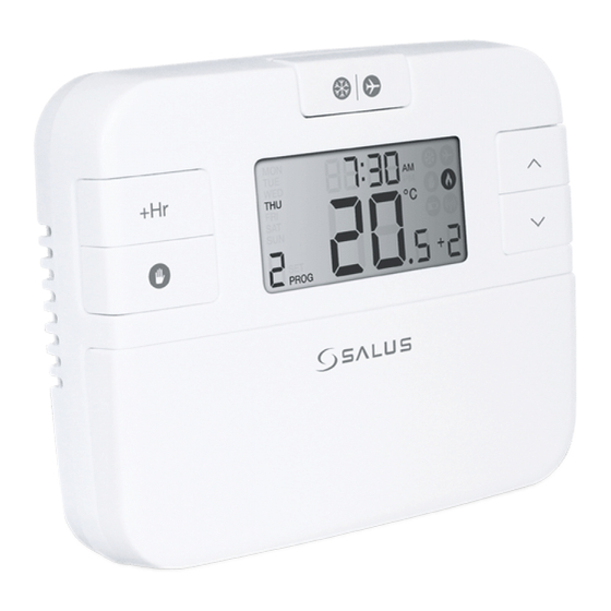
Nearby electric fires, televisions, wall or table lamps may prevent the thermostat from working properly. The RT510RF from SALUS Controls is a stylish and accurate 5/2 or 24h programmable electronic thermostat with a large, easy to read Liquid Crystal Display (LCD). This programmable thermostat has been specifically designed to be used for both Volt Free and AC heating applications. -
Page 5: Features
Unscrew the backplate of the RXRT510 receiver in order to do the wiring connections. After that please switch the receiver ON. AUTO MANUAL Terminal Description Receiver Terminals Switch Terminal Common Switch Terminal Mains Live (230VAC) Mains Neutral Electrical diagram RT510RF Installation Manual... -
Page 6: Button Description For Rxrt510 Receiver
Time: 6:00pm PROG indicator Setpoint Temp: 21.0°C Setpoint Temp: 21.0°C Frost Protection indicator Time: 10:00pm Time: 10:00pm Heat indicator Setpoint Temp: 14.0°C Setpoint Temp: 14.0°C Low-Battery Warning indicator Off, to be renewed within 5 seconds Output Relay 06 RT510RF Installation Manual... -
Page 7: Dip Switch Settings
SELECT Press to confirm your settings 1. Press once to enter in Test Mode for RT510RF 2. Press for 3 seconds to enter/exit Pairing Mode for RT510RF Press the buttons for 3 seconds to enter Installer Mode SELECT Press the buttons for 3 seconds to enter Clock Settings... -
Page 8: Lcd Functions
Holiday Mode ON Current program Pair the RT510RF and RXRT510 Please make sure that the thermostat and the receiver are paired. In order to do this you can use the Pairing or the testing procedure. The Testing procedure will allow you to check if the devices are communicating between them. -
Page 9: Testing Procedure
3 Sec TEST / PAIRING SELECT TEST / PAIRING SELECT Testing procedure AUTO MANUAL TEST / PAIRING 1 Sec SELECT AUTO MANUAL TEST / PAIRING SELECT RT510RF Installation Manual... -
Page 10: Installer Mode
SELECT SELECT 3 Sec 3 Sec Press and hold all three buttons together for 3 sec °C RESET RESET SELECT SELECT Press Set in order to Press Up/Down to select changed the setting. the desired value. 10 RT510RF Installation Manual... -
Page 11: Operations
Operations The RT510RF is configured and adjusted by the use of a minimal number of user controls, and an intuitive user interface. The Backlight Liquid Crystal Display (LCD) gives a highly visible, easily readable indication of the programmable thermostat status. -
Page 12: Programming The Rt510Rf
Press Up or Down to select Weekday Weekend or the Day for which you want to create the program RESET RESET SELECT SE LECT Press Select to confirm your option. Press Up/Down to set the hour. 12 RT510RF Installation Manual... - Page 13 Main Screen. Note: Don’t forget to move the DIP Switch to 24h in order to have the individual programme active. After that please follow the same instructions as for the 5-2 days programme. RT510RF Installation Manual...
-
Page 14: Functions
Press Up/Down to the setpoint temperature. set the temperature. Note: To exit the temporary override procedure, you can wait for 3 seconds until the set temperature stops flashing or you can press on the SET button once. 14 RT510RF Installation Manual... -
Page 15: Permanent Override
Setpoint temperature. See below the explanations for the Boost Mode settings that are available for each of the modes set on the thermostat. Please follow the one that suits you needs: RT510RF Installation Manual... -
Page 16: Boost Function In Normal Mode
Main screen. Note: RT510RF will work in Boost Mode for up to 9 hours, set on the desired temperature. After the Boost time is over, the thermostat will return to Normal Mode and will follow the schedule created by you. -
Page 17: Boost Function In Temporary Override Mode
Set to save your options and to return to main screen. Note: RT510RF will work in Boost Mode for up to 9 hours, set on the desired temperature. After the Boost time is over, the thermostat will return to the Permanent Override Mode. -
Page 18: Boost Function In Frost/Holiday Mode
Frost setpoint then the thermostat will automatically change to Frost mode ON. Follow the steps below for setting up the Frost Mode. RESET RESET SELECT SELECT Press the once for turning the Frost protection ON. 18 RT510RF Installation Manual... -
Page 19: Holiday Function
Follow the steps below in order to set the Holiday Mode. 3 sec RESET RESET SELECT SELECT Press the for 3 sec to turn the Press Up/Down to set the Holiday Holiday Mode ON. period. *Max 31 days RT510RF Installation Manual... -
Page 20: Other Functions
Sleep Mode By pressing both the UP and DOWN keys together, the RT510RF will enter SLEEP mode. In this mode, all the RT510RF functions will be paused to save battery power, with the exception of the clock which will continue to run in the background. -
Page 21: Reset Function
Permanent and temporary Frost Protection 5ºC Adjustable Power Source 230V AC 50Hz for RXRT510 and 2xAA batteries for RT510TX Temperature Scale 5 to 35ºC Device Parameters See page 9 Operating Temperature 0 to 40ºC Storage Temperature -20 to 60ºC RT510RF Installation Manual... -
Page 22: Warranty
Warranty SALUS Controls warrants that this product will be free from any defect in materials or workmanship, and shall perform in accordance with its specification, for a period of two years from the date of installation. SALUS Controls sole liability for breach of this warranty will be (at its option) to repair or replace the defective product. - Page 23 SALUS Controls is a member of the Computime Group Maintaining a policy of continuous product development, SALUS Controls plc reserves the right to change specification, design and materials of products listed in this brochure without prior notice. For the latest PFD Instruction Manual, go to www.salus-manuals.com...
Need help?
Do you have a question about the RT510RF and is the answer not in the manual?
Questions and answers