Advertisement
Table of Contents
- 1 Full Power
- 2 Unpacking Instructions
- 3 General Information
- 4 Safety Interlock
- 5 Driving Power
- 6 Filament Supply
- 7 Export Modifications
- 8 Metering Functions
- 9 Technical Assistance
- 10 Periodic Maintenance
- 11 Transformer Installation
- 12 Tube Installation
- 13 Power Connections
- 14 Tuning Instructions
- 15 Parts List
- Download this manual
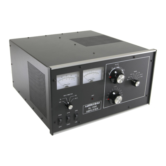
The Ameritron AL-1500 is a 1500 watt output linear amplifier that
operates from 160 through 15 meters. The Ameritron AL-1500X is the
export model and covers 160 through 10 meters. The AL-1500J is the
export model for Japan and covers 160 through 10 meters. The AL-1500
uses a single 3CX1500A7/8877 tube in a class AB2 grounded grid circuit.
CW, FM and RTTY efficiency is improved by shifting the bias deeper into
class B. The heavy duty power supply and RF components, combined with
a forced air system utilizing a chimney, provide long service life for
expensive components. The AL-1500 is shipped factory wired for 240
volt, 50/60 Hz power mains.
PLEASE READ THIS MANUAL BEFORE OPERATING THIS EQUIPMENT!
AMERITRON AL-1500
FULL POWER
LINEAR AMPLIFIER
INSTRUCTION MANUAL
116 Willow Rd.
Starkville, MS 39759
Advertisement
Table of Contents

Related Manuals for AMERITRON AL-1500


Summary of Contents for AMERITRON AL-1500
-
Page 1: Full Power
160 through 15 meters. The Ameritron AL-1500X is the export model and covers 160 through 10 meters. The AL-1500J is the export model for Japan and covers 160 through 10 meters. The AL-1500 uses a single 3CX1500A7/8877 tube in a class AB2 grounded grid circuit. -
Page 2: Unpacking Instructions
Inspect each item for visible damage. If any damage occurred during shipment, notify the transportation company immediately. 2. Save all packing materials in case you need to return your AL-1500(X/J) for factory service. The cartons have been designed to give maximum protection for this amplifier. - Page 3 FEATURES proper operation of the amplifier. The other meter reads 1. High performance tube: the AL-1500 uses a single rugged Plate Voltage (HV), Plate Current (IP), Peak RF Watts 3CX1500A7/8877 tube. (PO) and ALC. 2. High power gain: the 3CX1500A7/8877 features high power gain.
-
Page 4: General Information
TIMER OVERLOAD BOARD DRIVING POWER The AL-1500 has a circuit board mounted on the front panel side of the filter capacitor board that provides time delay to insure the cathode of the 3CX1500A7/8877 has reached proper... -
Page 5: Metering Functions
METERING FUNCTIONS R5 on the Meter Board (50-01140-1) adjusts the calibration of the The AL-1500 has two illuminated meters. The Grid Current meter power meter. provides a continuous indication of the 3CX1500/8877 grid current. This exclusive feature of Ameritron amplifiers indicates proper amplifier operation better than any other parameter. -
Page 6: Tube Installation
ONLY. Do not "rock" or VAC. The Standard USA voltage is 240 VAC, not 220. "twist" the tube. Also the chimney is already mounted inside the AL-1500 amplifier. After the tube is installed, attach the anode connector as follows: (Refer to the Fig. 4) . - Page 7 FILAMENT/BLOWER WIRING INSTRUCTIONS The AL-1500 and 1500(X) amplifiers come prewired for 240V line voltage and with the blower prewired for medium high fan speed. NOTE: The AL-1500J Japanese export model is prewired for 208V line voltage. This page gives filament transformer connection details for various line voltages and blower speeds.
- Page 8 100mA of current when pulled to ground. 1. Connect the RF output of the exciter to the RF IN connector on the rear of the AL-1500 with 50 ohm coax. Use any good 4. Connect a short ground lead from a good earth and RF ground quality 50 ohm cable long enough to connect the amplifier to to the GND terminal.
-
Page 9: Power Connections
INSTALLATION Cont. LOCATION POWER CONNECTIONS The AL-1500 is supplied with a NEMA 6-15P plug for 240V -Do not operate the Amplifier in excessively warm locations AC operation. Operation with power main voltages below or near heating vents or radiators. Be sure air can circulate 200 volt is not recommended. - Page 10 SSB position. Plate current should now read 250 mA. Return the CW-SSB switch to the CW position. Set the AL-1500 front panel switches as follows: POWER TO OFF Note: The no drive currents will vary up to 25% due to OPR-STBY TO STBY component and line voltage tolerences.
- Page 11 AL-1500 will tolerate is approximately 100 watts. At this drive PROCEDURE". level the output of the AL-1500 may be in excess of 2000 watts when properly tuned. The ALC should be connected and 1. Place the SSB-CW switch in the SSB position.
-
Page 15: Parts List
PARTS LIST...
Need help?
Do you have a question about the AL-1500 and is the answer not in the manual?
Questions and answers
parts. The light bulks on my meter have 2 out. Can I get replacements?
Yes, the replacement light bulb for the AMERITRON AL-1500 meter is a 12V meter lamp with part number 420-0164.
This answer is automatically generated