Table of Contents
Advertisement
Quick Links
Download this manual
See also:
User Manual
Advertisement
Table of Contents

Related Manuals for Moxa Technologies PowerTrans PT-G7509 Series


Summary of Contents for Moxa Technologies PowerTrans PT-G7509 Series
-
Page 1: Hardware Installation Guide
Moxa PowerTrans Switch PT-G7509 Series Hardware Installation Guide Fourth Edition, June 2010 © 2010 Moxa Inc. All rights reserved. Reproduction without permission is prohibited. Fl.4, No.135, Lane 235, Pao-Chiao Rd. Shing Tien City, Taipei, Taiwan, R.O.C. TEL: +886-2-8919-1230 P/N: 1802075090013... - Page 2 Package Checklist The Moxa PowerTrans switch is shipped with the following items. If any of these items are missing or damaged, please contact your customer service representative for assistance. 1 Moxa PowerTrans Switch Hardware Installation Guide CD-ROM with User’s Manual and SNMP MIB file...
-
Page 3: Rack Mounting
WARNING Safety First! Be sure to disconnect the power cord before installing and/or wiring your Moxa PowerTrans Switch. Calculate the maximum possible current in each power wire and common wire. Observe all electrical codes dictating the maximum current allowable for each wire size. -
Page 4: Wiring The Power Inputs
Wiring the Power Inputs The PT series of switches supports dual redundant power supplies: “Power Supply 1 (PWR1)” and “Power Supply 2 (PWR2)”. The connections for PWR1, PWR2 and the RELAY are located on the terminal block. The front view of the terminal block connectors are shown below. -
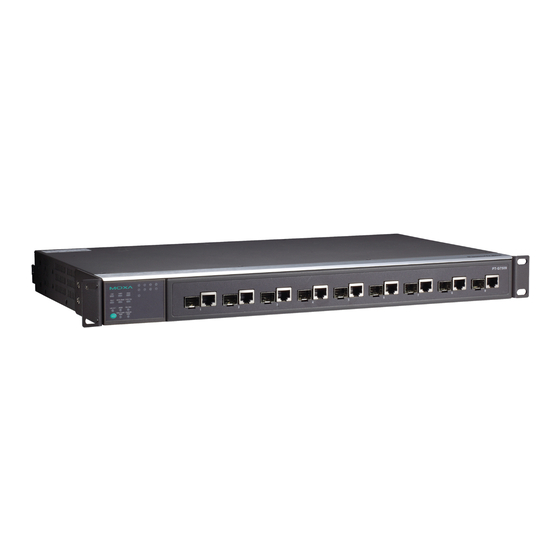
Page 5: Led Indicators
LED Indicators The front panel of the PT switch contains several LED indicators. The function of each LED is described in the table below. Color State Description System LEDs System has passed self-diagnosis test on boot-up and is ready to run. GREEN System is undergoing the STAT... -
Page 6: Specifications
The corresponding module port’s Blinking data is being transmitted. The corresponding module port’s link is inactive. The corresponding module port’s data is being transmitted at 10 Mbps. The corresponding module port’s data is being transmitted at 100 SPEED GREEN Mbps. The corresponding module port’s Blinking data is being transmitted at... - Page 7 Storage Temp. -40 to 85°C (-40 to 185°F) Ambient Relative 5 to 95% (non-condensing) Humidity. 5 years Warranty Technical Support Contact Information www.moxa.com/support Moxa Americas: Moxa China (Shanghai office): Toll-free: 1-888-669-2872 Toll-free: 800-820-5036 Tel: +1-714-528-6777 Tel: +86-21-5258-9955 Fax: +1-714-528-6778 Fax:...
Need help?
Do you have a question about the PowerTrans PT-G7509 Series and is the answer not in the manual?
Questions and answers