Table of Contents
Advertisement
Quick Links
PT-G503-PHR-PTP Series
Quick Installation Guide
Moxa Managed PRP/HSR Redundancy Box
Moxa Americas:
Toll-free: 1-888-669-2872
Tel:
1-714-528-6777
Fax:
1-714-528-6778
Moxa Europe:
Tel:
+49-89-3 70 03 99-0
Fax:
+49-89-3 70 03 99-99
Moxa India:
Tel:
+91-80-4172-9088
Fax:
+91-80-4132-1045
Edition 2.0, April 2017
Technical Support Contact Information
www.moxa.com/support
2017 Moxa Inc. All rights reserved.
Moxa China (Shanghai office):
Toll-free: 800-820-5036
Tel:
+86-21-5258-9955
Fax:
+86-21-5258-5505
Moxa Asia-Pacific:
Tel:
+886-2-8919-1230
Fax:
+886-2-8919-1231
P/N: 1802005030011
*1802005030011*
Advertisement
Table of Contents

Related Manuals for Moxa Technologies PT-G503-PHR-PTP Series


Summary of Contents for Moxa Technologies PT-G503-PHR-PTP Series
- Page 1 PT-G503-PHR-PTP Series Quick Installation Guide Moxa Managed PRP/HSR Redundancy Box Edition 2.0, April 2017 Technical Support Contact Information www.moxa.com/support Moxa Americas: Moxa China (Shanghai office): Toll-free: 1-888-669-2872 Toll-free: 800-820-5036 Tel: 1-714-528-6777 Tel: +86-21-5258-9955 Fax: 1-714-528-6778 Fax: +86-21-5258-5505 Moxa Europe: Moxa Asia-Pacific:...
-
Page 2: Package Checklist
24/48 VDC or 110/220 VDC/VAC power supply ranges to increase the reliability of the power supply. Package Checklist The Moxa PT-G503-PHR-PTP series products are shipped with the following items. If any of these items are missing or damaged, please contact your customer service representative for assistance. -
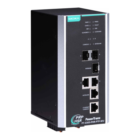
Page 3: Panel Layout
Panel Layout 1. Power input PWR1/PWR2 LED 2. State LED / Fault LED 3. PRP/HSR/QUADBOX/COUPLING 4. A/B port LED 5. Ethernet console port LED 6. INTERLINK port LED 7. 10/100/1000BaseT(X) A/B port and interlink port or 100/1000BaseSFP slot combo ports 8. -
Page 4: Mounting Dimensions (Unit = Mm (Inch))
Mounting Dimensions (unit = mm (inch)) DIN-Rail Mounting The metal DIN-rail kit is fixed to the back panel of the PT-G503-PHR-PTP when you take it out of the box. Mount the PT-G503-PHR-PTP on corrosion-free mounting rails that meet the EN 60715 standard. - 4 -... -
Page 5: Installation
Installation STEP 1: Insert the upper lip of the DIN-rail into the DIN-rail mounting kit. STEP 2: Press the PT-G503-PHR-PTP towards the DIN-rail until it snaps into place. Removal STEP 1: Pull down the latch on the mounting kit with a screwdriver. STEP 2 &... -
Page 6: Wiring Requirements
STEP 2: Mounting the PT-G503-PHR-PTP to a wall requires 6 screws. Use the PT-G503-PHR-PTP, with wall mount plates attached, as a guide to mark the correct locations of the 6 screws. The heads of the screws should be less than 6.0 mm in diameter, and the shafts should be less than 3.5 mm in diameter, as shown in the figure at the right. - Page 7 Grounding the PRP/HSR Redundancy Box Grounding and wire routing help limit the effects of noise due to electromagnetic interference (EMI). Run the ground connection from the ground screw to the grounding surface prior to connecting devices. ATTENTION This product is intended to be mounted to a well-grounded mounting surface, such as a metal panel.
-
Page 8: Wiring The Digital Inputs
ATTENTION Before connecting the PT-G503-PHR-PTP to the DC power inputs, make sure the DC power source voltage is stable. Wiring the Digital Inputs The PT-G503-PHR-PTP has one digital input, DI 1. The DI consists of two contacts from the 5-pin terminal block connector on the PT-G503-PHR-PTP’s bottom panel. - Page 9 10/100/1000BaseT(X) Ethernet Port Connection The 10/100/1000BaseT(X) ports located on the front panel are used to connect to Ethernet-enabled devices. Most users will choose to configure these ports for Auto MDI/MDI-X mode, in which case the port’s pinouts are adjusted automatically depending on the type of Ethernet cable used (straight-through or cross-over), and the type of device (NIC-type or HUB/Switch-type) connected to the port.
-
Page 10: Usb Console Connection
100Base-FX or 1000Base-X SFP Fiber Port The Gigabit Ethernet ports on the PT-G503-PHR-PTP are SFP slots, which require 100Base-FX/1000Base-X or Gigabit mini-GBIC fiber transceivers to work properly. Moxa provides complete transceiver models for various distance requirements. Multi-mode: 1000BaseSX 0 to 550 m, 850 nm (50/125 μm, 400 MHz x km) 0 to 275 m, 850 nm (62.5/125 μm, 200 MHz x km) 1000BaseLX 0 to 1100 m, 1310 nm (50/125 μm, 800 MHz x km) -
Page 11: Restore Factory Defaults Button
ABC-02-USB Installation Plug the ABC-02-USB into the PT-G503-PHR-PTP’s USB storage port. If you would like to secure the ABC-02-USB to the wall, we suggest using an M4 screw. USB Storage Port (Type A Connector) Pinouts Description VCC (+5V) D- (Data-) D+ (Data+) GND (Ground) Restore Factory Defaults Button... -
Page 12: Specifications
Color State Description 1. System has failed, or is under quick inspection 2. The relay signal contact is open FAULT 3. ABC-02 loading/saving failure The system is operating normally PRP is working Green PRP is not enabled HSR is working Green HSR is not enabled QuadBox function is working... -
Page 13: Restricted Access Locations
Physical Characteristics Housing Aluminum alloy, IP40 protection Dimensions 80 x 160 x 110 mm (3.15 x 6.30 x 4.33 in) Weight 1210 g (2.69 lb) Installation DIN-rail mounting Environmental Limits Operating Temperature -40 to 85°C (-40 to 185°F) Storage Temperature -40 to 85°C (-40 to 185°F) Ambient Relative 5 to 95% (non-condensing)
Need help?
Do you have a question about the PT-G503-PHR-PTP Series and is the answer not in the manual?
Questions and answers