Moxa Technologies PT-G7728 Series Quick Installation Manual
Hide thumbs
Also See for PT-G7728 Series:
- Quick installation manual (16 pages) ,
- User manual (122 pages) ,
- User manual (123 pages)

Related Manuals for Moxa Technologies PT-G7728 Series


Summary of Contents for Moxa Technologies PT-G7728 Series
- Page 1 PT-G7728/G7828 Series Quick Installation Guide Version 2.1, October 2023 Technical Support Contact Information www.moxa.com/support 2023 Moxa Inc. All rights reserved. P/N: 1802077280416 *1802077280416*...
-
Page 2: Package Checklist
Package Checklist Moxa’s PT-G7728/G7828 industrial rackmount switch is shipped with the following items. If any of these items are missing or damaged, please contact your customer service representative for assistance. • 1 PT-G7728 or G7828 switch • 2 protective caps for unused ports, 3 protective caps for unused USB ports •... -
Page 3: Ethernet Modules
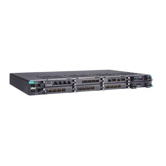
Rear Panel 1. Console port (RJ45, RS-232) 2. USB storage port 3. System LED indicators 4. Module and port LED indicators 5. Reset button Dimensions Unit: mm (inches) Ethernet Modules LM-7000H-4GTX LM-7000H-4TX LM-7000H-4GSFP LM-7000H-4GPoE LM-7000H-4PoE LM-7000H-2GPHR - 3 -... -
Page 4: Power Modules
High-Availability Seamless Redundancy (HSR) and Parallel Redundancy (PRP) protocols. To use this module, the PT-G7728 switch must have Firmware V6.2 or higher. NOTE The LM-7000H-2GPHR module is only supported in slot 5 of the PT-G7728 Series. Power Modules PWR-HV-P48 PWR-LV-P48 PWR-HV-NP... - Page 5 AWG and the thread diameter should be at least 3.5 mm. Particular attention should be given to supply connections other than direct connections to the branch circuit (e.g., use of power strips). NOTE The rackmount ears can be installed on the front or rear of the PT-G7728/G7828 switch.
-
Page 6: Wiring Requirements
Wiring Requirements WARNING Do not disconnect modules or wires unless power has been switched off or the area is known to be non-hazardous. The device may only be connected to the supply voltage printed next to the power input. The device is designed for operation with a Safety Extra-Low Voltage (SELV) or an isolated power supply, which means that they may only be connected to the supply voltage connections and to the signal contact with a... -
Page 7: Wiring The Relay Contact
NOTE The reverse power input connection will not activate the device or PoE input. In addition, the PoE will only activate when the system power input is installed on the same power unit. Wiring the Relay Contact Each power module has one relay output that can provide two types of relay output. -
Page 8: Console Port Connection
The removal procedure is as follows: 1. Loosen the 2 screws of the module. 2. Pull the module out of the slot. 3. Insert the dummy module into the slot to have better protection against dust and EMI. 4. Fasten the dummy module using 2 screws. The tightening torque is 4 kgf-cm (0.40 Nm) NOTE If one of the modules is removed from the device, it is advisable to insert a dummy module to provide better... -
Page 9: The Reset Button
The Reset Button The reset button can perform two functions. One is to reset the PT- G7728/G7828 switch back to factory default settings and the other is to perform a quick back up of configuration and log files to the ABC-02- USB automatic backup configurator. - Page 10 Color State Description System is in normal operation PTP function is enabled Amber The device is starting to receive the sync SYNC Blinking packet Green The PTP function has successfully converged 1. This switch is set as the Master of the Turbo Ring, or as the Head of the Turbo Chain.
-
Page 11: State Description
PT-G7728/G7828 (Rear Panel view) Color State Description System LEDs System has passed self-diagnosis test on boot up and is ready to run 1. When the reset button is pressed for 5 seconds, the LED will blink continuously (1 Green time/s) until the device is reset to the Blinking factory default. - Page 12 Color State Description Power is being supplied to the main module’s power input PWR1 PWR1 Amber Power is not being supplied to the main module’s power input PWR1 Power is being supplied to the main module’s power input PWR2 Pulsate The unit in the power 2 is acting as a slave PWR2 Amber Slowly...
- Page 13 Color State Description The port's 100 Mbps link is active. Green Blinking Data is transmitting at 100 Mbps. Ports The port's 10 Mbps link is active. 1 to 4 Amber Blinking Data is transmitting at 10 Mbps. The port's link is inactive. LM-7000H-4GSFP Color State...
- Page 14 Color State Description The external power supply is not working for PoE+ power output The port's 100 Mbps link is active Green Blinking Data is transmitting at 100 Mbps Ports The port's 10 Mbps link is active 1 to 4 Amber Blinking Data is transmitting at 10 Mbps The port's link is inactive...
-
Page 15: Specifications
PWR-HV-NP/PWR-LV-NP Color State Description Normal operation. Amber No power supply. Specifications Technology Standards IEEE 802.3af/at for Power-over-Ethernet IEEE 802.3 for 10BaseT IEEE 802.3u for 100BaseT(X) and 100BaseFX IEEE 802.3ab for 1000BaseT(X) IEEE 802.3z for 1000BaseX IEEE 802.3x for Flow Control IEEE 802.1D-2004 for Spanning Tree Protocol IEEE 802.1w for Rapid STP IEEE 802.1s for Multiple Spanning Tree Protocol... - Page 16 Power Requirements PWR-HV-P48: Input Voltage (110/220 VDC), (110 VAC, 60 Hz), (220 VAC, 50 Hz), PoE: 48 VDC, 8 A (53 to 57 VDC is recommended of PoE+ device) PWR-LV-P48: 24/48 VDC, PoE: 48 VDC, 8 A (53 to 57 VDC is recommended of PoE+ device) PWR-HV-NP: (110/220 VDC), (110 VAC, 60 Hz), (220 VAC, 50 Hz)
-
Page 17: Warranty
Physical Characteristics Housing IP30 protection Dimensions 443 x 44 x 280 mm (17.32 x 1.37 x 11.02 in) Weight PT-G7728/G7828: 3.08 kg (6.78 lb) LM-7000H-4GSFP: 0.30 kg (0.66 lb) LM-7000H-4GTX: 0.24 kg (0.53 lb) LM-7000H-4TX: 0.24 kg (0.53 lb) LM-7000H-4GPoE: 0.31 kg (0.69 lb) LM-7000H-4PoE: 0.31 kg (0.69 lb) LM-7000H-2GPHR: 0.31 kg (0.69 lb) PWR-HV-P48/PWR-LV-P48: 0.36 kg (0.79 lb)
Need help?
Do you have a question about the PT-G7728 Series and is the answer not in the manual?
Questions and answers