Table of Contents
Advertisement
WARNING! Please read this entire manual before installation and use of the Bixby MaxFire
Room Heater. Failure to follow these instructions could result in property damage, bodily injury or even death.
Contact local building officials, fire officials or the authority having jurisdiction about restrictions, permits and
installation inspection requirements in your area.
MODEL
_______________
DATE PURCHASED _______________
Installation, Operating and Maintenance
Instructions
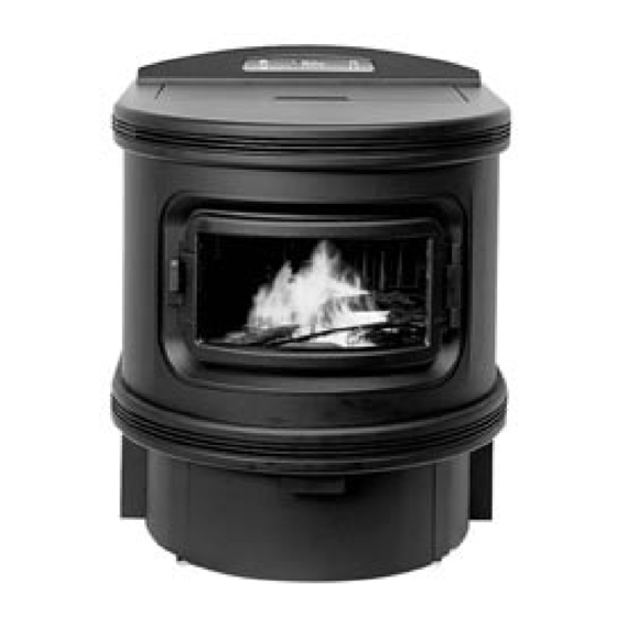
MaxFire
Multi-Fuel Room Heater
TM
Save these instructions for future reference.
PLEASE RECORD THE FOLLOWING INFORMATION:
DEALERSHIP
DEALER PHONE _______________ INSTALLER PHONE _______________
SERIAL NUMBER
Bixby Energy Systems
www.bixbyenergy.com
_______________ INSTALLER
____________________________
877-500-2800
Multi-Fuel
TM
_______________
Advertisement
Table of Contents

Subscribe to Our Youtube Channel
Related Manuals for Bixby Energy MaxFire


Summary of Contents for Bixby Energy MaxFire
- Page 1 Instructions MaxFire Multi-Fuel Room Heater WARNING! Please read this entire manual before installation and use of the Bixby MaxFire Multi-Fuel Room Heater. Failure to follow these instructions could result in property damage, bodily injury or even death. Contact local building officials, fire officials or the authority having jurisdiction about restrictions, permits and installation inspection requirements in your area.
-
Page 3: Table Of Contents
TABLE OF CONTENTS Safety Information Minimum Clearances to Combustible Materials Specifications Planning the Installation Performing the Installation Optional Thermostat Operation Leveling the Room Heater Venting Installation and Instructions Vent System Approvals Venting Components Inspections Permits Vent Maintenance Vent Location Location of Exhaust General Vent Installation Instructions Log Placement Instructions Operating Instructions... -
Page 4: Safety Information
SAFETY INFORMATION Install and use only in accordance with these installation and operating instructions, page 9. Contact local building officials, fire officials, or the authority having jurisdiction about restrictions, permits, and inspection requirements in your area. Refer to instructions and local codes for precautions required for passing the vent pipe through a combustible wall or ceiling. -
Page 5: Minimum Clearances To Combustible Materials
MINIMUM CLEARANCES TO COMBUSTIBLE MATERIALS Floor Protector Free Standing and Alcove (rear only) Installation Clearances: 10.5” (267mm) 6” (150mm) 2” (50mm) 3” (75mm) 12” (305mm) NOTE: Minimum clearances are for temperature concerns and do not allow for enough room for maintenance. Please allow enough room on the sides for routine maintenance, 6”... -
Page 6: Specifications
Fuel Hopper Capacity: 2.4 cu. ft. (approx. 106 lbs. shelled corn) Listing: The Bixby MaxFire Multi-Fuel Room Heater was tested by OMNI-Test Laboratories, Beaverton, Oregon to ASTM E1509 and ULC C1482 (report number 223-S-06-2). Emission tests were also conducted per the USA Environmental Protection test methods 28A and 5G for particulate emissions. -
Page 7: Mobile Home Installation
IMPORTANT: Proper material handling equipment must be available to safely transport and position the Bixby Room Heater. Remove the protective packaging, using appropriate tools, and detach the unit from its shipping pallet. The Room Heater is attached to the pallet with two bolts. Remove the side pannels to gain access to the bolts. -
Page 8: Planning The Installation
To assure safe operation, it is absolutely essential that a floor protective device of metal or other non-combustible material be in place beneath the Room Heater. Note drawing below to determine dimensions the size of the mat. Lightweight, properly sized hearth pads are available from Bixby Energy Systems in colors to match your Room Heater. -
Page 9: Optional Thermostat Operation
OPTIONAL THERMOSTAT OPERATION The Room Heater is designed so that it can be operated by a wall mounted thermostat. This option is not provided directly from the factory, but can be purchased from your dealer or the Bixby website (www.bixbyenergy.com) or any other “on/off”... -
Page 10: Leveling The Room Heater
LEVELING THE ROOM HEATER CAUTION: THE ROOM HEATER SHOULD BE LEVELED BEFORE ATTACHING THE VENT PIPE. The supplied bulls eye level can be used to level the Room Heater front-to-back and side-to-side, a 6 in. level may also be used. Place the level centered side-to-side and about 4 in. -
Page 11: Venting Installation And Instructions
NEVER INSTALL SINGLE-WALL PIPE TO THE Room Heater. NOTE: Proper planning for your vent installation will result in greater safety, efficiency, and convenience, saving both time and money. Use only authorized BIXBY ENERGY SYSTEMS, INC. listed parts. Do not install damaged parts. TOOLS AND EQUIPMENT... -
Page 12: Venting Components
In case of fire, shut off appliance and call your Fire Department. Do not use the appliance or vent until it has been inspected for possible damage. • Due to the nature of solid fuels and their production of ash, Bixby Energy Systems is not responsible for flue by-products that might discolor roofs or walls. 2020866 REV A... -
Page 13: Vent Location
VENT LOCATION When exiting through walls, make sure NFPA rules are followed for distance from windows and openings. NOTE: The termination cap will be HOT during operation. Consider it’s proximity to doors or other traffic areas. 10ft 12 in 3 ft. 3 ft. -
Page 14: Location Of Exhaust
Bixby recommends not installing a venting system in a pipe chase or permanent wall structure. Vent pipe should be accessible for annual inspection and maintenance. Because solid fuel produces ash, Bixby Energy Systems is not responsible for flue by-products that might damage or discolor building structures (walls, floors, roofs, etc.). - Page 15 VENTING CONFIGURATIONS The allowable venting configuration is to be 25 equivalent horizontal feet (7.5 m) or less as determined through the following table: Type of Pipe Factor (ft) Total 90 deg elbow 5 (1.5m) 45 deg elbow 3 (0.9m) Horizontal Pipe 2 (0.6m) Vertical Pipe 0.5 (0.15m)
-
Page 16: General Vent Installation Instructions
GENERAL VENT INSTALLATION INSTRUCTIONS Follow the Room Heater manufacturer’s instructions and safety manual for maximum efficiency and safety. Connect only BIXBY ENERGY SYSTEMS DIRECT VENT to BIXBY ROOM HEATERS. CAUTION: Connect only one flue per appliance. Do not install a flue damper in the exhaust venting system of this unit. - Page 17 VERTICAL INTERIOR INSTALLATION NOTE: Vertical exterior installation is not recommended due to excessive condensation. NOTE: Bixby recommends not installing a venting system in a pipe chase or permanent wall structure (other than to exit the room using the Wall Thimble). Vent pipe should be accessible for annual inspection and maintenance.
- Page 18 HORIZONTAL THROUGH-THE-WALL-INSTALLATION The flue exit is on back of the Room Heater, and if a horizontal through-the- wall installation is desired: Place the Room Heater according to installation instructions. See Thimble Figure 7 for vent locations. 6”-12” 15-30cm Starter Locate vent termination per the NFPA rules. See Figure 7 (page 11). Collar Cut and frame a 10 in.
- Page 19 INSTALLATION IN A CATHEDRAL CEILING Mark a line on the side of the Cathedral Ceiling Support Box to correspond to the line of the roof pitch. Allow for the Support Box to protrude below the finished ceiling a minimum of 2 in (5 cm). See Figure 18. Position the appliance at its proper location on the floor.
- Page 20 INSTALLATION IN A CATHEDRAL CEILING (CONT.) Place the Vertical Support Clamp (5000576), around the top of the hole in the bottom of the Support Box. See Figure Connect the necessary amount of pipe sections to reach the Room Heater at a point where the Vent Cap will extend a minimum of 36 in (91 cm) above the roof.
- Page 21 CONNECTING TO EXISTING CLASS A CHIMNEY EITHER 6” OR 8” Due to cleaning, inspection and condensation issues, Bixby no longer recomends connecting the Room Heater to an existing Class A chimney. INSTALLATION THROUGH THE SIDE OF A MASONRY CHIMNEY Due to cleaning, inspection and condensation issues, Bixby no longer recomends connecting the Room Heater to an existing masonry chimney.
-
Page 22: Log Placement Instructions
LOG PLACEMENT INSTRUCTIONS The use of the logs provided with the Room Heater is optional. Locate the log box and remove the three logs. See Figure 23. Figure 23 Place one of the “Y” logs on the right side of the burn pot with the small end pointing towards the back of the firebox. -
Page 23: Operating Instructions
OPERATING INSTRUCTIONS FUEL It is strongly recommended that only Dry Shelled Corn (whole kernels), Wood Pellets (recommended maximum size approximately ¼ in (6mm) diameter x 1 ¼ in (32mm) long), Bixby Certified Corn or approved pelletized biomass fuel be used in this Room Heater (Up to 8,700 BTU’s per pound). When using Dry Shelled Corn, clean corn (free of foreign material like cobs, twigs, stones, etc.) with moisture level around 14% or less is recommended. -
Page 24: Start Up
START UP NOTE: It is recommended that all gold or silver plated surfaces of the Bixby Room Heater be cleaned with a mild glass cleaner before initial startup. NOTE: Use of a surge protector is recommended but not required for heater operation. CAUTION: Operate the Bixby Room Heater only with the Fuel Hopper Door closed. -
Page 25: Flashing Indicator Light System
FLASHING INDICATOR LIGHT SYSTEM The 8 heat level indicator lights on the Bixby Room Heater are also designed to act as potential problem indicators. Whenever one of these lights begins to flash, consult the chart below for reason and recommended solution. Light #1 Power failure during Room Heater operation: Push the “Off”... -
Page 26: Maintenance And Cleaning Procedures
MAINTENANCE AND CLEANING PROCEDURES The Bixby Room Heater has been designed to reduce the frequency of cleaning. However, if the simple maintenance tasks detailed below are not performed - the Room Heater will not run properly and will lead to reduced heating efficiency, increased operational problems and potential harm to its components. -
Page 27: Heat Exchanger Tubes
The ash drawer should be checked / emptied after burning approximately 100-200 lbs. (1 - 2 full hoppers) of fuel. Actual frequency will vary with usage, check every few days. Ashes should be placed in a metal container with a tight- fitting lid. -
Page 28: Cleaning The Exhaust Manifold
EXHAUST FAN CAUTION: Unplug the Room Heater from its power source before cleaning the impeller. To access this component, open Right Side Panel, and remove the fan cover. Using a brush and a vacuum, clean the impeller. Inspect gasket. If it is torn, replace gasket before placing unit Fan Cover in service. -
Page 29: Fuel Hopper
FUEL HOPPER The Fuel Hopper should be cleaned out on a regular basis (monthly) to remove fines and ensure proper fuel delivery. Feed wheel access plate Remove the hopper cover and set aside. Empty the hopper of as much fuel as possible by either running the Room Heater, shop vac, or by hand. -
Page 30: Cleaning The Lower Paddle
CLEANING THE LOWER PADDLE The Lower Paddle needs to be cleaned once a month in order to operate efficiently. The ash dumping process causes the holes in the lower paddle to eventually clog Burn Pot with ash. Holes Make sure the Room Heater is off and cool. On the control panel, push the “ON”... -
Page 31: Troubleshooting Procedures
TROUBLESHOOTING PROCEDURES When experiencing a malfunction, please read through the following list of possible problems to determine which of them most closely approximates the trouble you are encountering. This will reduce troubleshooting time and effort. CAUTION: Always be sure to unplug electrical connection to Bixby Room Heater before any service procedures are performed. - Page 32 TROUBLESHOOTING CONT. PROBLEM POSSIBLE CAUSE/REMEDY Fire fails to start Be sure enough fuel is in the burn pot. Fuel should cover the bottom to a level of approximately 1/2’’. Check bottom of burn pot for built-up ash or deposits and remove. Check for flashing light #6, exhaust fan failure (contact your dealer).
-
Page 33: Wiring Diagram
WIRING DIAGRAM Figure 37 2020866 REV A... -
Page 34: Service Parts List
SERVICE PARTS LIST Item Number Description Part Location 4000080 Igniter 4000121 Air pump 4000113 Burner drive motor assembly 4000006 Feeder wheel 4000098 Feeder wheel motor assembly 4000014 Convection fan capacitor 2020866 REV A... - Page 35 Item Number Description Part Location 4000022 Heat exchanger cover plate - Right Heat exchanger cover plate - Left 4000048 Air Filter 4000072 Control pad 4000064 Main control board 4000105 Exhaust fan 4000056 Exhaust fan gasket 2020866 REV A...
-
Page 36: Optional Accessories
Item Number Description Part Location 4000353 Burner top plate 4000361 Feed wheel sensor 4000379 Fuel deflector 4000329 Thermocouple 4000337 Door Hinge 4000345 Door Latch 4000147 Door, Gold 4000155 Door, Nickel 4000163 Door, Black OPTIONAL ACCESSORIES Item Number Description 2013332 Kit, Vacuum Cleaning Accessory 2012219 Thermostat, Remote 2020866 REV A... -
Page 37: Venting Parts List
VENTING PARTS LIST Description Color / Size Part # Vertical Termination Cap Black 5001368 Wall Thimble Aluminized Steel 5000526 Storm Collar Stainless Steel/Galvanized 5000534 Roof Flashing 0/12 – 6/12 5000542 6/12 - 12/12 5000550 Horizontal Flashing Kit Stainless Steel 5001037 Wall Strap Galvanized Steel 5000568... - Page 38 VENTING PARTS LIST (CONT.) Description Color / Size Part # 6” Straight Pipe Black 5000055 Blushtone* 5000063 Hunter Green* 5000089 12” Straight Pipe Black 5000170 Burgundy* 5000196 Hunter Green* 5000203 24” Straight Pipe Black 5000237 Blushtone* 5000245 Hunter Green* 5000261 36”...
- Page 39 VENTING PARTS LIST (CONT.) Description Color / Size Part # Decorative Collar Black 5000740 Blushtone* 5000758 Hunter Green* 5000774 Sheet Metal Screw Black 5000857 Blushtone 5000865 Hunter Green 5000881 2020866 REV A...
-
Page 40: Maintenance Log
MAINTENANCE LOG Date Service Performed Notes 2020866 REV A...
Need help?
Do you have a question about the MaxFire and is the answer not in the manual?
Questions and answers