Table of Contents
Advertisement
Quick Links
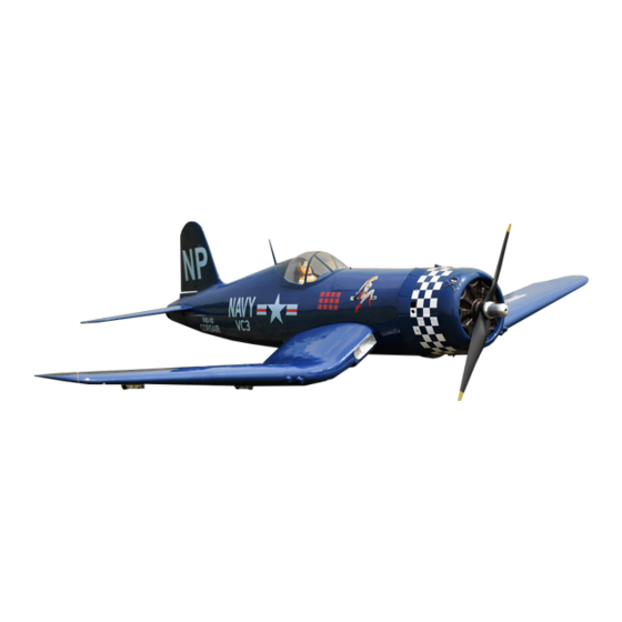
Instruction Manual book
SPECIFICATION
Wingspan :
Length
Weight
Radio
Servo
Engine
1,740 mm
:
1,440 mm
:
4.4 kg
:
06 channels.
:
09 servos + 2 mini servos(wheel door).
:
120
- 4 stroke.
O.S GT 22CC Gas
Item code:BH77
68.50 in.
56.69 in.
9.68 Lbs.
Made in Vietnam.
Advertisement
Table of Contents

Subscribe to Our Youtube Channel
Related Manuals for Black Horse Model Corsair


Summary of Contents for Black Horse Model Corsair
- Page 1 Instruction Manual book Item code:BH77 SPECIFICATION Wingspan : 1,740 mm 68.50 in. Length 1,440 mm 56.69 in. Weight 4.4 kg 9.68 Lbs. Radio 06 channels.
-
Page 2: Parts List
Instruction Manual - Item code: BH77 This instruction manual is designed to help you build a great flying aeroplane. Please read this manual thoroughly before starting assembly of your CORSAIR . Use the parts listing below to identify all parts. WARNING Please be aware that this aeroplane is not a toy and if assembled or used incorrectly it is capable of causing injury to people or property. -
Page 3: Safety Precaution
CORSAIR Instruction Manual - Item code: BH77 Caution: this model is not a toy! If you are a beginner to this type of powered model, please ask an experienced model flyer for help and support. If you attempt to operate the model without knowing what you are doing you could easily injure yourself or somebody else. - Page 4 CORSAIR Instruction Manual - Item code: BH77 REPLACEMENT LARGE PARTS A. Cowling. E.Rudder B. Wing panel(Right&Left). F1. Aluminium tube wing. C. Fuselage. F2.Aluminium tube for Horizontal stabilizer. D.Horizontal stabilizer. G. Decal sheets. REPLACEMENT SMALL PARTS 3x15mm 3x15mm 4x30mm 5x35mm 4x30mm 3x15mm 1.Air retract main gear.
-
Page 5: Installing The Aileron Servos
CORSAIR Instruction Manual - Item code: BH77 Bottom side I. AILERON. 1.INSTALLING THE AILERON SERVOS. 1) Install the rubber grommets and brass eyelets onto the aileron servos. Aileron Flap Top side. Aileron Bottom side 2) Using a modeling knife, remove the cov- ering at possition show below. - Page 6 CORSAIR Instruction Manual - Item code: BH77 Secure 3) Using the thread as a guide and using masking tape, tape the servo lead to the end of the thread: carefully pull the thread out. When you have pulled the servo lead out, re-...
-
Page 7: Installing The Aileron Linkages
CORSAIR Instruction Manual - Item code: BH77 2. Attach the clevis to the outer hole in the control horn. Install a silicone tube on the clevis. 3. Plug the aileron servo into the receiver A+B Epoxy and center the servo. Install the servo arm onto PLUS the servo. -
Page 8: Installing The Flap Servos
CORSAIR Instruction Manual - Item code: BH77 Cut. Flap Flap 6. Insert the 90 degree bend down through the hole in the servo arm. Install one nylon snap keeper over the wire to secure it to the arm. Install the servo arm retaining screw and remove the masking tape from the aileron. - Page 9 CORSAIR Instruction Manual - Item code: BH77 Secure Flap Control horn. 3. INSTALLING THE FLAP LINKAGES. Installing the flap linkages as pictures below. Repeat the procedure for the other wing half. 2. INSTALLING THE FLAP CONTROL HORN. Flap control horn.
- Page 10 CORSAIR Instruction Manual - Item code: BH77 Bottom side. Flap. Aileron. Cut. Repeat the procedure for the other wing half. INSTALLING SERVOS WHEEL DOOR. Flap Open servo Flap. Wire servo. Flap.
- Page 11 CORSAIR Instruction Manual - Item code: BH77 open Secure. Secure.
-
Page 12: Landing Gear
CORSAIR Instruction Manual - Item code: BH77 3x15mm INSTALLING AIR RETRACTABLE LANDING GEAR. 3x15mm 5x35mm 5x35mm... - Page 13 CORSAIR Instruction Manual - Item code: BH77 3x15mm Secure C/A glue 5 x 3 5 m m...
- Page 14 CORSAIR Instruction Manual - Item code: BH77 S e c u r e . Bottom side. Secure Repeat the procedure for the other gear...
-
Page 15: Installing The Engine Mount
CORSAIR Instruction Manual - Item code: BH77 INSTALLING THE ENGINE MOUNT. See pictures below: 4X30mm 4X30mm INSTALLING THE ENGINE. Locate the long piece of wire used for the throttle pushrod. One end of the wire has been pre-bend in to a “Z” bend at the factory . This “Z”... -
Page 16: Installing Fuel Tank
CORSAIR Instruction Manual - Item code: BH77 Right side Pushrod wire. Left side INSTALLING FUEL TANK . INSTALLING THE STOPPER ASSEMBLY 1) The stopper has been pre-assembled at the factory. 2) Using a modeling knife, cut one length of... - Page 17 CORSAIR Instruction Manual - Item code: BH77 Secure silicon tube not included. When the stopper assembly is installed in the tank, the top of the vent tube should 8) Feed three lines through the fuel tank rest just below the top surface of the tank.
-
Page 18: Installing The Throttle Pushrod
CORSAIR Instruction Manual - Item code: BH77 INSTALLING THE THROTTLE PUSHROD. Install one adjustable metal connector through the third hole out from the center of one servo arm, enlarge the hole in the servo arm using a 2mm drill bit to accommodate the Fuel tank servo connector. - Page 19 CORSAIR Instruction Manual - Item code: BH77 2) While keeping the back edge of the cowl flush with the marks, align the front of the cowl with the crankshaft of the engine. The Secure. front of the cowl should be positioned so the crankshaft is in nearly the middle of the cowl opening.
- Page 20 CORSAIR Instruction Manual - Item code: BH77 Top side Secure Right side Left side Secure Right side Secure Left side Front view. Drill a hole 2mm. 3 x 12mm...
-
Page 21: Elevator Installation
CORSAIR Instruction Manual - Item code: BH77 HORIZONTAL STABILIZER INSTALLATION. Secure. See pictures below: Bottom side Aluminum tube 140 mm ELEVATOR INSTALLATION. SERVO INSTALLATION. 1. Install the rubber grommets and brass collets into the elevator servo. Test fit the servo into the servo tray. - Page 22 CORSAIR Instruction Manual - Item code: BH77 Cut the covering away from the slot. E p o x y glue Temporary pin to keep hinge centered. Assemble then apply drops of thin C/A to center of hinge,on both sides. Epoxy glue...
-
Page 23: Elevator Pushrod Installation
CORSAIR Instruction Manual - Item code: BH77 Top side Control horn elevator. Bottom side. ELEVATOR PUSHROD INSTALLATION. Pushrod install as same as method of pushrod wing. See pictures below: M2 lock nut. ELEVATOR CONTROL HORN INSTALLA- TION. Elevator control horn install as same as the way of aileron control horn. -
Page 24: Mounting The Tail Wheel Bracket
CORSAIR Instruction Manual - Item code: BH77 Rudder servo. MOUNTING THE TAIL WHEEL BRACKET. M2 lock nut. 3X15mm. Bottom side. E l e v a t o r pushrod. Open. RUDDER SERVO INSTALLATION. Rudder servo install as same as method of elevator servo. - Page 25 CORSAIR Instruction Manual - Item code: BH77 Secure Top side. Secure Bottom side. 3x15mm...
-
Page 26: Rudder Installation
CORSAIR Instruction Manual - Item code: BH77 Cut. Rudder cable. Bottom side. Bottom side. Elevator Elevator pushrod pushrod RUDDER INSTALLATION. See picture below: Plastic parts of elevator pushrod. - Page 27 CORSAIR Instruction Manual - Item code: BH77 1. Put the rudder into the fuselage as same as picture below. Top side. Cut the covering away from the slot. C/A glue Top side. Temporary pin to keep hinge centered. INSTALLING SERVO USING FOR VALUE...
- Page 28 CORSAIR Instruction Manual - Item code: BH77 Servo valve control Air tank Valve control 3 way conector Valve one way Air tank Air supply Valve one way Right main gear wing INSTALLING AIR TANK Left main gear wing Valve control...
- Page 29 CORSAIR Instruction Manual - Item code: BH77...
-
Page 30: Installing The Switch
CORSAIR Instruction Manual - Item code: BH77 Do not permanently secure the receiver and battery until after balancing the model. 4) Using a 2mm drill bit, drill a hole through the side of the fuselage, near the receiver , for the antenna to exit. - Page 31 CORSAIR Instruction Manual - Item code: BH77 Left side 3. Insert two wing panels as pictures below. Right wing. Secure.
- Page 32 CORSAIR Instruction Manual - Item code: BH77 See picture wing attach to fuselage. Installing the fuselage hatch as same as pic- ture below. Top side. Cut. Left side. Insert and secure. Right side. Epoxy glue. Insert and secure.
- Page 33 CORSAIR Instruction Manual - Item code: BH77 Accurately mark the balance point on the top of the wing on both sides of the fuselage. The balance point is located 95mm back from the leading edge. This is the balance point at which your model should balance for your first flights.
-
Page 34: Control Throws
5) Check the receiver antenna . It should be fully extended and not coiled up inside the fuselage. 6) Properly balance the propeller. We wish you many safe and enjoy- able flights with your CORSAIR.
Need help?
Do you have a question about the Corsair and is the answer not in the manual?
Questions and answers