Table of Contents
Advertisement
Advenger
2800ST, 3400ST
BR 755, BR 855
QUICKSTART SERVICE MANUAL
Advance MODELS: 56601000, 56601001, 56601002, 56601003, 56601004
56601005, 56601006, 56601007, 56601008, 56601009, 56601010, 56601011
56601012, 56601013, 56601019, 56601020
Nilfi sk MODELS: 56601014, 56601015, 56601016
™
9/09 FORM NO. 56043121
Advertisement
Table of Contents
Troubleshooting

Related Manuals for Nilfisk-Advance Advenger 2800ST


Summary of Contents for Nilfisk-Advance Advenger 2800ST
- Page 1 Advenger ™ 2800ST, 3400ST BR 755, BR 855 QUICKSTART SERVICE MANUAL Advance MODELS: 56601000, 56601001, 56601002, 56601003, 56601004 56601005, 56601006, 56601007, 56601008, 56601009, 56601010, 56601011 56601012, 56601013, 56601019, 56601020 Nilfi sk MODELS: 56601014, 56601015, 56601016 9/09 FORM NO. 56043121...
-
Page 2: Table Of Contents
TABLE OF CONTENTS INTRODUCTION ......................................2 QUICK START SERVICE MANUAL PURPOSE ............................2 GENERAL MACHINE DESCRIPTION ................................2 PARTS AND SERVICE ....................................2 NAMEPLATE ........................................ 2 CAUTION AND WARNING SYMBOLS ................................. 3 GENERAL SAFETY INSTRUCTIONS ................................3 RELATED REFERENCE SOURCES................................4 DIAGNOSTIC AND SERVICE TOOLS ................................. -
Page 3: Form No. 56043121 - Advenger / 2800St, 3400St / Br 755, Br 855
TABLE OF CONTENTS SOLUTION SYSTEM ....................................46 SOLUTION & AXP/EDS SYSTEM ERROR CODES AND MEASUREMENTS - ADVENGER / BR 755, 855 AND ST ......47 TROUBLESHOOTING SOLUTION & AXP/EDS SYSTEM ISSUES......................47 SOLUTION SYSTEM DIAGRAM ................................48 SOLUTION SYSTEM CONTROL ................................49 REPLACING THE SOLUTION SOLENOID VALVE ............................ -
Page 4: Introduction
INTRODUCTION - QUICK START SERVICE MANUAL PURPOSE This manual is a technical resource that Nilfi sk-Advance expects to be utilized while an Advenger / BR 755, 855 or ST is being serviced. It contains information deemed necessary to provide basic troubleshooting, maintenance, and repairs within a timeframe of 2-3 hours maximum. If your repair involves multiple visits to repair the same problem or the repair cannot be completed within 3 hours, a call to Nilfi... -
Page 5: Caution And Warning Symbols
CAUTIONS AND WARNINGS SYMBOLS Advance uses the symbols below to signal potentially dangerous conditions. Always read this information carefully and take the necessary steps to protect personnel and property. DANGER! Is used to warn of immediate hazards that will cause severe personal injury or death. WARNING! Is used to call attention to a situation that could cause severe personal injury. -
Page 6: Related Reference Sources
RELATED REFERENCE SOURCES Nilfi sk-Advance provides Operator Manuals, Sales literature, Parts Lists, Technical Service Bulletins, and Instruction Sheets on our website www. advance-us.com for 24/7 availability of information to order parts, operate, troubleshoot, or repair all current production and most pruned machine models. -
Page 7: Technical Specifications
TECHNICAL SPECIFICATIONS GENERAL Machine Voltage 24 VDC Length (W/squeegee): 60 in (152.4 cm) Dimensions (without Squeegee and Width (body): 27.5 in (70 cm) Scrub Deck) Height (Recovery tank): 51.7 in (131.3cm) Scrub Deck Width: Squeegee Width: 30.3 in (77 cm) 28 disc 32.6 in (82.8 cm) Scrub Deck and Squeegee Widths... -
Page 8: Drive System
TECHNICAL SPECIFICATIONS ELECTRICAL SPECIFICATIONS Number of Batteries 4 / Battery Voltage 6V 310 Ah wet Number of Batteries 4 / Battery Voltage 6V 420 Ah wet Batteries Number of Batteries 4 / Battery Voltage 6V 312 Ah AGM Standard Battery Capacity: 305 amp-hours @ 20-hour rate 24-volt Manufacturer: Delta Q Model: 912-2400-N1... -
Page 9: Scrub System
TECHNICAL SPECIFICATIONS SCRUB SYSTEM Scrub Deck Types Disc and Cylindrical Disc: (2) 14 in (35.6 cm) Scrub Path: 28 in (71.1 cm) Scrub Brush/Pad Sizes Disc: (2) 17 in (43.2 cm) Scrub Path: 34 in (86.4 cm) and Types Cylindrical: (2) 27 in (68.6 cm) Scrub Path: 28 in (71.1 cm) Number of Motors 2 Scrub Motors - Disc Right-hand/Single Motor: .64 HP (480 watts) -
Page 10: Transporting The Machine
TRANSPORTING THE MACHINE CAUTION! Before transporting the machine on an open truck or trailer: Remove the Squeegee Assembly (11) and secure. Tie the machine down securely at the Locations (A) shown in FIGURE 2. Tape and strap all access doors and covers as necessary. In temperatures below freezing, remove all water from the machine and fl... -
Page 11: Jacking Points
JACKING POINTS FIGURE 4 Front - When facing the front of the machine and underneath looking up, place the jack to the left of the chain on the frame member (A) as shown in FIGURE 4. FIGURE 5 Rear – Remove Squeegee Assembly (11) to access these locations. Use a bottle jack at these points (B) as shown in FIGURE 5. -
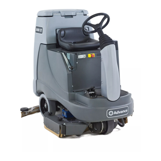
Page 12: Know Your Machine
KNOW YOUR MACHINE MACHINE FRONT RH VIEW Operator’s Seat Solution Tank Drain Hose Drive Pedal, Directional/Speed Drive Wheel Drive Wheel Circuit Breaker (70 Amp) Control Circuit Circuit Breaker (10 Amp) Emergency Stop Scrub Deck Rear Wheel 10 Battery Compartment (under seat) 11 Squeegee Assembly 12 Detergent Cartridge Access Cover (AXP/EDS models only) 13 Detergent Cartridge (AXP/EDS models only) -
Page 13: Machine Rear Lh View
KNOW YOUR MACHINE MACHINE REAR LH VIEW 21 Solution Shutoff Valve 33 Seat Prop-Rod 22 Squeegee Raise/Lower Lever (ST models only) 34 Machine Battery Connector 23 Steering Wheel Tilt Adjust Knob 35 Rear Squeegee Blade Removal Latch 24 Control Panel 36 Hopper (Cylindrical models only) 25 Solution Tank Fill Cover 37 Recovery Hose... -
Page 14: Control Panel - Advenger / Br 755, 855
KNOW YOUR MACHINE CONTROL PANEL (ADVENGER / BR 755, 855 MODELS) Key Switch Solution Increase Switch Scrub Pressure Increase Switch Solution ON/OFF Switch Scrub ON/OFF Switch Solution Flow Indicators (Normal, Heavy & Extreme) Scrub Pressure Indicators (Normal, Heavy and Extreme) Solution Decrease Switch Scrub Pressure Decrease Switch AXP/EDS ON/OFF Switch... -
Page 15: Control Panel - St
KNOW YOUR MACHINE CONTROL PANEL (ST MODELS) Key Switch NOTE 1: Recovery Tank FULL status is indicated by the Solution Flow Solution Increase Switch Indicator LED (C1) turning Off. This status allows machine transport but Solution ON/OFF Switch disables all active systems and disables the control panel switches except Solution Flow Indicators (Normal, Heavy &... -
Page 16: Basic Machine Operation
KNOW YOUR MACHINE As you read this manual, you will occasionally run across a bold number in parentheses – example: (2). A bold number refers to an item shown on the Know Your Machine pages unless otherwise noted (bold letters refer to items on the same page). Refer back to the Know Your Machine pages whenever necessary to pinpoint the location of an item mentioned in the text. -
Page 17: Main Controller Error Codes - Advenger / Br 755, 855 And St
MAIN CONTROLLER ERROR CODES – ADVENGER / BR 755, 855 AND ST Advenger / ST Service BR 755, 855 System LED Blink Fault Description Refer to page: Display Error Affected Code * Code Speed control fault Wheel Drive Scrub deck lift actuator overload Scrub 1, 2 Brush motor overload... -
Page 18: Speed Control Error Flash Codes
SPEED CONTROL ERROR FLASH CODES STATUS LED FAULT CODES (TABLE 1) STATUS LIGHT EXPLANATION POSSIBLE CAUSE CODE DISPLAY over-/under-temperature cutback 1. Temperature >97°C (206°F) or < -25°C (-13°F). 2. Excessive load on vehicle. 3. Operation in extreme environments. 4. Electromagnetic, foot or parking brake not releasing properly. -
Page 19: Error Code System Diagnostics - Advenger / Br 755, 855 And St
ERROR CODE SYSTEM DIAGNOSTICS – ADVENGER / BR 755, 855 AND ST The following table describes the systems that are disabled for each error code to assist you in understanding machine response to error code status. Disable System Flash Indicator Speed control fault Brush deck lift actuator overload Brush motor overload... - Page 20 UNDERSTANDING CONTROL OF SQUEEGEE, SCRUB, AND RECOVERY SYSTEMS VIA MODES Due to the unique One-Touch functions of the new Advenger / BR 755, 855 and ST, multiple systems are engaged via one action defi ned by the Mode that is chosen - Scrub Mode, Vacuum Mode, or Wand Mode.
-
Page 21: Understanding Control Of Squeegee, Scrub, And Recovery Systems Via Modes
UNDERSTANDING CONTROL OF SQUEEGEE, SCRUB, AND RECOVERY SYSTEMS VIA MODES Operator Seat Switch Mode Action Result Position Status Lower Scrub Deck Brush motor circuit enabled Scrub Mode Seated Closed Lower Squeegee Vacuum motor circuit enabled Vacuum motor circuit On Brush motor circuit On Press Foot Pedal Solution Solenoid On Forward... -
Page 22: Squeegee System
SQUEEGEE SYSTEM Refer to the section “Understanding Control of Squeegee, Scrub, and Recovery Systems via Modes” for explanation of control due to functionality of multiple systems in tandem. Advenger / BR 755, 855 20 - FORM NO. 56043121 - Advenger / 2800ST, 3400ST / BR 755, BR 855... -
Page 23: Squeegee Lift Actuator Circuit Error Codes And Measurements - Advenger / Br 755, 855
SQUEEGEE LIFT ACTUATOR CIRCUIT ERROR CODES AND MEASUREMENTS - ADVENGER / BR 755, 855 Advenger / ST Service Fault Description Troubleshooting Action BR 755, 855 Display Blink Code Error Code 1. Check for binding or frozen squeegee lift linkage and excessive weight on squeegee. -
Page 24: Squeegee Adjustments
SQUEEGEE ADJUSTMENTS Correct squeegee alignment is critical to water pickup performance and life of squeegee blades. If the squeegee is not angled correctly or hops, use the following settings as nominal and adjust as necessary to achieve the required performance. Tilt –... -
Page 25: Squeegee Lift Actuator Replacement - Advenger / Br 755, 855
SQUEEGEE LIFT ACTUATOR REPLACEMENT - ADVENGER / BR 755, 855 CAUTION! The Recovery Tank is heavy and care should be taken in removing it. Two people recommended, or battery roll-out unit. Lower the squeegee tool to the fl oor and then disconnect the battery pack at the red Anderson connector in the battery compartment. Drain the recovery tank using the Recovery Tank Drain Hose (31). -
Page 26: Squeegee Lift Actuator Drive Nut Adjustment - Advenger / Br 755, 855
SQUEEGEE LIFT ACTUATOR DRIVE NUT ADJUSTMENT - ADVENGER / BR 755, 855 FIGURE 10 WARNING! Open the battery compartment and disengage the red Anderson battery connectors. Connect the Scrub Deck Lift Actuator (completely assembled) to the Actuator Power Cord Adapter 56407502 (Figure 10) (see “Diagnostic and Service Tools”). -
Page 27: Squeegee Lift Cable Replacement - Advenger / Br 755, 855
SQUEEGEE LIFT CABLE REPLACEMENT - ADVENGER / BR 755, 855 Follow steps 1-6 of “Squeegee Lift Actuator Replacement - Advenger / BR 755, 855” to disengage front end of lift cable under machine. NOTE: the motor does not need to be disconnected for this procedure. See Figure 12. -
Page 28: Squeegee Lift Cable Replacement - St
SQUEEGEE LIFT CABLE REPLACEMENT - ST CAUTION! The Recovery Tank is heavy and care should be taken in removing it. Two people recommended, or battery roll-out unit. REAR: Lower the Squeegee Tool to the fl oor and then disconnect the battery pack at the red Anderson connector in the battery compartment. Drain the recovery tank using the Recovery Tank Drain Hose (31). -
Page 29: Squeegee Lift Cable Adjustment - St
SQUEEGEE LIFT CABLE ADJUSTMENT - ST REAR – Figure 14 Factory setting is 0.25” Follow steps 1 – 6 of Squeegee Lift Actuator Replacement - Advenger / BR 755, 855 If the cable is too long and the squeegee doesn’t lift off the ground, move the nut closest to the squeegee away from the machine, decreasing the distance from the nut to the reference end (Figure 14). -
Page 30: Steering Column Assembly Shroud Removal
STEERING COLUMN ASSEMBLY SHROUD REMOVAL See Figure 16. Remove the 4 screws fastening the Lower Column Shroud (A) to the Lower Column Weldment. (ST) Using a 7/16” socket, remove Squeegee Lift Knob and Linkage Arm (B). Using a fl at bladed screwdriver, pry off the steering wheel plastic center cap. Using a ¾”... -
Page 31: Scrub System
SCRUB SYSTEM Advenger / BR 755, 855 - pressing the Scrub On button with the seat switch closed causes the scrub deck and squeegee to drop. The control board provides 24V to the deck lift actuator M4; this signal is DVM measureable for 3 seconds and then becomes a pulsed signal while the deck is down. - Page 32 SCRUB SYSTEM ST - with the seat switch closed, lowering the squeegee and brush deck and pressing the drive pedal forward causes the brush and vacuum contactors to energize. The 24V brush and vacuum motors turn on; the pulsed solution solenoid turns on. Combined brush motor current is monitored via the YEL/VIO sense wire.
-
Page 33: Brush Motor Control And Load Circuit Error Codes And Measurements
BRUSH MOTOR CONTROL AND LOAD CIRCUIT ERROR CODES AND MEASUREMENTS Advenger / ST Service BR 755, 855 Fault Description Troubleshooting Action Display Blink Code Error Code 1. Check for binding in rotation of brushes or improper brush lift actuator operation. 2. -
Page 34: Scrub Deck Lift Actuator Error Codes And Measurements - Advenger / Br 755, 855
SCRUB DECK LIFT ACTUATOR ERROR CODES AND MEASUREMENTS - ADVENGER / BR 755, Advenger / BR 755, 855 Service LED Fault Description Troubleshooting Action Display Blink Code Error Code 1. Check for improper actuator adjustment – refer to Actuator Drive Nut Adjustment section. -
Page 35: Scrub Deck Lift Actuator Replacement - Advenger / Br 755, 855
SCRUB DECK LIFT ACTUATOR REPLACEMENT - ADVENGER / BR 755, 855 Lower the scrub deck per the instructions found in “Service Test Mode.” Quickly disconnect the batteries at the red Anderson battery connector inside the battery compartment. This is done not only for safety but to keep the deck from rising. -
Page 36: Scrub Deck Lift Actuator Drive Nut Adjustment - Advenger / Br 755, 855
SCRUB DECK LIFT ACTUATOR DRIVE NUT ADJUSTMENT - ADVENGER / BR 755, 855 FIGURE 18 WARNING! Open the battery compartment and disengage the red Anderson battery connectors. Connect the Scrub Deck Lift Actuator (completely assembled) to the Actuator Power Cord Adapter 56407502 (see “Diagnostic and Service Tools”). -
Page 37: Scrub Deck Removal-Disc
SCRUB DECK REMOVAL - DISC WARNING! DISCONNECT BATTERIES BEFORE SERVICING. Scrub Deck Removal / Re-installation Remove both deck side skirt assemblies. Lower the scrub deck with brushes (pads) installed. STD / AXP / EDS SERVICE NOTE: Don’t turn the key switch off until after disconnecting the battery. -
Page 38: Scrub Brush Motor Removal-Disc
SCRUB BRUSH MOTOR REMOVAL - DISC (also needed for Carbon Brush check) See SCRUB DECK REMOVAL-DISK to remove the scrub deck assembly. See Figure 21. After removing the deck turn it over so the Brush Plates are on top. Remove the hex socket screw (A) from the Motor Gimbal located at the Brush Plate center. Remove the Brush Plate Assembly (B). - Page 39 SCRUB BRUSH MOTOR REMOVAL - DISC FIGURE 22 See Figure 22. Mark the bolt locations (A) before removing them because one deck is used for all deck sizes and there are multiple confi gurations. See Figure 23. Extract the solution hose (B) from the motor bracket (C).
-
Page 40: Scrub Deck Removal-Cylindrical
SCRUB DECK REMOVAL - CYLINDRICAL WARNING! DISCONNECT BATTERIES BEFORE SERVICING. Scrub Deck Removal / Re-installation Remove both deck side skirt assemblies and the debris tray. Lower the scrub deck with brushes installed. STD / AXP / EDS SERVICE NOTE: Don’t turn the key switch off until after disconnecting the battery pack. -
Page 41: Scrub Brush Motor Removal-Cylindrical
SCRUB BRUSH MOTOR REMOVAL - CYLINDRICAL See SCRUB DECK REMOVAL-CYLINDRICAL to remove the scrub deck assembly. See Figure 25. Remove the Belt Cover (A) on each side. With an operator in the driver’s seat with the key switch On and the increase scrub function selected press the drive pedal to start the scrub brushes and observe which brush motor needs to be replaced. -
Page 42: Recovery System
RECOVERY SYSTEM The recovery system is controlled via the control board output to contactor K1 coil, turning on one or both (if equipped) vac motors M5 (M6), with control board feedback provided via the BRN/RED vac motor current-monitoring sense wire. Refer to the section “Understanding Control of Squeegee, Scrub, and Recovery Systems via Modes”... - Page 43 FORM NO. 56043121 - Advenger / 2800ST, 3400ST / BR 755, BR 855 - 41...
-
Page 44: Recovery System Error Codes And Measurements
RECOVERY SYSTEM ERROR CODES AND MEASUREMENTS Advenger / BR 755, Service LED Fault Description Troubleshooting Action 855 Display Blink Code Error Code 1. Check for debris in vac motor 2. Check for worn carbon brushes 3. Check for defective/corroded motor bearings 4. -
Page 45: Troubleshooting Recovery System Issues
TROUBLESHOOTING RECOVERY SYSTEM ISSUES Problem Possible Cause Advenger / BR 755, 855 and ST 1. Misadjusted squeegee tool - refer to “Squeegee Alignments” section 2. Worn or damaged blades - refer to Operating Manual for instructions 3. Leak in vacuum system - check for bad gasket, leaky hose, damaged tank, leaky drain Poor water pickup from squeegee tool valve. -
Page 46: Replacing A Vacuum Motor
REPLACING A VACUUM MOTOR WARNING! DISCONNECT BATTERIES BEFORE SERVICING. RECOVERY TANK REMOVAL See Figure 26. Drain the Recovery Tank (A) using the Drain Hose(B). Disconnect the Recovery Hose (C) from the squeegee. Disconnect the vacuum motor wiring from the main harness. NOTE: Also disconnect optional Beacon wiring if installed. Remove the Recovery Tank (A) from the machine. - Page 47 REPLACING A VACUUM MOTOR VACUUM MOTOR ASSEMBLY REMOVAL See Figure 27. Lay the Recovery Tank (A) on it's back. Remove the (6) Screws (B) and remove the Vacuum Motor Cover (C) from the tank. Remove Plate and Gaskets (D) and Vacuum Motor (E). NOTE: The wires should be protruding up through the hole and not from around the edge of the plate.
-
Page 48: Solution System
SOLUTION SYSTEM The Solution System is controlled via a pulsed 24V signal from the control board at J3-11 to the Solution Solenoid valve. On Advenger / BR 755, 855 machines, the solution fl ow rate is also controlled via feedback provided by a pressure sensor on the control board. For more details, refer to the “Solution System Control”... -
Page 49: Solution & Axp/Eds System Error Codes And Measurements - Advenger / Br 755, 855 And St
SOLUTION & AXP/EDS SYSTEM ERROR CODES AND MEASUREMENTS - ADVENGER / BR 755, 855 AND ST Advenger / Fault Description Troubleshooting Action ST Service BR 755, 855 Display Blink Code Error Code 1. Check for a wiring problem. 2. Check coil resistance (see below). 1, 4 Solution solenoid overload 3. -
Page 50: Solution System Diagram
SOLUTION SYSTEM DIAGRAM FIGURE 28 48 - FORM NO. 56043121 - Advenger / 2800ST, 3400ST / BR 755, BR 855... -
Page 51: Solution System Control
SOLUTION SYSTEM CONTROL Advenger / BR 755, 855 The control board output of pulsed voltage signals driving the Solution System is controlled by the following three parameters: The deck size and type (factory set but selectable via Hidden Menu). The Solution Flow Rate chosen by the operator through the user interface. The Liquid Level Sensor. -
Page 52: Replacing The Solution Solenoid Valve
REPLACING THE SOLUTION SOLENOID VALVE Advenger / BR 755, 855 - follow instructions found in “Service Test Mode” to lower the scrub deck. ST - manually lower the scrub deck. WARNING! Quickly disconnect the batteries at the red Anderson connectors in the battery compartment (done for safety and to keep the deck from rising back up). -
Page 53: Wheel Drive System
WHEEL DRIVE SYSTEM The drive wheel assembly is directly connected to the Curtis 1228 speed control, which not only provides an output signal of 24V to the drive wheel for forward and reverse movement, but also monitors current and temperature, and controls the electromagnetic brake. It is the same for both the Advenger / BR 755, 855 and ST models. -
Page 54: Wheel Drive Circuit Error Codes And Measurements
WHEEL DRIVE CIRCUIT ERROR CODES AND MEASUREMENTS Advenger / ST Service Fault Description Troubleshooting Action BR 755, 855 Display Blink Code Error Code Speed control fault 1. Verify connector at Drive Pedal is connected (will disable all systems unless fault 2. -
Page 55: Replacing The Drive Wheel Assembly
REPLACING THE DRIVE WHEEL ASSEMBLY WARNING! Park the machine on a dry fl at surface, turn the main key switch (J) to the Off position and disconnect the battery pack at the red Anderson connectors inside the battery compartment. Block the rear wheels. Jack up the front of the machine as shown in “Jacking Points”... -
Page 56: Replacing The Drive Tire
REPLACING THE DRIVE WHEEL ASSEMBLY (CONTINUED) 11 Reassemble the drive wheel in reverse order, attaching the motor wires as shown. CAUTION! Use a Torque Wrench set at 20 ft-lb to retighten the 1 1/2” hex nut at the top of the steering spindle. NOTE Orient the wires in such a way as to minimize bending at the crimps for optimum motor performance. -
Page 57: Inspecting/Replacing The Drive Wheel Assembly Carbon Brushes
INSPECTING/REPLACING THE DRIVE WHEEL ASSEMBLY CARBON BRUSHES FIGURE 37 IMPORTANT! To remove/replace/inspect the Carbon Brushes, observe the following: The motor must come off of the machine. The motor assembly must be kept vertical while being disassembled to prevent loss of gear oil. WARNING! Park the machine on a dry fl... -
Page 58: Replacing The Rear Wheels
REPLACING THE REAR WHEELS WARNING! Park the machine on a dry fl at surface, turn the main key switch Off and disconnect the battery pack at the red Anderson connectors in the battery compartment. Block the front Drive Wheel (4). Jack the Rear Wheel (9) to be replaced per the instructions at the front of this manual in “Jacking Points”... -
Page 59: Electrical System
ELECTRICAL SYSTEM FIGURE 39 ACCESS TO PANEL: CHEMICAL PUMP, CHARGER INTERLOCK, FUSES, CONTACTORS, SPEED CONTROL WARNING! Open the battery compartment and disengage the red Anderson battery connectors. Remove the 3 (AXP/EDS - 4) screws fastening the electrical panel to the front of the machine. See Figure 39. -
Page 60: Control Board J1, J2, And J3 Pin Outs And Test Points
CONTROL BOARD J1, J2, AND J3 PIN OUTS AND TEST POINTS CAUTION! Always take measurements at the end connectors for troubleshooting purposes. If readings taken there do not indicate the problem, check the control board as a last resort as damage to the board may occur (see Caution statements in “Replacing Operator Control Panel” section). Use a DVM and extended insulated probe tips (shown) to take the following measurements. - Page 61 Backprobe J2 - Speed Control outputs, ST deck and squeegee lever position, and sense wires, J2 connected at control board: Referenced to Measure Measure Referenced to ST squeegee lever switch S6 BLK/YEL Closed sq down 0V Open sq up 5V ST deck lever switch S5 ORN/RED Closed deck up 0V...
-
Page 62: Curtis Speed Control Installation Checkout Procedure
CURTIS SPEED CONTROL INSTALLATION CHECKOUT PROCEDURE After installing a controller and before operating the vehicle, carefully complete the following checkout procedure. If you fi nd a problem during checkout, refer to the Curtis programmer manual for more information. The installation checkout can be conducted with or without the handheld programmer. The checkout procedure is easier with a programmer otherwise observe the Status LED for codes (located on operator panel wand indicator light). -
Page 63: Replacing The Operator Control Panel
REPLACING THE OPERATOR CONTROL PANEL WARNING! DISCONNECT BATTERIES BEFORE SERVICING. CAUTION! To prevent damage to the new control panel assembly due to static electricity (ESD), wear a properly grounded static control wrist strap before removing the new assembly from its protective static shielding bag and throughout the entirety of the installation process until the four screws attaching the assembly to the machine have been re-fastened. - Page 64 REPLACING THE OPERATOR CONTROL PANEL CONTROL PANEL DISASSEMBLY, ASSEMBLY AND INSTALLATION See Figure 42. Remove the Key Switch (A) from the panel assembly. Remove the (5) Screws (B), the Circuit Board (C) and the Tab (D) from the panel assembly. NOTE: Save Items (A-D) and discard the panel assembly.
-
Page 65: Programming Functions
PROGRAMMING FUNCTIONS SERVICE TEST MODE - ADVENGER / BR 755, 855 The purpose of Service Test Mode is to by-pass the lock-out function of the normal control system of components that are in an error state and allow those components to be manually turned on and off for troubleshooting purposes. (Components in an overload error state will still be locked out for safety reasons.) Advenger / BR 755, 855 - Service Test Mode is accessed via the Hidden Menus. - Page 66 PROGRAMMING FUNCTIONS SERVICE TEST MODE - ST The purpose of Service Test Mode is to by-pass the lock-out function of the normal control system of components that are in an error state and allow those components to be manually turned on and off for troubleshooting purposes. (Components in an overload error state will still be locked out for safety reasons.) ST - To enter Service Test Mode, turn key switch Off, then press and hold the three buttons shown below simultaneously.
-
Page 67: Changing Control Board Program Settings
CHANGING CONTROL BOARD PROGRAM SETTINGS Although the Advenger / BR 755, 855 and ST are delivered with a standard factory preset confi guration, there will be times, such as when a control board is replaced, when battery type is changed, or a different size scrub deck is installed, when some parameters in the control system software will need to be changed. -
Page 68: Changing Program Settings - Advenger / Br 755, 855
CHANGING PROGRAM SETTINGS - ADVENGER / BR 755, 855 To enter this Hidden Menu, turn the key switch Off, then press and hold the Scrub and Vacuum switches together. Turn key switch back On and hold the switches for 2 seconds until the Solution and Scrub indicators both turn on. Release both switches - the display will now read “Programming Options.”... -
Page 69: Changing Program Settings - St
CHANGING PROGRAM SETTINGS - ST To enter this Hidden Menu, turn key switch Off, then press and hold the buttons shown in the table below simultaneously. Turn key switch back On and hold for 2 seconds until the indicated LEDs for the desired function turn On, then release the switches. Use the Solution + or - switches to change the setting. -
Page 70: Maintenance Schedules
MAINTENANCE SCHEDULES OPERATOR PREVENTIVE MAINTENANCE – MACHINE IN USE MAINTENANCE ITEM Daily Weekly Monthly Charge Batteries ● Check/Clean Tanks & Hoses ● Check/Clean/Adjust Squeegee ● Check/Clean/Rotate Brushes/Pads ● Empty/Clean Strainer Basket in Recovery Tank ● Check/Clean Vacuum Shut-Off Float ● Check/Clean vacuum motor foam fi... -
Page 71: Operator Preventive Maintenance - Machine In Storage
MAINTENANCE SCHEDULES OPERATOR PREVENTIVE MAINTENANCE – MACHINE IN STORAGE MAINTENANCE ITEM Daily Weekly Monthly Yearly Check Each Battery Cell’s Water Level (wet) ● Charge Batteries – full charge cycle 12-15 hrs ● SERVICE TECHNICIAN SUGGESTED MAINTENANCE MAINTENANCE ITEM Quarterly Yearly Clean battery tops and posts with baking soda solution ●... -
Page 72: Pm Checklist
Advance Advenger 2805, 2905, 3405 Advance 2800ST, 3400ST Nilfi sk BR 755, 855 Disc and Cylindrical PM Checklist Defect Codes Customer needs adjustment binding Address dirty or contaminated damaged, bent or torn City leaks missing Model Serial Hours worn out OPERATIONAL INSPECTION ITEMS OK or Defect Codes... - Page 73 VISUAL INSPECTION ITEMS Comments OK or D e f e c t Does Not Codes Work (circle) Scrub Brushes (check for wear and rotate) A B D W Scrub Brush Motor Carbon Brushes Wear Limit 3/8” B L W Scrub Brush Motor Gimbals In Brush Plates Auto Tension Belt –...
-
Page 75: Expanded Electrical System
ELECTRICAL SYSTEM COMPONENT LOCATION (Advenger / BR 755, 855) Item Description Control PCB Assy Controller, Speed Fuse 150 Amp Circuit Breaker, 70 Amp Circuit Breaker, 10 Amp Beacon, Warning (optional) Horn/Backup Alarm Contactor, Vacuum Motor Contactor, Brush Motor Solenoid Valve Motor / Drive Wheel Pump, Chemical (AXP/EDS only) Squeegee Lift Actuator... -
Page 76: Wiring Diagram - Advenger / Br 755, 855
ELECTRICAL SYSTEM WIRING DIAGRAM / SCHEMATIC (Advenger / BR 755, 855) Item Ref. No. Qty Description 56601565 Control PCB Assy 56601061 Controller, Speed Battery 56412089 Fuse, 150 Amp 56454429 Circuit Breaker, 70 Amp 56507644 Circuit Breaker, 10 Amp 56307166 Beacon, Warning (optional) 56412177 Horn/Backup Alarm 56601183... -
Page 77: Electrical Schematic - Advenger / Br 755, 855
ELECTRICAL SYSTEM FORM NO. 56043121 - Advenger / 2800ST, 3400ST / BR 755, BR 855- 77... -
Page 78: Component Location - St
ELECTRICAL SYSTEM COMPONENT LOCATION (2800ST, 3400ST) Item Description Control PCB Assy Controller, Speed Fuse 150 Amp Circuit Breaker, 70 Amp Circuit Breaker, 10 Amp Beacon, Warning (optional) Horn/Backup Alarm Contactor, Vacuum Motor Contactor, Brush Motor Solenoid Valve Motor / Drive Wheel Motor, Vacuum Motor, Vacuum (Optional) Motor, Brush... -
Page 79: Wiring Diagram - St
ELECTRICAL SYSTEM WIRING DIAGRAM / SCHEMATIC (2800ST, 3400ST) Item Ref. No. Qty Description 56601566 Control PCB Assy 56601061 Speed Control Battery 56412089 Fuse, 150 Amp 56454429 Circuit Breaker, 70 Amp 56507644 Circuit Breaker, 10 Amp 56307166 Beacon, Warning (optional) 56412177 Horn/Backup Alarm 56601183 Contactor 24v, 100 Amp... -
Page 80: Electrical Schematic - St
ELECTRICAL SYSTEM 80 - FORM NO. 56043121 - Advenger / 2800ST, 3400ST / BR 755, BR 855... - Page 81 www.nilfi sk-advance.com © 2008...
Need help?
Do you have a question about the Advenger 2800ST and is the answer not in the manual?
Questions and answers