Table of Contents
Advertisement
Advertisement
Table of Contents
Troubleshooting

Related Manuals for Nilfisk-Advance ConvertaMAX 28


Summary of Contents for Nilfisk-Advance ConvertaMAX 28
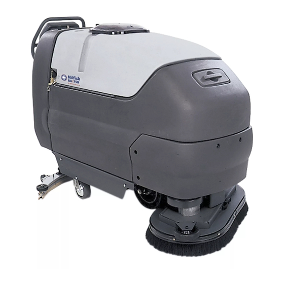
- Page 1 ™ ConvertaMAX 28/34 ™ I-MAX 28HD/34HD BA 750/850 SERVICE MANUAL Advance MODELS (Active 56396015, 56396019, 56396016, 56396020) (Obsolete 56396000, 56397200, 56396001, 56397201) Nilfisk MODELS (Active 56396017, 56396018) (Obsolete 56396002, 56396003) 5/00 revised 12/02 Form Number 56043057...
-
Page 2: Table Of Contents
TABLE OF CONTENTS GENERAL INFORMATION ..............................2 SAFETY INSTRUCTIONS ..............................3 SPECIFICATIONS & MAINTENANCE ..........................4-6 PM CHECKLIST ................................... 7 KNOW YOUR MACHINE ............................... 9-13 SOLUTION SYSTEM ..............................14-19 FUNCTIONAL OVERVIEW .............................. 14 TROUBLESHOOTING GUIDE & SYSTEM MAINTENANCE ................... 15 SOLUTION SOLENOID VALVE REMOVAL (BEFORE SN BREAK) ................ - Page 3 TABLE OF CONTENTS ELECTRICAL SYSTEM ..............................44-67 BATTERIES / CHARGERS .............................. 44 INSTALL THE BATTERIES .............................. 44 DESCRIPTION OF LOW VOLTAGE CUTOUT FEATURE ....................44 DESCRIPTION OF THE BATTERY CONDITION INDICATORS ..................45 BATTERY CHARGING, MAINTENANCE AND TESTING ....................45 ACTUATOR DRIVE NUT ADJUSTMENT ........................
-
Page 4: General Information
Repairs, when required, should be performed by your Authorized Nilfisk-Advance Service Center, who employs factory trained service personnel, and maintains an inventory of Nilfisk-Advance original replacement parts and accessories. Call the NILFISK-ADVANCE DEALER named below for repair parts or service. Please specify the Model and Serial Number when discussing your machine. -
Page 5: Safety Instructions
• This machine is not suitable for picking up hazardous dust. • Use care when using scarifier discs and grinding stones. Nilfisk-Advance will not be held responsible for any damage to floor surfaces caused by scarifiers or grinding stones. •... -
Page 6: Specifications & Maintenance
SPECIFICATIONS Model designation: (A)=ConvertaMAX 28 & BA 750, (B)=I-MAX 28HD, (C)=BA 850, (D)=ConvertaMAX 34, (E)=I-MAX 34HD General Specifications Machine Length (English) 64 in. 65 in. 67.5 in. 67.5 in. 67.5 in. Metric 163cm 165cm 172 cm 172 cm 172 cm Machine Width with Squeegee (English) 36.25 in. - Page 7 SPECIFICATIONS Squeegee Width Width TOP VIEW Length Height SIDE VIEW ™ ™...
- Page 8 MAINTENANCE MAINTENANCE SCHEDULE Maintenance intervals given are for average operating conditions. Machines used in severe operational environments may require service more often. MAINTENANCE ITEM Daily Weekly Monthly Yearly Charge the Batteries Drain / Clean and Check Tanks & Hoses Check / Clean / Rotate the Brushes/Pads Check / Clean / Adjust the Squeegee Check / Clean Vacuum Shut-Off Float Check Each Battery Cell’s Water Level...
-
Page 9: Pm Checklist
Advance ConvertaMAX 28/34, I-MAX 28HD/34HD Models 56396000, 56397200, 56396001, 56397201, 56396015, 56396019, 56396016, 56396020 Nilfisk BA 750/850 Models 56396002, 56396003, 56396017, 56396018 PM Checklist Defect Codes Customer needs adjustment binding Address dirty or contaminated damaged, bent or torn City leaks... - Page 10 BLANK ™ ™ revised 12/02...
-
Page 11: Know Your Machine
KNOW YOUR MACHINE Solution Tank Fill Battery Charger Connector Recovery Tank & Cover Solution Flow Control Knob Drive Paddle Speed Limit Control Knob Solution Drain Hose / Level Indicator Wheel Drive Circuit Breaker (40 Amp) Recovery Drain Hose Control Circuit Circuit Breaker (10 Amp) Squeegee Adjustment Bolt Brush Deck Squeegee Blade Latch... - Page 12 KNOW YOUR MACHINE CONTROL PANEL Battery Condition Indicator Hourmeter/Status Display Main Power Indicator Master On/Off Key Switch Solution System Indicator Solution System Fault Indicator Solution Button Vacuum System Fault Indicator Vacuum Button Vacuum System Indicator Heavy Scrub Button Heavy Scrub Mode Indicator Normal Scrub Button Normal Scrub Mode Indicator Scrub Off Button...
- Page 13 KNOW YOUR MACHINE FUNCTIONAL DESCRIPTION OF CONTROLS: Solution Tank Fill (1) – Open to fill the solution tank, use non-foaming chemicals only. Capacity is 24 or 30 gallons (90 or 113 Liters) depending on model. Recovery Tank & Cover (2) – Rear of tank is entry for waste water into tank. Capacity is 24 or 30 gallons (90 or 113 Liters) depending on model. Cover also houses float ball, which shuts off vacuum port to vac motor when tank is full.
- Page 14 KNOW YOUR MACHINE Heavy Scrub Button (27) - Pressing the heavy scrub button will enable the scrub system and set the scrub pressure to the last selected value for the heavy scrub mode. The status display will momentarily display the scrub pressure setting. This is indicated by “PA” followed by a number. Subsequent presses of the heavy scrub button will step the pad pressure setting through the allowable range up to the maximum value programmed for the heavy scrub mode.
- Page 15 KNOW YOUR MACHINE DESCRIPTION OF INDICATORS ON THE CONTROL PANEL: (CONTINUED) Solution System Indicator (21): • This indicator will be YELLOW if the solution system is in the AUTO mode and the Drive Paddle (3) is in the neutral position. This indicates that the solution system is enabled but the solution flow is currently off.
-
Page 16: Solution System
SOLUTION SYSTEM FUNCTIONAL OVERVIEW ™ ™ ™ The ConvertaMAX 28, I-MAX 28HD and BA 750/850 models have a solution tank fill capacity of 24-gallons (90 liters). The ConvertaMAX and I-MAX ™ 34HD models tank capacities are 30-gallons (114 liters). All models use two tank fill openings one located in the front and another in the rear, which offers ease of filling. -
Page 17: Troubleshooting Guide & System Maintenance
SOLUTION SYSTEM TROUBLESHOOTING GUIDE Problem Possible Cause Inadequate or no solution flow No solution in the tank Main solution flow control valve knob is in the off position Clogged solution filter, valves and hoses Defective solution solenoid valve (L1) Solution system fault in the main controller A2* *Reference the Main Control Board Troubleshooting Guide in the Electrical System of this manual for further information. -
Page 18: Solution Valve Disassembly And Cleaning (Before Sn Break)
SOLUTION SYSTEM SOLENOID VALVE DISASSEMBLY AND CLEANING (BEFORE SN BREAK)* Remove the solenoid valve. See the Solenoid Valve Removal section for instructions. See Figure 3. Remove the (2) (G) Screws and nuts and disassemble the valve (be careful not to lose any internal parts). Thoroughly wash dirt from block (H) and diaphragm (I). - Page 19 SOLUTION SYSTEM ™ ™ FIGURE 4A ConvertaMAX 28, I-MAX 28HD, BA 750 & BA 850 FRONT FIGURE 4B ConvertaMAX ™ 34 & I-MAX ™ 34HD FRONT revised 12/02 ™ ™...
-
Page 20: Solution Solenoid Valve Removal (After Sn Break)
SOLUTION SYSTEM SOLENOID VALVE REMOVAL (AFTER SN BREAK)** Drain the solution tank or put the Flow Control Valve Knob (A) (shown in Figure 1) in the full off position to prevent solution loss. Remove the lower left side chassis panel (held in place by 3 screws) and the left side scrub brush skirt assembly from the machine. See Figure 5. -
Page 21: Solution Flow Control Valve Removal (After Sn Break)
SOLUTION SYSTEM SOLUTION FLOW CONTROL VALVE REMOVAL (AFTER SN BREAK)** Drain the solution tank using the drain hose. See Figure 6A or 6B. Loosen the (2) Hose Clamps (DD) and (EE) and pry off inlet solution Hose (FF) from the flow control valve. Remove the Philips head Screw (GG) (using a short handled screwdriver) that secures the operator solution adjustment rod (HH) to the ball valve arm and separate. -
Page 22: Scrub Brush System
SCRUB BRUSH SYSTEM GENERAL BRUSH SYSTEM FUNCTIONAL OVERVIEW Two permanent magnet DC motor/gear units drive all machine models’ scrub brushes. The C-Max 28, BA750&850 models use 3/4HP 24V motors and the I-Max 28HD uses 1HP 24V motors. The larger C-Max 34 model uses 3/4HP 36V motors and the heavy duty I-Max uses 1 HP 36V motors. The scrub deck on all models is raised and lowered automatically using a vertically mounted lift motor actuator assembly. - Page 23 SCRUB BRUSH SYSTEM FIGURE 1 revised 12/02 ™ ™...
-
Page 24: Scrub Brush System Troubleshooting
SCRUB BRUSH SYSTEM SCRUB BRUSH SYSTEM TROUBLESHOOTING The scrub system’s major electrical components are monitored by the main controller to detect any system function failures (error codes). The system components covered are the brush motors, brush solenoid and brush lift actuator motor. Detected error codes from the main controller are displayed on the hour meter LED display as they occur. -
Page 25: 28/34 Brush Deck Removal
With scrub brushes installed and the brush deck in the up (storage) position disconnect the actuator motor wiring harness pig tail connector. Next connect the Nilfisk-Advance actuator power cord adapter (PN 56407502) to the machine’s battery pack and lift actuator motor pig tail connector. - Page 26 SCRUB BRUSH SYSTEM FIGURE 3 Jumper Plate These Two Terminals These Two Terminals are Connected with a are Connected with a Jumper Plate (inset) Jumper Plate (inset) Left* Right* Brush FRONT Brush Motor Motor ™ ™ ™ Motor wiring for: ConvertaMAX 28, BA 750, BA 850, ConvertaMAX 34 and I-MAX 34HD...
-
Page 27: Recovery System
RECOVERY SYSTEM FUNCTIONAL OVERVIEW Vacuum / Recovery System General Dirt and water are lifted off the floor into the recovery tank by airflow, created by a 3-Stage 24V or 36V vacuum motor. The wastewater and air enter the vacuum system at the squeegee tool, through small openings (notches) located in the front squeegee blade. The small openings are the entrance points for the water and air, and help speed up the airflow producing the suction to lift the wastewater off of the floor. -
Page 28: Vacuum/Recovery System Maintenance Checklist
RECOVERY SYSTEM VACUUM / RECOVERY SYSTEM SERVICE MAINTENANCE CHECKLIST Whenever there is a vacuum problem, it’s best to check over the entire system. Use the checklist below as a guide, to thoroughly check the vacuum system. Clean built-up dirt from the inside of the squeegee tool. Replace the squeegee blades if they are nicked or torn. - Page 29 RECOVERY SYSTEM FIGURE 2 FRONT revised 12/02 ™ ™...
-
Page 30: Squeegee System
SQUEEGEE SYSTEM SQUEEGEE SYSTEM LIFT MOTOR OVERVIEW All machine models’ squeegee pickup tools are raised and lowered by either a 24V or 36V actuator motor assembly mounted in the rear control handle housing. The control board assembly A2 regulates the machine’s squeegee tool system input and output operating functions. Pressing the vacuum button located on the control panel activates the vacuum/squeegee circuit. -
Page 31: Reverse Switch Installation And Adjustment
SQUEEGEE SYSTEM REVERSE SWITCH INSTALLATION AND ADJUSTMENT Loosely install the S3 reverse switch to the drive paddle mount bracket then connect the wires as shown (see Figure 3). Next position the Cam Controller (A) to where the switch arm just makes contact at the base of the cam controller ramp angle as shown. Note: The correct switch installation is where the switch arm is not compressed and is in its normally closed position. -
Page 32: Squeegee Lift Actuator Motor Removal
SQUEEGEE SYSTEM SQUEEGEE LIFT ACTUATOR MOTOR REMOVAL See Figure 5. Remove the squeegee pickup tool from the squeegee mount. Remove the drain hose from its mount and lay it to the side. Next remove the rear panel from the control handle housing secured by (6) screws, this allows access to the squeegee actuator motor. - Page 33 SQUEEGEE SYSTEM FIGURE 5 FRONT *Note: Figure 5 shows the squeegee tool for the ConvertaMAX ™ 28, I-MAX ™ 28HD, and BA 750, the squeegee tool for the ConvertaMAX ™ ™ I-MAX 34HD, and BA 850 is similar in adjustment and blade replacement. revised 12/02 ™...
-
Page 34: Wheel Drive System
WHEEL DRIVE SYSTEM GENERAL FUNCTIONAL OVERVIEW See Figures 1 and 3. A 3/4 horsepower permanent magnet (24V or 36V) motor/gear unit (M6) is used for the wheel drive on all machines. The motor/gear unit output is delivered to a single front mounted drive wheel driven by a chain as shown in Figure 3. A Curtis PMC solid state speed controller (A1) regulates the variable speed and Fwd/Rev wheel drive motor functions. - Page 35 WHEEL DRIVE SYSTEM R2 Voltage Values R3 Voltage Values FIGURE 2 0V = Minimum Speed 0 – 2.5V Forward 5V = Maximum Speed 2.5V – 5V Reverse SPEED MULTI MODE POWER LIMIT R3 Throttle & Direction (Partial) ENABLE WIPER POT HIGH 16 15 14 13 5K Ohms 8 7 6 5 4 3 2 1...
- Page 36 WHEEL DRIVE SYSTEM WHEEL DRIVE TROUBLESHOOTING GUIDE Problem Possible Cause • Wheel drive motor will not run in forward and reverse. See Electrical Troubleshooting Flowcharts A & B in this section. • Wheel drive in one direction only, loss of either Controller can’t change electrical polarity to wheel motor.
- Page 37 WHEEL DRIVE SYSTEM TROUBLESHOOTING GUIDE ELECTRICAL Possible Symptom No forward and no reverse wheel drive SYMPTOM ONE Note: Do all testing with control panel R2 speed limiting pot in the maximum position, the drive wheel jacked up off the floor, key switch ON, and the drive paddle activated (pushed Fwd or pulled into Rev.) Part A: Wheel drive system motor load circuit troubleshooting guide No Forward and no...
-
Page 38: Troubleshooting Guide
WHEEL DRIVE SYSTEM TROUBLESHOOTING GUIDE ELECTRICAL (CONTINUED) SYMPTOM ONE Note: Do all testing with control panel R2 speed limiting pot in the maximum position, the drive wheel jacked up off the floor, key switch ON, and the drive paddle activated (pushed Fwd or pulled into Rev.) Part B: Wheel drive system motor control circuit troubleshooting guide No Fwd or Rev wheel drive (see Figure 1). -
Page 39: Parking Brake Operation
WHEEL DRIVE SYSTEM PARKING BRAKE OPERATION See Figure 4. To set the parking brake press the center of the brake assembly handle and at the same time grip the outside knob then pull backwards and release. FIGURE 4 Next turn the knob CCW to tighten the cable for a firm brake caliper to rotor engagement. To release the parking brake, press the end of the handle and push in. -
Page 40: Drive Wheel Removal
WHEEL DRIVE SYSTEM DRIVE WHEEL REMOVAL Important: Read instructions below before starting servicing on the drive wheel. WARNING! Never work under machine without safety stands or blocking to support the machine. Place wood blocking in the front and rear of both caster wheels, to prevent the machine from rolling. Remove both the left and right side chassis panel and then separate the drive chain by removing the master link. - Page 41 WHEEL DRIVE SYSTEM Chain Adjustment Loosen the (4) Motor Mount Bolts (E) and the adjustment Lock Nut (L) to adjust chain tension. Turn the adjustment Bolt (M) in (CW) to obtain a 1/2" (13mm) chain deflection between the sprockets when moderate pressure is applied to the chain.
-
Page 42: Potentiometer (5K) Testing And Removal (For Machines Built Before Dec. 1 2000)
WHEEL DRIVE SYSTEM 5K POTENTIOMETER TESTING AND REMOVAL (FOR MACHINES BUILT BEFORE DEC. 1, 2000) WARNING! Disconnect battery cables at the battery pack disconnect before servicing. Testing the 5K Potentiometer Note: The potentiometer (pot) doesn’t have to be removed from its housing mount to test. See Figure 8. -
Page 43: Potentiometer Installation And Adjustment (Machines Before Dec. 1, 2000)
WHEEL DRIVE SYSTEM POTENTIOMETER INSTALLATION AND ADJUSTMENT (FOR MACHINES BUILT BEFORE DEC. 1, 2000) WARNING! The adjustment of the potentiometer is to set the drive paddle for a neutral drive motor operation. If the potentiometer is not adjusted properly, the machine will not move in either FWD or REV with normal operator control input. See Figure 10. -
Page 44: Potentiometer (5K) Testing And Removal (For Machines Built After Dec. 1, 2000)
WHEEL DRIVE SYSTEM 5K POTENTIOMETER TESTING AND REMOVAL (FOR MACHINES BUILT AFTER DEC. 1, 2000) WARNING! Disconnect battery cables at the battery pack disconnect before servicing. Testing the 5K Potentiometer Note: The potentiometer (pot) doesn’t have to be removed from its housing mount to test. See Figure 11. -
Page 45: Potentiometer (100K) Wheel Drive Speed Limit Testing (All Models)
WHEEL DRIVE SYSTEM POTENTIOMETER INSTALLATION AND ADJUSTMENT (AFTER DEC. 1 2000) (CONTINUED) Using an ohmmeter connect test leads to the pot wiper (terminal #2) and pot low (terminal #3). Then adjust (turn) pot shaft to obtain half of the R1’s total resistance. Service Tip: Use a small screwdriver inserted into the end of the fork housing to easily turn the slotted shaft end. -
Page 46: Electrical System
Use a combination of multiple 2-volt cell units to construct a 24 or 36 Volt DC battery pack system. Nilfisk-Advance recommended battery pack capacity is a 238 AH @ 20 Hour Rate deep cycle battery system. Note: The battery pack must fit the battery compartment size listed in Specifications. -
Page 47: Description Of The Battery Condition Indicators
ELECTRICAL SYSTEM DESCRIPTION OF THE BATTERY CONDITION INDICATORS The Battery Condition Indicator (17) will give an indication of the state of charge of the batteries. The battery condition indicator will retain the state-of-charge even if the key has been turned off. The state-of-charge indication is reset to full charge when the batteries have been recharged. It is also possible to choose between two different low voltage thresholds depending on whether maintenance free or standard batteries are being used (have qualified service engineer perform this selection*). -
Page 48: Actuator Drive Nut Adjustment
3-3/8" (86 mm) D, E *Model designation: (A)=ConvertaMAX 28 & BA 750, (B)=I-MAX 28HD, (C)=BA 850, (D)=ConvertaMAX 34, (E)=I-MAX 34HD General Instructions for All Actuator Motors See Figure 2. This shows the special actuator power cord adapter (PN 56407502) that is needed to connect the machine’s battery pack and actuator motor for setting the drive nut limit settings. - Page 49 ELECTRICAL SYSTEM Instructions for Scrub Brush Lift Actuator Drive Nut Adjustment FIGURE 4 See Figure 4 and 5. On a new scrub lift actuator motor remove (spin-off) the Drive Nut (A) and install the short compression Spring (C) onto the actuator (lead screw) shaft first.
-
Page 50: Curtis Speed Control
ELECTRICAL SYSTEM CURTIS CONTROLLER TROUBLESHOOTING GUIDE FUNCTION OF THE SPEED CONTROLLER STATUS LIGHT AND DISPLAY The Curtis speed control will output a fault code if there is a problem associated with the speed control and wheel drive system. See Figure 6. If a speed control fault occurs, the Hourmeter/Status display (E) will indicate “Err 03”. - Page 51 ELECTRICAL SYSTEM STATUS LED FAULT CODES (TABLE 1) STATUS LIGHT EXPLANATION POSSIBLE CAUSE CODE DISPLAY Output fault 1. Short in motor or in motor wiring. 2. Controller failure. Overcurrent fault 1. Short in motor or in motor wiring. 2. Controller failure. EEPROM fault 1.
-
Page 52: Functional Overview Of Main Control Board
ELECTRICAL SYSTEM FUNCTIONAL OVERVIEW OF MAIN CONTROL BOARD The primary function of the main control board is to position the scrubbing brushes with respect to the floor surface using a lift actuator motor to maintain the correct brush pressure and current draw of the brush motor. When the Normal Scrub Button (29) or Heavy Scrub Button (27) is depressed this will lower the scrub deck to the operating position and by pushing or pulling the operator drive paddle start the brush motors. - Page 53 ELECTRICAL SYSTEM Error Code Fault Description Troubleshooting Action Err09 Brush motor circuit open (**) 1. Check for open in brush motor wiring or defective motor. 2. Check the negative supply cable at the brush motor for a wiring problem or improper modifications (this is a special cable and must be replaced with the original OEM part***).
- Page 54 ELECTRICAL SYSTEM Error Code Fault Description Troubleshooting Action Err32 Solution solenoid overload 1. Check for a wiring problem. 2. Check coil resistance, if below 50 ohms for 24V or 115 ohms for 36V replace solenoid. Err33 Solution solenoid severe overload Check for a short circuit in wiring or solenoid valve.
-
Page 55: Main Controller Diagnostic Service Test Mode
ELECTRICAL SYSTEM SERVICE TEST MODE: The purpose of the service test mode program is to assist the service repairperson with numerous quick short cut troubleshooting procedures. These test instructions allow for the separate control of each individual electrical system component independent of the normal machine operator inputs. - Page 56 ELECTRICAL SYSTEM SERVICE TEST MODE (CONTINUED) Main Controller Inputs See Figure 7 for button locations. Battery status red indicator (37): Speed control status signal. This is an output from the speed control to the main control unit that indicates the status of the speed control. Normally this indicator will be on whenever the key is on.
- Page 57 ELECTRICAL SYSTEM SERVICE TEST MODE (CONTINUED) Normal Scrub Switch (29): This switch is used to control the output to the pad/brush lift actuator. Pressing and releasing this switch will cycle the actuator output through 4 states. These are: 1 - output off, direction = up 2 - output on, direction = down 3 - output off, direction = down 4 - output on, direction = up...
- Page 58 ELECTRICAL SYSTEM SERVICE TEST MODE (CONTINUED) Vacuum Switch (25): This switch is used to toggle the state of the vacuum motor. Pressing and releasing this switch will alternately turn the vacuum motor on and off. The indicator (26) provides the following status information: Off - Vacuum output is off and there is no current flow through the contactor coil and no vacuum motor current sensed.
-
Page 59: Main Control Board Special Program Options
ELECTRICAL SYSTEM MAIN CONTROL BOARD SPECIAL PROGRAM OPTIONS Scrub mode description: On all the models covered in this manual, both the normal and heavy scrub modes are independently programmable to have user adjustable or fixed scrub pressure settings. If the adjustable option is selected (factory default), the operator will be able to vary the amount of scrub pressure while operating the machine. Maximum pressure limits can be programmed for both the normal and heavy scrub modes. - Page 60 ELECTRICAL SYSTEM SPECIAL PROGRAM OPTIONS (CONTINUED) To program the heavy scrub mode for user adjustable scrub pressure perform the following steps: Turn the master key switch off Press and hold the heavy scrub button Turn the master key switch on while continuing to hold the heavy scrub button until the status display shows “PA * “, where * is a number from 2 to 12 Press and release the heavy scrub button until the display shows “adjustable”...
- Page 61 Model D Model E Model designation: (A)=ConvertaMAX 28 & BA 750, (B)=I-MAX 28HD, (C)=BA 850, (D)=ConvertaMAX 34, (E)=I-MAX 34HD *Change of 5 Amps per PA unit on 24 volt system. Values given are approximate. **Change of 3 Amps per PA unit on 36 volt system. Values given are approximate.
- Page 62 ELECTRICAL SYSTEM SPECIAL PROGRAM OPTIONS (CONTINUED) Selection of Low Voltage Cutout Threshold: FACTORY DEFAULT: STD The models covered in this manual are all equipped with a low voltage cutout feature to prevent over-discharging the batteries. This feature will automatically shut down the scrub system when the battery voltage falls to the selected threshold. The cutout level is adjustable. The standard setting is 1.75 volts per cell and the so-called maintenance free setting is 1.83 volts per cell.
- Page 63 ELECTRICAL SYSTEM SPECIAL PROGRAM OPTIONS (CONTINUED) Enabling Or Disabling Fault Detection: FACTORY DEFAULT: ON Normally, the main control unit will perform checks of the electrical system during operation. If a fault occurs in a particular system that system (and possibly others) will be shut down. This can make troubleshooting the system difficult. This option will allow service personnel to disable some of the fault detection checks to facilitate troubleshooting.
- Page 64 ELECTRICAL SYSTEM Enabling/Disabling the Auto Brush Install/Remove Feature: FACTORY DEFAULT: ENABLED If it is desired to disable this feature perform the following steps: Turn the master on/off key switch to the off position. Press and hold the brush remove switch button. While holding the brush remove switch turn the master on/off key switch to the on position.
- Page 70 ¤ +1 800 989 2235 – Fax 1 800 989 6566 Distriktsrepresentanter over hele landet Dublin 18 ¤ +353 1 2943838 – Fax +353 1 2943845 SVERIGE Nilfisk-Advance of America, Inc. Nilfisk-Advance AB JAPAN 300 Technology Drive Sjöbjörnsvägen 5, 117 67 Stockholm Nilfisk-Advance Inc.
Need help?
Do you have a question about the ConvertaMAX 28 and is the answer not in the manual?
Questions and answers