
Related Manuals for Nilfisk-Advance Hydro-Retriever 2800 BR700


Summary of Contents for Nilfisk-Advance Hydro-Retriever 2800 BR700
- Page 1 Hydro-Retriever 2800 ™ BR 700 / BR 700C SERVICE MANUAL Advance MODELS 56412002(2800), 56412003(2800C) Nilfisk MODELS 56412000(BR 700), 56412001(BR 700C) 10/99 revised 2/05 Form Number 56043055...
-
Page 3: Table Of Contents
TABLE OF CONTENTS GENERAL INFORMATION ..............................2 SAFETY INSTRUCTIONS ..............................3 SPECIFICATIONS & MAINTENANCE ..........................4-5 PM CHECKLIST ................................6-7 KNOW YOUR MACHINE ..............................8-12 STEERING SYSTEM ................................. 13 STEERING CHAIN REMOVAL AND TENSIONING ......................13 WHEEL DRIVE SYSTEM .............................. 14-18 WHEEL DRIVE MOTOR ASSEMBLY REMOVAL ...................... -
Page 4: General Information
Repairs, when required, should be performed by your Authorized Nilfisk-Advance Service Center, who employs factory trained service personnel, and maintains an inventory of Nilfisk-Advance original replacement parts and accessories. Call the NILFISK-ADVANCE DEALER named below for repair parts or service. Please specify the Model and Serial Number when discussing your machine. -
Page 5: Safety Instructions
This machine is not suitable for picking up hazardous dust. • Do not use scarifier discs and grinding stones. Nilfisk-Advance will not be held responsible for any damage to floor surfaces caused by scarifiers or grinding stones (can also cause damage to the brush drive system). -
Page 6: Specifications & Maintenance
SPECIFICATIONS General Specifications English (Metric) Machine Length 61 in. (155 cm) Machine Width with Squeegee 33 in. (84 cm) Machine Height 51 in. (130 cm) Machine Net Weight* 575 lbs. (261 kg) Machine Gross Weight** 1052 lbs. (477 kg) Cleaning Width (scrubbing path) 28 in. -
Page 7: Maintenance Schedule
• Note: See the individual machine system sections for maintenance information. * Have Nilfisk-Advance: Check vacuum motor carbon brushes (Qty 2) once a year or after 300 operating hours. Check brush motor carbon brushes (Qty 4) once a year or after 500 operating hours. -
Page 8: Pm Checklist
Recovery Tank Cover Gasket Recovery Tank Drain Hose & Cap Squeegee Pick-Up Tool & Hose Back flush Page 1 of 2 Copyright 2001 Nilfisk-Advance. 2/21/2001 6 - FORM NO. 56043055 / HR 2800, HR 2800C / BR 700, BR 700C revised 2/05... - Page 9 W worn out leaks WORK COMPLETED BY: ACKNOWLEDGED BY: Service Technician Signature Date Customer Signature Date Page 2 of 2 Copyright 2001 Nilfisk-Advance. 2/21/2001 revised 2/05 FORM NO. 56043055 / HR 2800, HR 2800C / BR 700, BR 700C - 7...
-
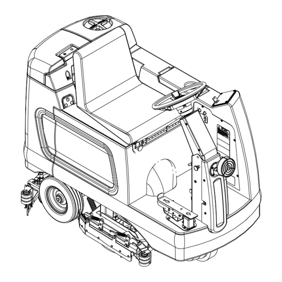
Page 10: Know Your Machine
KNOW YOUR MACHINE Recovery Tank Cover 12 Emergency Stop Switch / Battery Disconnect Solution Tank Fill Cover 13 Scrub Brush Deck And Side Skirts Operator Seat w/Safety Switch 14 Rear Wheel Solution Tank Drain Hose 15 Battery Compartment Steering Wheel Adj. Tilt Knob 16 Recovery Tank Shutoff Float Brake Pedal &... -
Page 11: Control Panel
CONTROL PANEL 23 Main Power Indicator 24 Solution System Fault Indicator 25 Scrub Off Button 26 Normal Scrub Button 27 Heavy Scrub Button 28 Solution System Indicator 29 Vacuum Button 30 Solution Button 31 Battery Condition Indicator 32 Hourmeter/Status Display 33 Master On/Off Key Switch 34 Scrub Mode Off Indicator 35 Normal Scrub Mode Indicator... -
Page 12: Functional Description Of Control Buttons
KNOW YOUR MACHINE FUNCTIONAL DESCRIPTION OF CONTROL BUTTONS: The controls on the HR 2800 / BR 700 were designed with one touch operation in mind. For single pass scrubbing the user can simply depress one button and all systems on the machine will be ready to go. For most single-pass scrubbing operations, the operator should only need to use the second row of three buttons on the control panel. -
Page 13: Description Of Indicators On The Control Panel
KNOW YOUR MACHINE Vacuum Button (29) - This button is used to select the mode of operation for the vacuum/squeegee system. There are 3 modes of operation for this system. These modes are OFF, AUTO, ON. Following is a description of each mode and how they are selected. OFF MODE: - In this mode the vacuum is off and the squeegee is in the up position. - Page 14 KNOW YOUR MACHINE DESCRIPTION OF INDICATORS ON THE CONTROL PANEL (CONTINUED) Vacuum System Indicator (37): • This indicator will be YELLOW if the vacuum/squeegee system is in the AUTO mode and the throttle is in the neutral position. This indicates that the vacuum system is enabled but the vacuum is currently off.
-
Page 15: Steering System
STEERING SYSTEM STEERING CHAIN REMOVAL AND TENSIONING Turn the master key switch off and disconnect the battery pack connector (12). See Figure 1. Loosen the (4) Hex HD Screws (A) and push the lower steering column back towards the driver seat to release the steering chain tension. -
Page 16: Wheel Drive System
WHEEL DRIVE SYSTEM WHEEL DRIVE MOTOR ASSEMBLY REMOVAL Turn the key switch (main power) to the OFF position and then disconnect the battery pack connector (12). On the side of the drive motor remove the motor wiring cover and observe the (2) wires (red & black) connected to the motor (terminal connections for reassembling). -
Page 17: Drive Tire Removal
WHEEL DRIVE SYSTEM DRIVE TIRE REMOVAL FIGURE 2 See Figure 2. Using a 6mm hex key wrench remove the (4) Soc. HD Screws (E) that secure the Steer Plate (F), Spindle Weldment (G) and Splash Guard (H) to the wheel motor mount then separate. -
Page 18: Brake Adjustment
WHEEL DRIVE SYSTEM BRAKE ADJUSTMENT Before making brake adjustment, inspect brake caliper and rotor for excessive wear and replace brake parts as needed. See Brake Pad Replacement section below, for instructions. See Figure 3. Loosen both the Locking Nuts (L) that secure the brake cable to the Mount Bracket (M) (located on the wheel motor). Note: The brake cable is threaded at both ends remove the brake cover on the left side of the steering column if replacement is needed (See Figure 1). -
Page 19: Potentiometer Removal & Testing
WHEEL DRIVE SYSTEM POTENTIOMETER REMOVAL AND TESTING WARNING! Disconnect the machine’s battery pack connector (12) before servicing. Potentiometer Removal See Figure 4. Remove the (3) Screws (U) securing the drive pedal mount assembly to the chassis then carefully lift the pedal assembly up and lay it on its side. -
Page 20: Potentiometer Installation & Adjustment
WHEEL DRIVE SYSTEM POTENTIOMETER INSTALLATION AND ADJUSTMENT The adjustment of the potentiometer is to set the drive pedal for a neutral drive motor operation. If the pot is not adjusted properly, the machine will creep in either FWD or REV. See Figure 4. -
Page 21: Scrub Brush System (Disc)
SCRUB BRUSH SYSTEM SCRUB BRUSH DECK REMOVAL (DISC) Lower the scrub deck with the scrub brushes installed. Don’t turn the key switch off until disconnecting the battery pack by using the emergency disconnect (12). This procedure is done to prevent the scrub deck from automatically raising when the key is turned off. -
Page 22: Scrub Brush Motor Removal
Note: Apply a small amount of grease or “Never Seize” to the gear box output shaft when reinstalling the drive Hub(s) (L). Note: The gearbox output shaft rotates the brush holders in the opposite direction of other Nilfisk-Advance auto scrubbers (see below). FRONT FRONT 20 - FORM NO. -
Page 23: Scrub Brush Gearbox Replacement
SCRUB BRUSH SYSTEM SCRUB BRUSH GEARBOX REPLACEMENT If the need to replace a disc scrub drive gearbox should arise, please follow the re-assembly instructions below. Installing the shaft keys-See Figure 3 Install (1) Shaft Key (U) into each end of motor shaft, you may need to use a hammer to complete this operation. Applying Never Seize Starting with the back-end of the motor. - Page 24 SCRUB BRUSH SYSTEM FIGURE 3 Leads at 12:00 Commutator End Back-End Apply Never Seize Shafts facing LEFT VIEW FIGURE 4 22 - FORM NO. 56043055 / HR 2800, HR 2800C / BR 700, BR 700C revised 2/05...
-
Page 25: Scrub Brush Skirt Replacement
SCRUB BRUSH SYSTEM SCRUB BRUSH SKIRT REPLACEMENT Disc and Cylindrical Side Skirt Maintenance General Overview The side skirt’s function is to channel the wastewater to the rear pick up squeegee, helping contain the water within the machine’s cleaning path. The skirt height adjustment is automatic on this system using spring tension and movable arms to control the blade pressure (See Figure 5). -
Page 26: Scrub Brush Lift Actuator Removal
SCRUB BRUSH SYSTEM SCRUB BRUSH LIFT ACTUATOR REMOVAL Lower the scrub deck with the scrub brushes installed. Don’t turn the key switch off until disconnecting the battery pack by using the emergency disconnect (12). This procedure is done to prevent the scrub deck from automatically raising when the key is turned off. -
Page 27: Scrub Brush System (Cylindrical)
SCRUB BRUSH SYSTEM (CYLINDRICAL) SCRUB BRUSH SYSTEM MAINTENANCE The scrubbing system must be serviced at regular intervals to maintain good scrubbing performance. Follow the maintenance steps listed below. Empty hopper and rinse clean any built up debris from the hopper drain holes (daily). Clean drain holes in the solution delivery trough on top of the scrub deck (weekly). -
Page 28: Scrub Brush Deck Assembly Removal
SCRUB BRUSH SYSTEM (CLYLINDRICAL) SCRUB BRUSH DECK ASSEMBLY REMOVAL Drain the solution tank. Lower the scrub deck with the cylindrical brushes installed. Attention: Don’t turn the key switch off until disconnecting the emergency battery disconnect (12) and then turn the key OFF. Note: This procedure is done to allow the scrub deck from automatically raising itself when the key is turned off. -
Page 29: Scrub Brush Motor Removal
SCRUB BRUSH SYSTEM (CYLINDRICAL) FIGURE 4 FIGURE 3 1 to 1-1/8" (25-29 mm) 7.36" (187 mm) 1-1/8" (29 mm) 1-1/8" (29 mm) Length of Assembled Rod SCRUB BRUSH MOTOR REMOVAL See Figure 5. Remove the Hairpin (R) and swing open the scrub deck skirt assembly and remove the Belt Guard (S) (4 screws). Loosen the scrub brush belt tension hardware at the Belt Idler (T) using a 5/8-inch and 11/16-inch wrenches. -
Page 30: Scrub Brush Belt Replacement
SCRUB BRUSH SYSTEM (CLYLINDRICAL) SCRUB BRUSH BELT REPLACEMENT See Figure 5. Remove Hairpin (S) and swing open the scrub deck skirt assembly (right or left side) and remove the belt guard(s) (P) (4 screws each). Important Service Tip: The left and right side drive belts are not the same lengths they must be ordered individually (P.N. 56407465, left side &... -
Page 31: Solution System
SOLUTION SYSTEM SOLUTION SOLENOID VALVE REMOVAL Location: The solenoid valve is mounted on top-middle of the scrub deck. Drain the solution tank using the solution tank drain hose (4). See Figure 1. Remove both the LH & RH Solution Hoses (A) & (B) at the solution Delivery Tubes (C). Loosen the hose clamp and remove the solution Feed Hose (D) from the barb fitting on the Solenoid Valve (E) (* see Service Tip Note). - Page 32 SOLUTION SYSTEM FIGURE 1 FRONT 30 - FORM NO. 56043055 / HR 2800, HR 2800C / BR 700, BR 700C revised 2/05...
-
Page 33: Recovery System
RECOVERY SYSTEM RECOVERY TANK REMOVAL Drain the recovery tank using the recovery tank drain hose. Disconnect the squeegee hose from the squeegee tool. Swing forward the seat to open and at the rear of the battery compartment disconnect the vacuum motor wiring harness. See Figure 1 below. -
Page 34: Vacuum / Recovery System Service Checklist
RECOVERY SYSTEM VACUUM / RECOVERY SYSTEM SERVICE MAINTENANCE CHECKLIST Whenever there is a vacuum problem, it’s best to check over the entire system. Use the checklist below as a guide, to thoroughly check the vacuum system. Clean built-up dirt from the inside of the squeegee tool. Replace the squeegee blades if they are nicked or torn. -
Page 35: Squeegee System
SQUEEGEE SYSTEM SQUEEGEE LIFT ACTUATOR MOTOR REMOVAL Lower the squeegee tool to the floor and disconnect the battery pack connector. See Figure 1. Remove the Retainer Ring (A) securing the Lift Cable Pin (B) and separate the cable from the squeegee mount. Disconnect the squeegee lift motor wire harness at the motor. -
Page 36: Squeegee Tool Angle And Height Adjustment
SQUEEGEE SYSTEM SQUEEGEE TOOL BLADE REPLACEMENT (CONTINUED) The squeegee blade has 4 working edges. Turn the blade so a clean, undamaged edge points toward the front of the machine. Replace the blade if all 4 edges are nicked, torn or worn to a large radius. Install the blade, following the steps in reverse order and adjust the squeegee. -
Page 37: Electrical System
Use a combination of multiple 2-volt cell units to construct a 24 Volt DC battery pack system. Nilfisk-Advance recommended battery pack capacity is a 395 AH @ 20 Hour Rate deep cycle battery system. Note: The battery pack must fit the battery compartment size listed below. -
Page 38: Description Of The Battery Condition Indicators
ELECTRICAL SYSTEM DESCRIPTION OF THE BATTERY CONDITION INDICATORS The battery condition indicators will give an indication of the state of charge of the batteries. The battery condition monitor will retain the state-of-charge even if the key has been turned off. The state-of-charge indication is reset to full charge when the batteries have been recharged. -
Page 39: Battery Maintenance
ELECTRICAL SYSTEM BATTERY MAINTENANCE Proper maintenance of electric vehicle batteries can greatly extend their life. Well-maintained batteries may last up to 3 years, but failure after 1 year is common if maintenance has been poor. There are 3 simple rules for good battery maintenance: •... -
Page 40: Actuator Drive Nut Adjustment
ELECTRICAL SYSTEM ACTUATOR DRIVE NUT ADJUSTMENT This manual section explains the steps for adjusting the drive nut settings for the machine’s two lift actuator motors. Reference the chart below to find the IN & OUT dimensional specification for the specific actuator motor needing adjustment. Part # Actuator Motor Drive Nut IN Position Drive Nut OUT Position... - Page 41 ELECTRICAL SYSTEM Instructions for Scrub Brush Lift Actuator Drive Nut Adjustment See Figure 4. On a new scrub lift actuator motor remove (spin-off) the Drive Nut (A) and install the short compression Spring (C) onto the actuator (lead screw) shaft first. Next reinstall the plastic drive nut as shown (with the nut pin pocket away from the motor). Follow steps 4-10 in the section labeled Instructions for Squeegee Lift Actuator Drive Nut Adjustment (reference previous page).
-
Page 42: Curtis Speed Control
ELECTRICAL SYSTEM CURTIS CONTROLLER The HR 2800 / BR 700 wheel drive system uses a .8 horsepower, 24V, DC permanent magnet motor. The system uses a Curtis Model 1235 solid-state controller to regulate the speed and direction of the drive wheel. The controller unit is located to the left of the operator seat, behind the louvered electrical access panel. - Page 43 ELECTRICAL SYSTEM STATUS LED FAULT CODES (TABLE 1) STATUS LIGHT EXPLANATION POSSIBLE CAUSE CODE DISPLAY Output fault 1. Short in motor or in motor wiring. 2. Controller failure. Overcurrent fault 1. Short in motor or in motor wiring. 2. Controller failure. EEPROM fault 1.
-
Page 44: Main Control Board Functional Overview
ELECTRICAL SYSTEM FUNCTIONAL OVERVIEW OF MAIN CONTROL BOARD The primary function of the main control board is to position the scrubbing brush(s) with respect to the floor surface using a lift actuator motor to maintain the correct brush pressure and current draw of the brush motor. When the normal scrub or heavy scrub switch is depressed this will lower the scrub deck to the operating position and by activating the foot pedal start the brush motor. - Page 45 ELECTRICAL SYSTEM MAIN CONTROLLER ERROR CODES (CONTINUED) Error Code Fault Description Troubleshooting Action Err06 Brush lift actuator open circuit (**) Check for disconnected actuator wiring, open in wiring or defective actuator motor. Repair or replace. Err07 Brush motor overload Check for binding in rotation of brushes or improper brush lift actuator operation.
- Page 46 ELECTRICAL SYSTEM MAIN CONTROLLER ERROR CODES (CONTINUED) Error Code Fault Description Troubleshooting Action Err18 Squeegee actuator overload Check for binding of squeegee lift linkage and exces- sive weight on squeegee. Repair Err19 Squeegee actuator severe overload Check for binding or frozen squeegee lift linkage and excessive weight on squeegee.
- Page 47 ELECTRICAL SYSTEM ADDITIONAL ERROR CODE TROUBLESHOOTING INFORMATION When entering the main controller error fault recall mode and a fault Err01 or Err02 has been detected, the service person may see a second set of error codes. Refer to the chart below that shows the additional fault error codes by machine system. These secondary codes give information on a specific failure that is internal on the control board circuit.
-
Page 48: Main Control Board Special Program Options For Machines Before Sn 1362502
ELECTRICAL SYSTEM MAIN CONTROL BOARD SPECIAL PROGRAM OPTIONS FOR MACHINES BEFORE SE- RIAL NUMBER 1362502 SELECTION OF LOW VOLTAGE CUTOUT THRESHOLD: The HR 2800 / BR 700 is equipped a low voltage cutout feature to prevent over-discharging the batteries. This feature will automatically shut down the scrub system when the battery voltage falls to the selected threshold. - Page 49 ELECTRICAL SYSTEM MAIN CONTROL BOARD SPECIAL PROGRAM OPTIONS FOR MACHINES BEFORE SERIAL NUMBER 1362502 (CONTINUED) RECALL OF STORED ERROR (FAULT) CODES: Whenever an electrical system fault is detected by the main control unit, one or more error codes are displayed and stored by the control unit.
- Page 50 ELECTRICAL SYSTEM MAIN CONTROL BOARD SPECIAL PROGRAM OPTIONS FOR MACHINES BEFORE SERIAL NUMBER 1362502 (CONTINUED) VACUUM OFF WHEN SCRUB OFF SWITCH PRESSED OPTION: Normally, when the scrub system is turned off the vacuum is left on to allow recovery of any solution left on the floor and solution that will drip off of the scrub brushes/pads.
- Page 51 ELECTRICAL SYSTEM MAIN CONTROL BOARD SPECIAL PROGRAM OPTIONS FOR MACHINES BEFORE SERIAL NUMBER 1362502 (CONTINUED) ENABLING OR DISABLING FAULT DETECTION: Normally, the main control unit will perform checks of the electrical system during operation. If a fault occurs in a particular system that system (and possibly others) will be shut down.
- Page 52 ELECTRICAL SYSTEM MAIN CONTROL BOARD SPECIAL PROGRAM OPTIONS FOR MACHINES AFTER SERIAL NUMBER 1362501 SCRUB MODE DESCRIPTION: On the 2800/BR700, both the normal and heavy scrub modes are independently programmable to have user adjustable or fixed scrub pressure settings. If the adjustable option is selected (factory default), the operator will be able to vary the amount of scrub pressure while operating the machine.
-
Page 53: Main Control Board Special Program Options For Machines After Sn 1362501
ELECTRICAL SYSTEM MAIN CONTROL BOARD SPECIAL PROGRAM OPTIONS FOR MACHINES AFTER SERIAL NUMBER 1362501 (CONTINUED) SCRUB MODE PROGRAMMING FOR USER ADJUSTABLE SCRUB PRESSURE: To program the normal scrub mode for user adjustable scrub pressure perform the following steps: Turn the master key switch off. Press and hold the normal scrub button. - Page 54 ELECTRICAL SYSTEM MAIN CONTROL BOARD SPECIAL PROGRAM OPTIONS FOR MACHINES AFTER SERIAL NUMBER 1362501 (CONTINUED) To program the heavy scrub mode for fixed scrub pressure perform the following steps: Turn the master key switch off. Press and hold the heavy scrub button. Turn the master key switch on while continuing to hold the heavy scrub button until the status display shows “PA * “, where * is a number from 2 to 9.
- Page 55 ELECTRICAL SYSTEM MAIN CONTROL BOARD SPECIAL PROGRAM OPTIONS FOR MACHINES AFTER SERIAL NUMBER 1362501 (CONTINUED) RECALL OF STORED ERROR (FAULT) CODES: Whenever an electrical system fault is detected by the main control unit, one or more error codes are displayed and stored by the control unit.
- Page 56 ELECTRICAL SYSTEM MAIN CONTROL BOARD SPECIAL PROGRAM OPTIONS FOR MACHINES AFTER SERIAL NUMBER 1362501 (CONTINUED) VACUUM OFF WHEN SCRUB OFF SWITCH PRESSED OPTION: FACTORY DEFAULT: ON Normally, when the scrub system is turned off the vacuum is left on to allow recovery of any solution left on the floor and solution that will drip off of the scrub brushes/pads.
- Page 57 ELECTRICAL SYSTEM MAIN CONTROL BOARD SPECIAL PROGRAM OPTIONS FOR MACHINES AFTER SERIAL NUMBER 1362501 (CONTINUED) RAMP MODE FEATURE: Under normal conditions the operator will use the throttle for accelerating and decelerating/stopping. This works well unless the machine is used to scrub on an inclined surface. In this case, using the throttle to decelerate (such as braking while going down hill) will cause the squeegee to raise and the solution flow to shut off;...
-
Page 58: Service Test Mode For Machines After Sn 1362501
ELECTRICAL SYSTEM SERVICE TEST MODE FOR MACHINES AFTER SERIAL NUMBER 1362501 To assist in the troubleshooting and servicing of the electrical system and related components on the 2800/BR700 scrubbers, a special test mode which allows independent control of the various outputs and monitoring of the various inputs has been incorporated. To enter the service test mode perform the following steps: Turn the master on/off key switch to the off position. - Page 59 ELECTRICAL SYSTEM SERVICE TEST MODE FOR MACHINES AFTER SERIAL NUMBER 1362501 (CONTINUED) Horn Switch (20): This switch is used to momentarily activate either the pad/brush lift actuator or the squeegee lift actuator. See the descriptions below for more details. Scrub Off Switch (15): This switch is used to toggle the state of the pad/brush motor.
- Page 60 ELECTRICAL SYSTEM SERVICE TEST MODE FOR MACHINES AFTER SERIAL NUMBER 1362501 (CONTINUED) Heavy Scrub Switch (17): This switch is used to control the output to the squeegee lift actuator. Pressing and releasing this switch will cycle the actuator output through 4 states. These are: 1 - output off, direction = up 2 - output on, direction = down 3 - output off, direction = down...
-
Page 61: Electrical Component Location
ELECTRICAL SYSTEM COMPONENT LOCATION Item Description Control Box Assembly (Main) & Controller, Speed Contactor (Brush Motor) Contactor (Vac Motor) 150 Amp Fuse Wheel Motor Horn / Back-Up Alarm Water Solenoid Valve Brush, Lift Actuator Motor Squeegee, Lift Actuator Motor Vac Motor Brush Motor (Disc) Brush Motors (Cylindrical) Throttle Potentiometer... -
Page 62: Wiring Schematic
ELECTRICAL SYSTEM CIRCUIT CIRCUIT MAIN BREAKER BREAKER SWITCH (AUX. 10 AMP) (DRIVE 45 AMP) WHT/BLU 96A-B ORN/BLU 36A-B BLK/WHT 09A-B VIO/WHT 79A-B WHT/ORN 93A-B GRN/BLK 50A-B ORN/BLK 30A-B RED/BLK 20A-B BLK OF-B ORN/RED 32A-B DISPLAY BOARD RED/BRN 21A-B RED/BRN 21B-B RED/BRN 21C-B RED/BRN 21D-B MAIN CONTROL... -
Page 63: Wiring Diagram
ELECTRICAL SYSTEM SCHEMATIC / WIRING DIAGRAM Controller, Speed Valve, Solution Solenoid Main Control Board Display PCB Assembly Lift Actuator (Brush) Lift Actuator (Squeegee) Battery, 24V Motor (Vac) Motor, Brush (Disc) – (Cylindrical) Diode Motor, Wheel Drive Diode Motor, Brush (Cylindrical Only)* Fuse Clamp, 150 Amp Thermistor Circuit Breaker, 10 Amp (Control) - Page 64 Austria (Sales Sub) Holland (Sales Sub) Nilfi sk-Advance GmbH Phone: +43 Nilfi sk-Advance B.V. Phone: +31 Voralberger Allee 46 1616 58 30 22 Camerastraat 9 (2e verdieping) 36 546 07 00 A-1230 Wien Fax: +43 1322 BB Almere Fax: +31 info@nilfi...
- Page 65 Sweden (Prod.) Hong Kong (Sales Sub) Nilfi sk-Advance A/S Phone: +46 Nilfi sk-Advance Ltd. Phone: +852 Åmål Branch 5321 7500 2001 HK Worsted Mills Ind’l Bldg., 2427 5951 Strömsbergsgatan Fax: +46 31-39 Wo Tong Tsui St. Fax: +852 Box 127 5321 7595 Kwai Chung, Hong Kong 2487 5828...
- Page 66 © 2005 Printed in USA...
Need help?
Do you have a question about the Hydro-Retriever 2800 BR700 and is the answer not in the manual?
Questions and answers