
Related Manuals for Tvone C2-2000 Series


Summary of Contents for Tvone C2-2000 Series
- Page 1 C2-2000 / C2-2000A S ERIES PERATION ANUAL C2-2000 / C2-2000A Series Video Processor Operation Manual...
- Page 2 C2-2000 / C2-2000A S ERIES PERATION ANUAL...
-
Page 3: Table Of Contents
C2-2000 / C2-2000A S ERIES PERATION ANUAL TABLE OF CONTENTS DISCLAIMER ....................1 Regulatory Agency Acceptance................1 FCC Statement....................1 Manual Version Information................. 2 Manual Copyright Notice ..................2 IMPORTANT SAFETY INSTRUCTION............3 CAPABILITY, DEVICE FEATURES AND PRODUCT FEATURES..... 13 Device Capabilities.................... - Page 4 C2-2000 / C2-2000A S ERIES PERATION ANUAL The High Level Menu Structure ................. 28 Group Names and Descriptions................. 29 Items Associated with the Adjust outputs group..........30 Items Associated with the Adjust windows group..........32 9.4.1 Extended scaling controls.................. 35 9.4.2 ‘Aspect adjust’...
- Page 5 C2-2000 / C2-2000A S ERIES PERATION ANUAL 13.1 Introduction ....................... 72 13.2 Edge-blending requirements................73 13.3 Basic setup of the two projectors............... 74 13.4 Connections to the scaler(s) and projectors............74 13.5 Initial setup ......................75 13.6 Edge-blending activation ................... 76 13.7 Edge-blending overlap / size ................
- Page 6 C2-2000 / C2-2000A S ERIES PERATION ANUAL 15.6 Some colors appear to be incorrect on the CV/YC output........98 15.7 How can I reduce color smearing on CV connections?........98 15.8 I can no longer adjust the Output image resolution..........98 15.9 The picture on the video display is black and white...........
-
Page 7: Disclaimer
C2-2000 / C2-2000A S ERIES PERATION ANUAL DISCLAIMER This product is intended for professional and/or home use. This product is not intended for use in a medical environment and does not have the required certifications for such use. Similarly, use aboard any aircraft or spacecraft while in flight or as an adjunct to any surface, airborne or marine navigation system or any offshore marine activity, including control of any watercraft, or any use similar to those specifically herein mentioned is prohibited. -
Page 8: Manual Version Information
C2-2000 / C2-2000A S ERIES PERATION ANUAL Caution: This equipment is intended for use in the manner prescribed in the Instruction Manual. Any user changes or modifications not expressly approved by TV One Multimedia Solutions could void the user’s authority to operate the equipment. -
Page 9: Important Safety Instruction
C2-2000 / C2-2000A S ERIES PERATION ANUAL IMPORTANT SAFETY INSTRUCTION To insure the best from this product, please read this manual carefully. Keep it in a safe place for future reference. To reduce the risk of electric shock, do not remove the cover from the unit. No user serviceable parts inside. - Page 10 C2-2000 / C2-2000A S ERIES PERATION ANUAL 2.5 Ventilation Slots and openings in the sides of the unit are provided for ventilation. To ensure reliable operation, avoid obstruction of these openings and ensure the unit is installed in a well-ventilated area. 2.6 Intellectual property Some IC chips in this product include confidential and/or trade secret property.
- Page 11 C2-2000 / C2-2000A S ERIES PERATION ANUAL 2 IMPORTANT: CONSIGNES DE SECURITE Afin de tirer le meilleur de ce produit, merci de lire attentivement ce manuel. Gardez-le dans un endroit sûr pour pouvoir le consulter à nouveau. Afin de réduire le risque de choc électrique, ne retirez pas l’unité de sa protection. Aucune pièce réparable par l’utilisateur à...
- Page 12 C2-2000 / C2-2000A S ERIES PERATION ANUAL L’installation de cette unité doit se faire dans un endroit frais et sec, éloigné de sources excessives de chaleur, de vibrations, de poussière, d’humidité et de froid. 2.5 Aération Les rainures et les ouvertures sur les cotés de l’unité servent à l’aérer. Pour permettre une utilisation sûre, évitez d’obstruer ces ouvertures et assurez-vous que l’unité...
-
Page 13: Instrucciones Importantes De Seguridad
C2-2000 / C2-2000A S ERIES PERATION ANUAL 2 INSTRUCCIONES IMPORTANTES DE SEGURIDAD Para sacar el mejor provecho de este producto, léase este manual con detenimiento. Guárdelo en un lugar seguro para poder hacerle referencia en el futuro. Para reducir el riesgo de calambre, no quite la cubierta del aparato. No hay piezas utilizables dentro. - Page 14 C2-2000 / C2-2000A S ERIES PERATION ANUAL 2.4 Ubicación Este aparato se debe instalar en un lugar seco y fresco, lejos de fuentes de calor excesivas, la vibración, el polvo, la humedad y el frío. 2.5 Ventilación El aparato viene provisto de ranuras y agujeros en los lados para la ventilación. Para asegurar una operación eficaz, se debe evitar la obstrucción de estos agujeros y también asegurar que el aparato se instale en una zona con adecuada ventilación.
- Page 15 C2-2000 / C2-2000A S ERIES PERATION ANUAL 2 WICHTIGE SICHERHEITSVORSCHRIFTEN Lesen Sie diese Bedienungsanleitung bitte sorgfältig, um Ihr Produkt optimal nützen zu können, und bewahren Sie sie zum späteren Nachschlagen an einem sicheren Ort auf. Entfernen Sie bitte keinesfalls die Abdeckung, um der Gefahr eines Stromschlags vorzubeugen.
- Page 16 C2-2000 / C2-2000A S ERIES PERATION ANUAL 2.3 Aufstellung Das Gerät sollte an einem kühlen, trockenen Ort aufgestellt werden, fern von übermäßiger Wärme, Vibrationen, Staub, Feuchtigkeit und Kälte. 2.5 Belüftung Seitliche Schlitze und Öffnungen sorgen für die Belüftung des Geräts. Um die ordnungsgemäße Belüftung zu gewährleisten, dürfen diese Öffnungen nicht verdeckt werden.
- Page 17 C2-2000 / C2-2000A S ERIES PERATION ANUAL 2 BELANGRIJKE VEILIGHEIDSINSTRUCTIES Lees deze handleiding zorgvuldig door om het beste uit uw product te halen. Bewaar het op een veilige plek voor raadpleging in de toekomst. Haal nooit het omhulsel van de eenheid af, dit om de kans op een elektrische schok te verminderen.
- Page 18 C2-2000 / C2-2000A S ERIES PERATION ANUAL 2.4 Plaatsing Deze eenheid moet geïnstalleerd worden op een koele droge plaats, uit de buurt van bronnen van extreme hitte, vibraties, stof, vocht en kou. 2.5 Ventilatie De sleuven en openingen aan de zijkant van de eenheid zijn voor ventilatie. Zorg er voor dat de eenheid op een goed geventileerde plek geïnstalleerd wordt zodat deze betrouwbaar werkt.
-
Page 19: Capability, Device Features And Product Features
PERATION ANUAL CAPABILITY, DEVICE FEATURES AND PRODUCT FEATURES Device Capabilities ® The C2-2000 series uses the proprietary CORIO 2 Engine to perform its functions, ® ® being the second generation of the successful CORIO products. The CORIO technology is a powerful toolset for any application requiring high quality video signal conversion or image manipulation. -
Page 20: Device Features
Ultimate flexibility The C2-2000 series’ output signal format flexibility assures that the Native Resolution of virtually any display can be matched. Because of the resolution calculator (included in the Windows® Control Panel), even new resolutions can be added to the unit. - Page 21 C2-2000 / C2-2000A S ERIES PERATION ANUAL ® heart of the image processing hardware – the CORIO 2 scaling engine. See http://www.tvone.com/support for more detail.
-
Page 22: Product Images
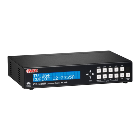
C2-2000 / C2-2000A S ERIES PERATION ANUAL PRODUCT IMAGES Your C2-2000 product should look like one of the units below. C2-2000A models look identical, except for the C2-2355A model which has dual SDI connections. Each unit has a different main function (Down Converter, Video Scaler, Universal Scaler) and a subsequently different ability to process video signals. -
Page 23: Front Panel Controls
The range of buttons on the front of the unit provides the user with quick access for selecting a variety of inputs and features. Since all the units in the C2-2000 series are different, not all of the descriptions below will be applicable to the unit in question. -
Page 24: Multi-Directional Switch
C2-2000 / C2-2000A S ERIES PERATION ANUAL LOCK Sets Lock mode to Genlock. This locks the unit’s output to the current Lock source. See ‘Adjust outputs’ menu details. Sets Lock mode to Lock & Mix, to overlay onto the current Lock source. -
Page 25: Factory Reset
C2-2000 / C2-2000A S ERIES PERATION ANUAL 5.3.3 Factory Reset If you wish to restore all operational parameters to their original condition (for example, if saved settings prevent the unit from working with your display monitor), hold the STANDBY/ON and the multi-directional switch in together until two beeps are heard. -
Page 26: Forcing Default Output Resolution
C2-2000 / C2-2000A S ERIES PERATION ANUAL 5.3.7 Forcing default output resolution Press and hold the RGB button and button 3 together, then release. The default output resolution depends on the type of unit you have – see above. -
Page 27: Video Inputs And Outputs
PERATION ANUAL VIDEO INPUTS AND OUTPUTS The C2-2000 series has a number of different inputs and outputs – see earlier front and rear panel diagrams to see what is available on your unit. Computer & Video inputs PC/HD inputs can accept: ... -
Page 28: Computer & Video Outputs
C2-2000 / C2-2000A S ERIES PERATION ANUAL Enhanced ‘A’ units also accept HD-SDI (1.485Gbit/s) on their SDI inputs. Computer & Video outputs The PC/HD output can use: Analog RGBHV RGsB (sync on green) RGBS (separate sync at TTL levels) ... - Page 29 C2-2000 / C2-2000A S ERIES PERATION ANUAL On the back of audio-equipped units are 5 x 3-way connector blocks. These can be removed individually (with care), or can be left in-situ whilst connections are made (by releasing each terminal using a small screwdriver, and then by clamping it back down again once a new cable has been inserted).
-
Page 30: Unpacking And Installation
C2-2000 / C2-2000A S ERIES PERATION ANUAL UNPACKING AND INSTALLATION Shipping Carton Your unit will arrive double boxed for maximum protection during shipping. You are encouraged to retain both boxes and all packing material so the unit can be returned in the unlikely event that repairs should ever become necessary. Important Safety Instructions The AC power adaptor furnished with the unit should conform to the type in use in your country. -
Page 31: Initial Operation And Test Of Video Scalers
C2-2000 / C2-2000A S ERIES PERATION ANUAL Disconnect the cable going from a Personal Computer’s Monitor to the Personal Computer. Connect the output from the PC video card (the PC connector formerly used by the monitor cable) to the PC input on the rear panel of the unit. Next, take the cable from the PC monitor and connect it to the PC/HD output –... - Page 32 C2-2000 / C2-2000A S ERIES PERATION ANUAL Next, take the cable from the PC monitor and connect it to the PC/HD output. Then connect the AC Power Adaptor to a working AC outlet, turn on the PC, monitor and then your unit. Provided you have not changed anything from the Factory Defaults and the monitor will display output 1024x768 @ 60Hz, then your PC output will be seen on the PC monitor –...
-
Page 33: Infra-Red Remote Control
C2-2000 / C2-2000A S ERIES PERATION ANUAL INFRA-RED REMOTE CONTROL Your unit is compatible with an optional infra-red remote control as shown below: Resets back to power-on defaults Stores current Selects input: settings 1/2/3=RGB/CV/YC Enables Keyer Enables Lock & Mix mode Fades in/out Starts AutoSet Locks the... -
Page 34: Menu Layout And Settings Adjustment
C2-2000 / C2-2000A S ERIES PERATION ANUAL MENU LAYOUT AND SETTINGS ADJUSTMENT From here on, we’ll be looking at the menu structure employed in the C2-2000 series and, more importantly, the individual menu items that allow you to take advantage of the power of the unit. You’ll be using the multi-directional switch and the Liquid Crystal Display (LCD) to view the options and settings available to you. -
Page 35: Group Names And Descriptions
CORIO2 TV One The first is the ‘welcome’ display shown above indicating the model of the unit. www.tvone.com SW: 65. PT: 12, BT: 13 Moving to the next menu item displays the firmware information screen (the numbers on your unit will be different to those shown). The SW number refers to the version of firmware loaded into the unit, this can be upgraded from the support website. -
Page 36: Items Associated With The Adjust Outputs Group
C2-2000 / C2-2000A S ERIES PERATION ANUAL Items Associated with the Adjust outputs group This menu group allows adjustments to be made that specifically affect the output of the unit, including output resolution and locking/overlaying onto a computer or video source. 800 x 600 60Hz Lock mode [Off] [RGB1]... - Page 37 C2-2000 / C2-2000A S ERIES PERATION ANUAL Your unit can handle a very wide array of inputs and convert them all to a single output signal with defined characteristics. This output resolution will remain in place until changed or it may be overridden by the lock mode and source. The top line of the display will show the current output resolution selected.
-
Page 38: Items Associated With The Adjust Windows Group
C2-2000 / C2-2000A S ERIES PERATION ANUAL This menu item is only available on certain units when the Output resolution is set to PAL or NTSC. With this you can change the output filtering system to increase or decrease the image sharpness. In general, high sharpness can result in increased colour disturbance. - Page 39 C2-2000 / C2-2000A S ERIES PERATION ANUAL Adjust windows Zoom level % [ 100] Changing this option, sets the amount of picture magnification you wish to use for the window Source. You are provided with the options to zoom the image from 100% to 1000% (10x zoom).
- Page 40 C2-2000 / C2-2000A S ERIES PERATION ANUAL Note that some units do not have the [On] entry – this is only for units with a PIP button on the front, with turns this entry On and Off. On these units, this feature is ‘Off’...
-
Page 41: Extended Scaling Controls
C2-2000 / C2-2000A S ERIES PERATION ANUAL Disables flicker reduction (sharpest mode). Suitable for most input sources. Med. Enough for most situations such as thin line drawings High Highest amount of flicker reduction. Will cause loss of vertical detail in some images. Adjust windows Image smoothing [Auto]... -
Page 42: Aspect Adjust' = 'Advanced
C2-2000 / C2-2000A S ERIES PERATION ANUAL In ‘Pixel’ mode, the user has direct access to pixel and line-accurate scaling functions. This lets the user specify the exact co-ordinates and size of the source image (within the video source), and the position and size of where this is placed in the output video signal. -
Page 43: Aspect Adjust' = 'Pixel
C2-2000 / C2-2000A S ERIES PERATION ANUAL 9.4.3 ‘Aspect adjust’ = ‘Pixel’ Adjust windows [ 0] , 0 640, 480 Adjust windows [ 0] , 0 640, 480 This menu items work together to specify the exact co-ordinates and size of the source image (within the video source) and the position and size of where this is placed in the output video signal. - Page 44 C2-2000 / C2-2000A S ERIES PERATION ANUAL Adjust keyers Swap fore/backgrnd [Off] This menu item is only present on single-channel scalers – dual-channel scalers have the layer priority set within the ‘Adjust Windows’ menu. This menu item allows you to swap the foreground and background images when Lock mode is set to Lock &...
-
Page 45: Edge Blend Items Within The Adjust Keyers Group
C2-2000 / C2-2000A S ERIES PERATION ANUAL the keying of images varies depending on how close a color is to the keyed-out range. Adjust keyers Y Key invert [Off] The Y Key invert changes the keying characteristics with respect to what colors of the foreground image you wish to ‘key out’. -
Page 46: Items Associated With The Adjust Sources Group
C2-2000 / C2-2000A S ERIES PERATION ANUAL Adjust keyers E.blnd gam. [1.00] x [1.00] This controls the gamma for the blend width and height respectively. Left and Right blend gamma values are adjusted together by the first number, and Top and Bottom blend gamma values are adjusted together by the second number. -
Page 47: Menu Items Common To All Inputs
C2-2000 / C2-2000A S ERIES PERATION ANUAL CV / YC type sources. 9.7.1 Menu items common to all inputs Source: RGB1 TL pos. adj. [ 0] [ 0] This menu item allows manual positioning of the Top and Left portion of the image. It is used to ensure that the input signal is captured correctly, eliminating any black borders. - Page 48 C2-2000 / C2-2000A S ERIES PERATION ANUAL This option is used to tell the unit what to do if the video source is lost or becomes unstable. Options are: Option Description Show Shows all picture break-up and instabilities. Freeze Freezes the latest frame – un-freezes as soon as the source becomes stable again.
-
Page 49: Rgb Source Menu Items
C2-2000 / C2-2000A S ERIES PERATION ANUAL on moving images, however is not suitable for noisy sources where the noise could be mis-interpreted as a diagonal or sloping element of the picture. 9.7.2 RGB Source Menu Items Source: RGB1 Autoset status [Inactive] Once the Autoset sense setting has been made, this menu item is accessed and activated. -
Page 50: Cv & Yc Source Menu Items
C2-2000 / C2-2000A S ERIES PERATION ANUAL This menu item lets you adjust the individual RGB or YUV/YPbPr signals, in case one component is at a different contrast to other, or if they all need to be boosted or lowered. 9.7.3 CV &... -
Page 51: Testcard Source Menu Items
C2-2000 / C2-2000A S ERIES PERATION ANUAL 9.7.4 Testcard Source Menu Items Source : TC1 Testcard [ 0] This item is only available for units supporting Testcards (TC) sources. Used to select the Testcard from memory to use as a source for the Testcard currently selected. -
Page 52: Items Associated With The Adjust Buttons Group
C2-2000 / C2-2000A S ERIES PERATION ANUAL Wipe Size sets the ‘granularity’ of the ‘Wipe’ effect and so is only shown when ‘Wipe’ is the transition type. The smaller the number, the more elements there are to the wipe. To clarify by example, if you select the Diamond wipe effect and set a small number into the Wipe Size parameter, you will have a large number of Diamonds present in the transition. -
Page 53: Items Associated With The Adjust Ethernet Group
C2-2000 / C2-2000A S ERIES PERATION ANUAL 9.10 Items associated with the Adjust ethernet group (Please note that not all units have this sub-menu.) Your unit can be remotely controlled via its RS-232 serial port, but some units can also be controlled via a Local Area Network using the Ethernet connector. This provides TCP/IP communications to and from the unit using a custom protocol. -
Page 54: Items Associated With The Adjust Resolutions Group
C2-2000 / C2-2000A S ERIES PERATION ANUAL Enter the IP port number you wish the unit to communicate on. Keep a note of this as it will be needed when using other devices to communicate with the unit e.g. CC- 300. - Page 55 C2-2000 / C2-2000A S ERIES PERATION ANUAL Typically, the image number currently being used for input or output would be already be selected otherwise immediate feedback to your changes will not be available via your monitor. 800 x 600 60 Hz Interlaced [ Off] This adjustment specifies whether the image is interlaced or progressive scan.
- Page 56 C2-2000 / C2-2000A S ERIES PERATION ANUAL 800 x 600 60 Hz H/V active [ 800] x 600 A video frame includes both the active area, the portion of the image normally containing useful visual information, and a resolution value for a given display standard which only expresses the number of pixels visible in an image.
-
Page 57: Items Associated With The System Group
C2-2000 / C2-2000A S ERIES PERATION ANUAL 800 x 600 60 Hz Sync polarity [+H+V] Sync can be either negative polarity or positive polarity. To further complicate things, it is possible that you may want to make the Horizontal Sync polarity different from the Vertical Polarity. - Page 58 C2-2000 / C2-2000A S ERIES PERATION ANUAL System TAC# 27-AA-1C-93-F8-33 The TAC number is a unique identifier for the unit and is for use with the PPF value below. System PPF# 1A-67-2B-9D-50-4F The PPF number is for units that support the ‘Pay Per Feature’ system. Extra features in the unit (such as Mix and Key) may be activated using this menu tiem by entering in the correct numbers and re-starting the unit.
- Page 59 C2-2000 / C2-2000A S ERIES PERATION ANUAL System RS232 baud rate [57600] This menu item allows the adjustment of the serial baud rate used for RS-232 communications. The rate can be adjusted to 9600, 19200, 28800, 33600, 38800, 57600 and 115200. (This adjustment is provided for those instances where you wish to use the RS-232 control system for your own purposes.) The default baud rate is 57600.
- Page 60 C2-2000 / C2-2000A S ERIES PERATION ANUAL System Firmware updates Indicates the total number of times the firmware has been changed over the life of the unit. It is quite possible for this to be more than 1, as a unit undergoes numerous tests during production.
-
Page 61: Rs232 Port
C2-2000 / C2-2000A S ERIES PERATION ANUAL RS232 PORT 10.1 Connection Your unit is fitted with a standard ‘D9’ plug or socket allowing it to be controlled from a computer or other type of terminal or console with a similar interface. Most computers fitted with an RS232 port, known as a ‘COM’... - Page 62 C2-2000 / C2-2000A S ERIES PERATION ANUAL...
-
Page 63: Rs232 / Ip Control Specification
C2-2000 / C2-2000A S ERIES PERATION ANUAL RS232 / IP CONTROL SPECIFICATION PLEASE NOTE: Not all units support RS232 and/or IP (Ethernet) communications – check to see if this feature is present on your unit. This section outlines how to control a unit via an RS232 or Ethernet link (if fitted to your unit), using ASCII-based commands. -
Page 64: Packet Format
C2-2000 / C2-2000A S ERIES PERATION ANUAL The ACK flag will be returned as 0 if the command is invalid for some reason – for example a bad FUNCTION, WINDOW, OUTPUT or PAYLOAD value. An ACK=0 message will be otherwise identical to the one you sent, so you know exactly which message has the error. - Page 65 C2-2000 / C2-2000A S ERIES PERATION ANUAL returned means message was okay. ACK=0 returned means an error was present in the message. Bit 5 = 0 Reserved for future use. Bit 4 = 0 Reserved for future use. Bit 3 = 0 Reserved for future use. Bit 2 = 1 This bit *must* be set.
-
Page 66: Function List
C2-2000 / C2-2000A S ERIES PERATION ANUAL ASCII-hex byte that is the (check) sum of all previous bytes (excluding the SOP 'F' character). E.g. The command F0400410082000001C8 has the checksum of 04+00+41+00+82+00+00+01=C8, so the complete command to send is F0400410082000001C8. A short-cut for debugging allows the checksum to be replaced by 2 question marks, so in the previous example you could send F0400410082000001?? Instead. - Page 67 C2-2000 / C2-2000A S ERIES PERATION ANUAL Adjust outputs Output enable 0=Blanked, 1=Active Lock source (connector) 0x10 to 0x1F = RGB1 to RGB16 0x30 to 0x3F = CV1 to CV16 0x40 to 0x4F = YC1 to YC16 0x50 to 0x5F = SDI1 to SDI16 0xD0 = OUT1, 0xD1 = OUT2 0xF0 = TC1, 0xF1 = TC2 Lock method...
- Page 68 C2-2000 / C2-2000A S ERIES PERATION ANUAL AES/SDI Chan. 1 source 0x00 to 0x07 = SDI1-1 to SD1-8 AES/SDI Chan. 2 source 0x08 to 0x0F = SDI2-1 to SDI2=8 0x10 to 0x1F = AES1 to AES16 AES/SDI Chan. 3 source 0x20 = AFV (audio follow video) AES/SDI Chan.
- Page 69 C2-2000 / C2-2000A S ERIES PERATION ANUAL Flicker reduction 0..3 = Off, Low, Med, High Image smoothing 0..2 = Off, Med, High Image flip 0..3 = Off, Horiz., Vertical, H & V Temporal interpolation 0..1 = Off, On Max fade level 0..100 = Fade level % Fade out / in -1 = Fade out...
- Page 70 C2-2000 / C2-2000A S ERIES PERATION ANUAL Max fade level 0..100% Layer priority 0..5 Borders (on certain models only) Border enable 0..1 = Off, On Border H size 0..99 Border V size 0..99 Border H offset 0..99 Border V offset 0..99 Border Opacity 0 (fully transparent) ..100 (solid)
- Page 71 C2-2000 / C2-2000A S ERIES PERATION ANUAL Contrast 30..5F 0BC 0..180 Saturation 30..5F 0B9 0..180 30..5F 0BA -180..180 Sharpness 30..5F 080 -7..+7 Luma delay 30..5F 0BD -4..3 Field swap 10..FF 0C9 0..1 = Off, On (swaps odd/even fields) Field Offset 10..FF 196 0..7 = -4..+3 (defaults to 4 = 0) For units with digital audio processing:...
- Page 72 C2-2000 / C2-2000A S ERIES PERATION ANUAL H.freq.crse 10000..200000 H.freq.fine 10000..200000 H/V active (H) 64..2047 H/V active (V) 64..2047 H/V start (H) 0..1023 H/V start (V) 0..1023 Clks/l 64..4095 Lines/f 64..2047 H/V sync (H) 8..1023 H/V sync (V) 1..1023 Sync polarity 0..3 = ++, +-, -+, -- System SW (Software version)
-
Page 73: Examples
C2-2000 / C2-2000A S ERIES PERATION ANUAL Front panel lock 0 = unlocked, 1 = locked 11.4 Examples Each example shows the packet sent to the unit and its response. When a byte is not required to be sent it is indicated by a ‘- ‘in the table below (since a Read is 6 bytes shorter than a Write). -
Page 74: Reading A Previously Stored Macro
C2-2000 / C2-2000A S ERIES PERATION ANUAL The CHA byte indicates the macro we are programming / reading / running. Macro 1 to 5 are CHA 0..4, CHA=5 is restore, CHA 6..7 are Macros 6..7. Macro Restore (CHA=5) is read only, the units restore state is set by sending the Store command (0C8). -
Page 75: Writing To A Macro
C2-2000 / C2-2000A S ERIES PERATION ANUAL 11.5.2 Writing to a macro In order to read a preset / macro the following commands must be sent in this specific order – no other commands should be sent between these messages. Packet sent Packet returned SOP CMD CHA WIN OUT FUN PAY... -
Page 76: Common Operations
C2-2000 / C2-2000A S ERIES PERATION ANUAL COMMON OPERATIONS This section provides step by step instructions for some common operations. 12.1 Operation of the Keyer Some units come equipped with a very powerful Luminance and Chrominance Keyer. The Keyer can take some time to master and below is a breakdown and series of simple steps to help you master the Keyer’s operation When adjusting the values, please bear in the mind the following: The Y value is the Luminance value, so 0 is black and 255 is very bright (white). - Page 77 C2-2000 / C2-2000A S ERIES PERATION ANUAL to decrease the ‘min’ values and increase the ‘max’ values to broaden the range of colors keyed out. At this point, only the key color should remain transparent.
-
Page 78: Edge-Blending Setup
C2-2000 / C2-2000A S ERIES PERATION ANUAL EDGE-BLENDING SETUP 13.1 Introduction Edge-blending is a method whereby two or more video/data projectors are used together with part of their images overlapping, thereby creating a wider (or taller) display more suitable for showing wide-screen video images. The term edge- blending relates to the fact that the overlap needs to be carefully handled to prevent the overlap causing image brightness problems. -
Page 79: Edge-Blending Requirements
C2-2000 / C2-2000A S ERIES PERATION ANUAL S-curves for left and right projectors, with edges blended. S-curves, when properly overlapping, will add together to result in full brightness. 13.2 Edge-blending requirements To obtain the best edge-blending results, you will need: 1. -
Page 80: Basic Setup Of The Two Projectors
1 and 2 to connect to the left and right projectors respectively. If two single-channel scalers (such as the C2-1000 or C2-2000 series) are used, then connector unit ‘1’ to the left-most projector, and unit ‘2’ to your right-most projector. -
Page 81: Initial Setup
C2-2000 / C2-2000A S ERIES PERATION ANUAL For use with dual-channel scalers such as the C2-7000 series, connect your video source (e.g. a DVD player or computer) to an input on the C2-7000 unit. It is not necessary to feed two signals – the C2-7000 unit can use the same signal for both outputs. -
Page 82: Edge-Blending Activation
C2-2000 / C2-2000A S ERIES PERATION ANUAL 10% to 20% overlap are usually around 180%. In other words, not quite 2x zooming (since that would give no overlap at all). Figure ‘a’ shows the original image and ‘b’ shows the two zoomed images. Note that the two images are at different ‘Pan’... -
Page 83: Edge-Blending Guide Lines
C2-2000 / C2-2000A S ERIES PERATION ANUAL There is a formula for calculating the edge blend size (E) from the zoom value (Z) and horizontal pixel width of the output (H): E = 2 * H * (1 – Z/200) [pixels] For example, with zoom (Z) at 190%, output resolution of 1024x768 (H=1024), we can calculate E as: E = 2 * 1024 * (1 –... -
Page 84: Alignment Of Projectors
C2-2000 / C2-2000A S ERIES PERATION ANUAL resolution, whilst the green lines indicate the edge of blending. (G marks the green lines, R marks the red, Y marks the yellow, for those reading in black and white.) Outputs 1 and 2 with guide lines shown. G R R G Outputs 1A and 2B partly overlapping. - Page 85 C2-2000 / C2-2000A S ERIES PERATION ANUAL Too far apart – you need around 15% overlap, such that the red and green lines overlap. Offset – make sure your projectors are perfectly R R G aligned both horizontally and vertically. Key-stoning –...
-
Page 86: Gamma Correction
C2-2000 / C2-2000A S ERIES PERATION ANUAL Perfect alignment – your red and green vertical lines should overlap to produce yellow ones. 13.10 Gamma correction By now you should have two perfectly aligned projectors, but possibly with a brighter than normal overlap. This is most probably because a projector’s luminance is not perfectly linear and therefore will need to have what’s called ‘gamma correction’... -
Page 87: Aspect Ratio Adjustment
C2-2000 / C2-2000A S ERIES PERATION ANUAL The compensation is needed because most projectors cannot output pure black – there’s always some light ‘leaking’ to the projection screen. Thus when you’re trying to output black, there will be a ‘hot area’ where the two projectors are now overlapping, of twice the projector’s ‘black level’... -
Page 88: Other Setup Approaches
PERATION ANUAL For single-channel units (such as the C2-1000 and C2-2000 series) you can probably only perform locking if RGB1 is available for use (i.e. you are using CV1 or YC1 as your video source). If so, perform the following: 1. - Page 89 C2-2000 / C2-2000A S ERIES PERATION ANUAL E.blnd H 640x480 800x600 1024x768 1280x720 1280x1024 1600x1200 1920x1080i...
- Page 90 C2-2000 / C2-2000A S ERIES PERATION ANUAL...
-
Page 91: Windows Control Panel
C2-2000 / C2-2000A S ERIES PERATION ANUAL WINDOWS CONTROL PANEL A powerful utility is available for the C2 product range and can be downloaded from our support web site or found on the Product CD (where supplied). To install the application click on the setup file and follow the on screen instructions. -
Page 92: Connecting To A Unit
C2-2000 / C2-2000A S ERIES PERATION ANUAL In the Ethernet section be sure to set the IP address to the same as the address you have set on the unit (units Ethernet menu). The port number used should also reflect the port number on the unit. If there are multiple units on the network then this port number should be the same for all units, only the IP address must be unique. - Page 93 C2-2000 / C2-2000A S ERIES PERATION ANUAL Figure 4 Detecting a unit Once the application detects and connects to a unit you will be asked if you wish to “synchronize with the unit”, this will read all the settings from the connected unit and update the application.
-
Page 94: Application Menu's
C2-2000 / C2-2000A S ERIES PERATION ANUAL 14.3 Application menu’s 14.3.1 File menu Figure 6 File menu Across the top of the application are the toolbar menu options. The first menu item is File within this menu you can Save and Load previous setups into the application, these setups contain all the settings of the unit. -
Page 95: Tools Menu
C2-2000 / C2-2000A S ERIES PERATION ANUAL The Program Buttons menu will program the button assignments into the unit The Program Resolutions menu will program the resolutions into the unit as defined on the resolutions Tab. The Program Settings menu will program all adjustments into the unit 14.3.3 Tools menu Figure 8 Tools menu The tools menu provides access to the scripting tool, image loader and show... -
Page 96: Image Loader
C2-2000 / C2-2000A S ERIES PERATION ANUAL Figure 10 Scripting button screen Up to 24 buttons/functions can be defined, and each of these buttons/functions can perform multiple actions. Figure 11 Script editor In order to edit or create a script select Script->Edit from the menu, this will then present the script editor as shown above. -
Page 97: Loading Testcards
C2-2000 / C2-2000A S ERIES PERATION ANUAL 14.5.1 Loading Testcards Figure 12 Testcard loader To program a Testcard into the unit select the ‘Testcards’ tab from the image programmer screen and then press Load Image. You can select JPEG, BMP and GIF images. The image will be loaded and shown on the screen. -
Page 98: Loading Logos
C2-2000 / C2-2000A S ERIES PERATION ANUAL 14.5.2 Loading Logos Figure 13 Logo Loader To program a logo into the unit select the ‘Logos’ tab from the image programmer screen and then press Load Image. You can select JPEG, BMP and GIF images. The image will be loaded and shown on the screen. -
Page 99: Maximum Image Size - How Large Can My Logo / Testcard Be
C2-2000 / C2-2000A S ERIES PERATION ANUAL 14.5.3 Maximum Image size – how large can my logo / Testcard be? The image size for a logo or Testcard is limited by the amount of memory available in the unit; this is approximately 128K Bytes of compressed image for a Testcard and approximately 32K Bytes for a Logo. - Page 100 C2-2000 / C2-2000A S ERIES PERATION ANUAL There are 2 ways to create a resolution using this tool. The easiest, shown on the New resolution tab at the side, allows you to create a new resolution using the minimum information of Horizontal and Vertical size and the desired refresh rate. It’s also possible to constrain the Vertical size of the resolution by selecting a custom, 4:3 or 16/9 aspect ratio and then left clicking your mouse on the Vertical Resolution box which will then automatically calculate the Vertical Resolution for the...
- Page 101 C2-2000 / C2-2000A S ERIES PERATION ANUAL Figure 16 Add resolution to table Once your new resolution is added, you can program the resolution into the Scaler using the Communications menu and then selecting Program into unit and then selecting Program Resolutions. The application will proceed to program all the resolutions on the list into the scaler.
- Page 102 C2-2000 / C2-2000A S ERIES PERATION ANUAL Figure 17 Resolution editor - advanced timings In order to modify an existing resolution simply click on the resolution table at the bottom of the screen and it parameters will be editable within the Timings tab. Once the edits are complete click on Update to modify the settings for the selected resolution or Create New to keep the selected resolution and create a new resolution with modified parameters.
-
Page 103: Troubleshooting And Technical Support
If problems are experienced, please read through the symptom topics below in order to resolve the problem. After doing so, if you still need to, contact Technical Support at http://www.tvone.com/support. Please have the following details of the problem handy: Whether the problem happens only at specific times or has only just started occurring (and what other things have changed at the same time). -
Page 104: There Is Excessive Flicker On The Output
C2-2000 / C2-2000A S ERIES PERATION ANUAL 15.4 There is excessive flicker on the Output. Try using a different Flicker reduction mode. Turning the contrast down and the brightness up on the output device can have a large effect on flicker. Or try adjusting the brightness and contrast of the source input by selecting the Input adjust menu. -
Page 105: The Rgb Input Is Selected But The Image Is Rolling Or Pink
C2-2000 / C2-2000A S ERIES PERATION ANUAL 15.11 The RGB input is selected but the image is rolling or pink. Check the Adjust sources menu and confirm that the input type and sync method is set correctly. (Having YUV input selected, instead of RGBHV often causes this problem). -
Page 106: Return Procedure
Check the Troubleshooting tips of this manual and check out the various FAQ (Frequently Asked Questions) listings on the support website, http://www.tvone.com/support, which shows the latest Hints, Tips and Solutions. Don’t presume it is the unit that is causing the problem. Check that the equipment being used with it is fully working and setup correctly –... - Page 107 C2-2000 / C2-2000A S ERIES PERATION ANUAL Please clearly state the return number on the outside packaging and on any accompanying documentation. This will greatly speed up processing. IMPORTANT: DO NOT return a unit for warranty repair without first obtaining a Return Authorization Number.
-
Page 108: Warranty Policy
C2-2000 / C2-2000A S ERIES PERATION ANUAL WARRANTY POLICY LIMITED WARRANTY – With the exceptions noted in the next paragraph, TV One warrants the original purchaser that the equipment it manufactures or sells will be free from defects in materials and workmanship for a period of two years from the date of purchase. -
Page 109: Connector Pinouts
C2-2000 / C2-2000A S ERIES PERATION ANUAL CONNECTOR PINOUTS 18.1 DVI-I connector PIN# SIGNAL PIN# SIGNAL T.M.D.S DATA 2- HOT PLUG DETECT T.M.D.S DATA 2+ T.M.D.S DATA 0- T.M.D.S DATA 2/4 SHIELD T.M.D.S DATA 0+ Not used T.M.D.S DATA 0/5 SHIELD Not used Not used DDC CLOCK... -
Page 110: Rs232 / D9 Socket
C2-2000 / C2-2000A S ERIES PERATION ANUAL 13. H sync (or composite sync for RGBS) 14. V sync 15. SCL (input & output linked) 18.3 RS232 / D9 socket 1. N/C 2. TX (Transmit data) 3. RX (Receive data) 4. N/C 5. -
Page 111: Specifications
PERATION ANUAL SPECIFICATIONS See product front and rear diagrams for details of product I/O. Not all units in the C2-2000 series have all the inputs and outputs listed here. 19.1 Video Inputs Input impedance: 75 Ohm Television standards supported: NTSC and PAL... -
Page 112: Sdi Inputs & Outputs
SDI inputs & outputs C2-2000A series: full 270Mbit/s (SDI) and 1.485Gbit/s (HD-SDI) for input and output on those models with the associated connectors. Previous C2-2000 series: 270Mbit/s (SDI) for input and output on those models with the associated connectors. 19.6... -
Page 113: Warranty
C2-2000 / C2-2000A S ERIES PERATION ANUAL 19.9 Warranty See warranty policy for further details.. 19.10 Regulatory Compliance Main unit conforms to FCC, CE, RoHS 19.11 Environmental Operating Temperature 0° to +45° C (+32° to +113° F) Operating Humidity 10% to 85%, Non-condensing Storage Temperature -10°... -
Page 114: Contact Information
Erlanger, KY 41018 Westwood Industrial Estate Margate, Kent CT9 4JG, UK Tel 859-282-7303 Tel +44 (0)1843 873311 Fax 859-282-8225 Fax +44 (0)1843 873312 sales@tvone.com sales.europe@tvone.com www.tvone.com www.tvone.eu TV One Asia TV One China 11F, No. 28, Sec. 2 Rm. 9C, Neiwailian Building San-Min Road, Panchiao City No.
Need help?
Do you have a question about the C2-2000 Series and is the answer not in the manual?
Questions and answers