Advertisement
Quick Links
Download this manual
See also:
Assembly Manual
TM
MC
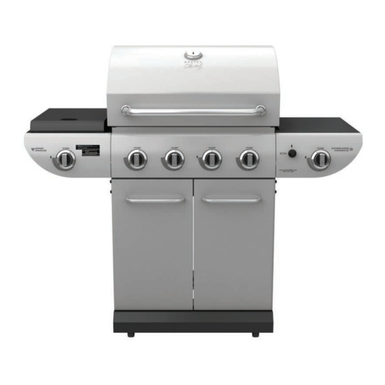
E500 Barbecue
Assembly Manual
85-3044-6 (G45308) Propane
85-3045-4 (G45309) Natural Gas
1 YEAR LIMITED WARRANTY
READ AND SAVE MANUAL FOR FUTURE REFERENCE.
If pre-assembled, leave this manual with unit for
consumer's future reference.
For product inquiries, parts, warranty and
troubleshooting support, please call 1-877-707-5463.
Manual Revision #: 27092012 MD
ANS Z21.58b-2012-CSA 1.6b-2012
ANS Z21.58b-2012-CSA 1.6b-2012
ANS Z21.58b-2012-CSA 1.6b-2012
Advertisement

Related Manuals for Master Chef E500


Summary of Contents for Master Chef E500
- Page 1 E500 Barbecue Assembly Manual 85-3044-6 (G45308) Propane 85-3045-4 (G45309) Natural Gas 1 YEAR LIMITED WARRANTY READ AND SAVE MANUAL FOR FUTURE REFERENCE. If pre-assembled, leave this manual with unit for consumer’s future reference. For product inquiries, parts, warranty and troubleshooting support, please call 1-877-707-5463.
-
Page 2: Hardware Pack
HARDWARE PACK TOOLS NEEDED FOR ASSEMBLY KEY # DESCRIPTION PART NUMBER QUANTITY ¼”-20UNCX38 Screw 20120-13038-250 ¼”-20UNCX18 Screw 20120-13018-250 • #2 Phillips screwdriver (long and short) ¼”-20UNCX13 Screw 20120-13013-250 • ¼” Slotted screwdriver (long and short) ¼” Nut 30220-13000-250 φ7 Lock Washer 41400-07000-250 •... - Page 3 PARTS LIST (PROPANE) FOR 85-3044-6 (G45308) EXPLODED DIAGRAM (PROPANE) FOR 85-3044-6 (G45308) KEY # QUANTITY DESCRIPTION PART NO. Top lid G453-5100-01 Lid handle G513-0004-01 Thermometer G432-R200-01 Screw for top lid G453-0025-01 Lid bumper, front G508-0063-01 Lid bumper, rear G508-0033-01 Burner box weldment G453-2200-01 Flame tamer brace G453-0004-01...
- Page 4 PARTS LIST (NATURAL GAS) FOR 85-3045-4 (G45309) EXPLODED DIAGRAM (NATURAL GAS) FOR 85-3045-4 (G45309) KEY # QUANTITY DESCRIPTION PART NO. Top lid G453-5100-01 Lid handle G513-0004-01 Thermometer G432-R200-01 Screw for top lid G453-0025-01 Lid bumper, front G508-0063-01 Lid bumper, rear G508-0033-01 Burner box weldment G453-2200-01...
-
Page 5: Assembly Instructions
ASSEMBLY INSTRUCTIONS ASSEMBLY INSTRUCTIONS THIS STEP REQUIRES 3 PEOPLE. DO NOT Separate the 2 different types of castors: 2 Locking Castors (EE) and 2 Regular Castors (EF). ATTEMPT ALONE. EXTREMELY HEAVY! Note: Regular Castors (EF) need to be Position the Top Lid Assembly and Burner Box assembled to the front of the Bottom Shelf Assembly (A &... - Page 6 ASSEMBLY INSTRUCTIONS ASSEMBLY INSTRUCTIONS Attach the Match Holder (BI) to the left side panel Assemble the Door Support Rail (EA) to the Left of the Burner Box Assembly. and Right Upper Side Panels (EB and EC), as shown. YOU WILL NEED: WARNING: This part may have sharp edges.
- Page 7 ASSEMBLY INSTRUCTIONS ASSEMBLY INSTRUCTIONS LEFT SIDE SHELF ASSEMBLY a. Remove the hardware that is pre-assembled to the IR side burner valve (CC), as shown in a. Mount the left side burner side shelf (DA and figure A. DB) onto the two support brackets, located Insert the side burner valve stem (CC) through on the left, upper side panel of the burner box the rear of the left side shelf fascia (DB) and...
- Page 8 ASSEMBLY INSTRUCTIONS ASSEMBLY INSTRUCTIONS a. Assemble the venturi wind shield (DL) to the e. Feed the infrared electrode (DE) from infrared support frame (DC). underneath the infrared side burner (DD), through the small opening on the right side of the infrared support frame (DC). Align and assemble the electrode using the self tapping YOU WILL NEED: screw provided, as shown in figure E.
- Page 9 ASSEMBLY INSTRUCTIONS ASSEMBLY INSTRUCTIONS ELECTRONIC IGNITION ASSEMBLY RIGHT SIDE SHELF ASSEMBLY TIP: Do not tighten until all hardware is in place. Battery a. Remove the electronic ignition button (CH2) and the plastic nut from the Electronic Igniter a. Mount the right side shelf (DH and DI ) onto Assembly (CH1) the two support brackets, located on the right, upper side panel of the burner box (BA).
- Page 10 ASSEMBLY INSTRUCTIONS ASSEMBLY INSTRUCTIONS a. Remove the hardware that is pre-assembled to the Rotisserie Burner Valve (BN), as shown in figure A Assemble the Rotisserie Burner Valve (BN) to the Right Side Shelf Fascia (DI), using the hardware removed. b. Assemble the Side Burner Control Knob (#18) to the Rotisserie Burner Valve (BN).
- Page 11 ASSEMBLY INSTRUCTIONS ASSEMBLY INSTRUCTIONS a. Assemble the right door assembly (EH), to the bottom shelf (ED) by inserting the fixed pin (bottom of door) into the hole provided (figure B). Close up, front b. Insert the Grease Tray (CL) into the opening of the Upper Back Panel (BH).
- Page 12 ASSEMBLY INSTRUCTIONS ASSEMBLY INSTRUCTIONS a. Position the Flame Tamer support braces Place the cooking grates (BF) into the burner box (BB) over the Burner Box support pins (BA) as (BA). shown. b. Position the Flame Tamers (BE) into the Burner Box (BA).
- Page 13 LP cylinder valve. ATTENTION FOR YOUR SAFETY, DO NOT ATTEMPT TO LIGHT THIS BBQ UNTIL YOU HAVE REVIEWED PAGES 4-8 OF THE MASTER CHEF® SAFETY & CARE MANUAL. ALL SAFETY AND LEAK TESTS MUST BE PERFORMED BY THE END USER, PRIOR TO LIGHTING THIS BBQ.
Need help?
Do you have a question about the E500 and is the answer not in the manual?
Questions and answers