Table of Contents
Advertisement
Quick Links
Advertisement
Table of Contents

Related Manuals for Perle MCR1900


Summary of Contents for Perle MCR1900
-
Page 1: Media Converter
MCR1900 Media Converter 19-Slot Chassis Installation Guide Part #5500304-11... - Page 2 Markham, ON Canada L3R 0E1 Perle reserves the right to make changes without further notice, to any products to improve reliability, function, or design. Perle, the Perle logo, and MCR1900 are trademarks of Perle Systems Limited. Perle Systems Limited, 2011.
-
Page 3: Table Of Contents
Table of Contents Preface .................5 Chapter 1 Overview.............7 Getting to Know the MCR1900............ 7 Front and Rear Panel Components..........8 Front View (with Media Converter Modules installed) ......8 Rear View (one AC and one DC Power Supply Modules installed) ..8 Power Supply Module.............. - Page 4 Table of Contents Chapter 3 Media Converter Modules .......20 Installing or Replacing Media Converter Modules ....20 Removing Media Converter Modules............ 20 Installing or Replacing Media Converter Modules....... 20 Chapter 4 Power Supply Modules ........22 Installing or Replacing the Power Supply Module ....22 Removing the Power Supply Module............
-
Page 5: Preface
The installation and user guides (in PDF format) for all Perle products can be found at http://www.perle.com/downloads Warranty / Registration Perle’s standard Lifetime Warranty provides customers with the return to factory repairs for Perle products that fail under the conditions of the... -
Page 6: Technical Support
Product Information For more product details and information about Perle products use the link below. http://www.perle.com/products Chat Live To chat live with a Perle Sales Representative use the link below. http://www.perle.com/chat.shtml Address Perle Systems Limited. 60 Renfrew Drive Markham, Ontario... -
Page 7: Chapter 1 Overview
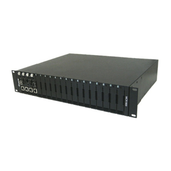
Overview Chapter 1 Getting to Know the MCR1900 The MCR1900 is used to aggregate large numbers of geographically separated Ethernet, Fast Ethernet and Gigabit Ethernet networks into a central location, over fiber optic cables. The MCR1900 Chassis features include: Nineteen slots for Media Converter Modules. -
Page 8: Front And Rear Panel Components
Power Supply Module The MCR9100 Chassis has two Bays for Power Supply Modules located at the rear of the Chassis. The MCR1900 Chassis can support two AC or two DC power supplies or a combination of either. Each Power Supply Module has a cooling fan that draws air out of the Chassis through front air vents on all face plates. - Page 9 Modules power requirements can be met with one Power Supply, however a second Power Supply can be added for power redundancy and load-sharing. If the Chassis has two Power Supply Modules, the modules will use a load-sharing arrangement in which they both supply power to the Media Converter Modules and Chassis.
-
Page 10: Power Supply Led Status
Intelligent Alarm Relay The Perle MCR1900 Chassis is fashioned with an Intelligent Alarm Relay. This relay is engaged after the unit is powered up and the backplane has been initialized. Should a failure occur, the relay will... - Page 11 be disengaged, therefore setting the alarm until the unit returns to a normal state of operation. A failure can be one of the following: Loss of power to the Power Supply Module(s). Fan failure. Over temperature heat protection. Over voltage protection. The relay is accessible via a set of three contact connections.
-
Page 12: Media Converter Modules
Media Converter Modules For information regarding Media Converter Installation, see the appropriate Installation Guide for that product. -
Page 13: Chapter 2 Installing The Mcr1900
Installing the MCR1900 Chapter 2 Unpacking the MCR1900 Chassis Item MCR1900-19-Slot Chassis with one or two AC/DC Power Supplies country specific power cord 19-inch rack mount kit MCR1900 Media Converter 19-Slot Chassis Installation Guide (this guide) Available Accessories The following accessories can be ordered separately:... -
Page 14: Power Requirements
The following are the ranges for the DC voltage supported by the unit; Minimum: 24 VDC Nominal: 48 VDC Maximum: 60 VDC You need wire gauge 14 to 18 AWG to connect the MCR1900 chassis to the power source. -
Page 15: Grounding The Mcr1900 Chassis
For dual power supply models, ensure both sources have been disconnected. Grounding the MCR1900 Chassis The MCR1900 should always be chassis grounded for safe and proper operation. Grounding the Chassis requires the following items: One grounding lug (not provided). -
Page 16: Installing The Media Converter Modules
Connecting the Alarm Relays (optional) The MCR1900 provides a method of allowing you to connect an external powered device such as a siren or light in order to inform you should a power loss or failure occur. The Common relay connection is used in conjunction with the Normally Closed or Normally Open terminals. -
Page 17: Powering On An Ac Powered Chassis
To power on an AC powered Chassis, perform the following procedure. Using the Perle supplied power cord, plug the power cord into the AC power connector at the rear of the Chassis (repeat this procedure if you have a second power supply installed in the Chassis). - Page 18 Power Supply LED Status Description On (solid) Indicates that the power has been switched On and the Power Supply Module is supplying power to the Chassis. The Power Supply Module has been switched Off. The power plug has been removed. No power at power source.
- Page 19 Warning For your safety, before attempting to connect or modify any of the electrical connections to the unit, please be sure all wiring is disconnected from any live power source. Power should only be applied when you are sure that the wiring is correct and any safety covers are properly installed.
-
Page 20: Chapter 3 Media Converter Modules
Chassis. Failure to observe this precaution could result in damage to the Media Converter Module. The Perle Media Converter Modules may be installed in any order and in any available installation slot. All Perle Media Converter Modules are hot-swappable and can be removed or installed while the Chassis is powered on. - Page 21 as you might damage the module. If there is resistance, remove the module and check the module’s backplane connector for damage to the pins. If the module’s backplane conector is not damaged, retry the insertion. Captive screws Captive retainer screw Tighten the Captive retainer screw to ensure the Media Converter Module is locked in place.
-
Page 22: Chapter 4 Power Supply Modules
Use these procedures for AC or DC power supply modules. The MCR1900 Power Supply Module is hot-swappable and can be removed or installed while the Chassis is powered on. The MCR1900 comes with two Power Supply Bays with one or two Power Supply Module(s) installed. -
Page 23: Installing Or Replacing The Power Supply Module
Power Supply Module. Tighten the Captive retainer screws on either side of the Power Supply Module. Connect the power cord to the MCR1900 Power Supply Module. Connect the power cord its source. If this is a DC Power Supply see section "Powering On an DC... - Page 24 Turn the power switch to the On position. Warning If the Intelligent Alarm Relay has been connected to an audible or visual alarm, the insertion of a second Power Supply Module will engage the alarms until the power switch has been set to the On position.
-
Page 25: Appendix A Technical Specifications
Technical Specifications Appendix A Environmental Specifications Operating Temperature 0 C to 50 C (32 F to 122 Storage Temperature C to 70 F to 150 O p e r a t i n g / S t o r a g e 5% to 95% (non condensing). -
Page 26: Ac Power Specifications
AC Power Specifications Nominal Input 100/240 V AC Voltage Input Voltage range 90 to 264 V AC AC Input Frequency 50 to 60 Hz Capacity DC Power Specifications Minimum Input 24 VDC Nominal Input 48 VDC Maximum Input 60 VDC Capacity... -
Page 27: Appendix B Troubleshooting
Troubleshooting Appendix B This chapter provides information that can help resolve issues with your Perle MCR1900 Chassis. Intelligent Alarm Relay The relay can be engaged for any of the following conditions. Condition Possible Cause Loss of Power Loss of power source to the Power Supply Module. -
Page 28: Power Supply Led Status
Power Supply LED Status Description On (solid) Indicates that the power has been switched On and the Power Supply Module is supplying power to the Chassis. The Power Supply Module has been switched Off. The power plug has been removed. No power at power source.
Need help?
Do you have a question about the MCR1900 and is the answer not in the manual?
Questions and answers