
Subscribe to Our Youtube Channel
Related Manuals for Perle MCR1900


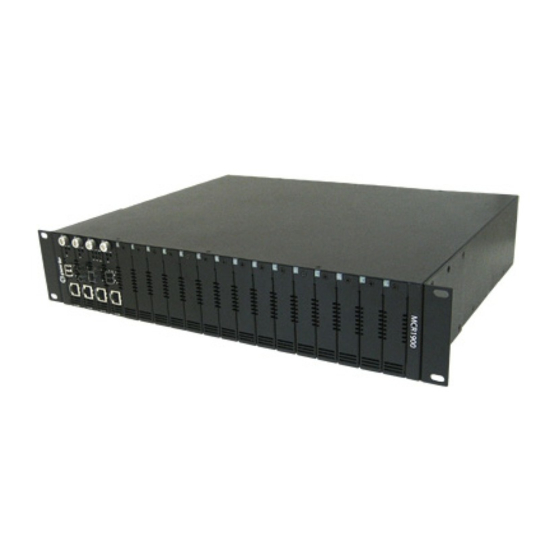
Summary of Contents for Perle MCR1900
- Page 1 MCR-MGT Management Module User’s Guide January 2017 Version A.1.17.01.2017 Part #5500310-16 MCR-MGT Management Module, User’s Guide...
- Page 2 Canada L3R 0E1 Perle reserves the right to make changes without further notice, to any products to improve reliability, function, or design. Perle, the Perle logo are trademarks of Perle Systems Limited. Microsoft and Internet Explorer are trademarks of Microsoft Corporation.
-
Page 3: Table Of Contents
General Features................5 Management Features ..............5 Control Features ................6 Security Features................. 6 Additional Features for the MCR1900 ........6 Additional Features on some media modules ......6 Chapter 2 Setting IP Addresses.........8 SetIP Utility ................... 8 Using CLI commands ..............9 Chapter 3 Configuration Methods ........11... - Page 4 Configuration ..................19 Backplane ..................19 Media Converter Modules ..............19 MCR1900 Chassis View ................. 20 Populating Slots In the MCR1900 Chassis........... 20 Unmanaged modules ................. 20 Empty slot ..................21 Chapter 5 SMI Media Converter ........22 SMI Media Converter ................22...
- Page 5 Port Setup Tab ..................25 Serial ....................25 Ethernet....................26 Advanced Tab ..................27 Management Module View ............28 MCR1900 Chassis................... 28 Power Schedule ................. 29 Network ....................30 Advanced ................... 34 Access ..................... 43 MCR Web Manager ................44 SSH....................
- Page 6 Table of Contents Display Formats..................71 Files ......................71 Firmware .................... 71 MCR 1900 Media Converter Module Firmware Update ..... 73 Manual Update................... 73 Automatic Update................74 SMI Media Converter Firmware Update..........74 Manual Update................... 74 Automatic Update................75 Configuration..................75 Keys and Certificates .................
- Page 7 Advanced Tab ..................126 Chapter 11 CM-100MM Media Converter Module ..128 CM-100MM Media Converter Module Parameters....128 General Tab................... 128 MCR1900 Chassis ................128 SMI Chassis ..................128 Fiber Port 1 Tab ..................131 Fiber Port 2 Tab ..................132 Alert Log Tab ..................
- Page 8 Table of Contents Advanced Tab ..................139 Chapter 13 CM-10G Media Converter Modules ....141 Standard Models................... 141 High Power Models ................141 CM-10G Modules Parameters ..........142 General Tab................... 143 Port 1 Tab ....................145 Port 2 Tab ....................146 Alert Log Tab ..................
- Page 9 Table of Contents Slot......................177 Chapter 16 CM-4GPT-DSFP Media Converter Module .179 CM-4GPT-DSFP Media Module Parameters......179 General Tab................... 180 Port 1 ..................... 182 Port 1 SFP ..................... 183 Port 2 ..................... 183 Port 2 SFP ..................... 184 Alert Log....................184 Advanced Tab ..................
- Page 10 Table of Contents Communication Issues............207 Host Problems................207 RADIUS Authentication Problems.......... 207 Unknown IP Address ............... 208 SSL/TLS ..................208 IPv6 Issues ................208 Contacting Technical Support..........209 Appendix F Symmetric Key File........210 Symmetric Key File..............210...
-
Page 11: Preface
MCR-MGT Management Module. Contents of CD The following documentation is included on the MCR-MGT Management Module Installation CD: MCR1900 Media Converter 19-Slot Chassis Installation Guide SMI Media Converter Installation Guide MCR-MGT Management Module User’s Guide ... -
Page 12: Typeface Conventions
Typeface Conventions Typeface Conventions Most text is presented in the typeface used in this paragraph. Other typefaces are used to help you identify certain types of information. The other typefaces are: Typeface Example Usage At the C: prompt, type: This typeface is used for code examples and system- generated output. -
Page 13: Chapter 1 Introduction
Introduction Chapter 1 About the MCR-MGT Management Module The following software features are available on the MCR-MGT module. Accessing the MCR-MGT Management Module The MCR-MGT Management Module can be accessed through any of the following methods: MCR Web Manager, a (http/https) web browser ... -
Page 14: Control Features
SSL/TLS v1.1 and v1.2 connections. Filter network services Local event log with filtering per module basis Additional Features for the MCR1900 Chassis temperature, voltage and fan monitoring ECO power scheduler feature allows you to set power on/off schedules ... - Page 15 Additional Features on some media modules Insert double tag Other Unidirectional Ethernet Filtering of unknown multicast frames Filtering of unknown unicast frames...
-
Page 16: Chapter 2 Setting Ip Addresses
The easiest method to assign an IP address to your MCR-MGT Management Module is to use the Perle SetIP Utility. The Perle SetIP Utility will allow you to assign an IP address and/or manage a predefined Management Module. This utility can be found on the Perle CD that came with your Management Module. -
Page 17: Using Cli Commands
You can connect to the Management’s Module’s serial console port using a PC with a terminal emulation package, such as HyperTerminal or a terminal. Using an RJ-45 patch cable and a CISCO RJ45-DB9F-DTE Pinout adapter (Perle part number 04007040), connect your PC or dumb terminal to the console port on the Management Module. - Page 18 Using CLI commands Confirm reboot unit y/n Type Connecting to the Management Module’s Internal IPv6 address The Management Module has a link local IPv6 address based upon its MAC Address. For example, the link local address is: Management Module MAC Address: 00-80-D4-AB-CD-EF Link Local Address: FE80:0280:D4FF:FEAB:CDEF Using Telnet or SSH you can connect to the Management Module’s IPv6 local link address and configure the Management Module.
-
Page 19: Chapter 3 Configuration Methods
Configuration Methods Chapter 3 Introduction This chapter provides information about the different methods you can use to configure the MCR- MGT Management Module (Management Module). Before you can configure the Management Module, you must assign an IP address. See Chapter 2, Setting IP Addresses to find out how to assign an IP address to the Management Module. - Page 20 Enter. http://10.0.0.10 or https://10.0.0.10 If you successfully connect to the Management Module, either a MCR1900 screen or a SMI Media Converter screen will appear. MCR1900 The top portion of the screen (chassis view) will display the chassis and all modules detected. This will include;...
- Page 21 MCR Web Manager SMI Media Converter The top portion of the screen will display the installed MCR-MGT module and the detected media converter module. If any module has an active alarm (severity level “System Level Fault”, “Module level Fault” or “Persistent Error”), a red triangle will show up on that module.
-
Page 22: Using Webmanager
MCR Web Manager Using WebManager Click the MCR-MGT Management Module. MCR-MGT Management Module MCR-MGT Management Module You navigate through the different configuration windows by selecting a navigation tab. Each of the navigation tabs open to more options and windows. Administration Button Navigation Tabs Configuration Methods 14... -
Page 23: Command Line Interface
Command Line Interface The Administration button will take you to the navigation Tree as shown below. Navigation Tree Navigation Tree Note: Remember to click on the Apply button to save your configuration changes. Command Line Interface Overview The Command Line Interface (CLI) is a command line option configuration for the Management Module. -
Page 24: Menu
Menu Menu Overview The Menu is a graphical representation of the CLI. You can look up Menu parameter explanations in the Command Line Interface Reference Guide. The only operations that the Menu does not support are the downloading or uploading of files to/from the Management Module. Access Platforms The Menu is accessed by any application that supports a Telnet or SSH session to the Management Module’s IP address, such as Putty, SecureCRT, or from a command prompt. -
Page 25: Snmp
Community=public, Permissions=Readonly Community=private, Permissions=Readwrite Accessing MCR-MGT using SNMP Load the MCR-MGT.MIB file from the Perle Management Module CD-ROM or Perle website into your SNMP manager. Type in the IP address of the Management Module. You are now ready to start configuring and managing your Management Module and Media Converter Modules using SNMP. -
Page 26: Chapter 4 Mcr1900 Chassis
(or locally) connect to the chassis and monitor or control any of its functions. All event notification will be lost as well as any scheduled slot power up/down functionality. Firmware Components The MCR1900 chassis has a number of intelligent components, each with supporting firmware. These components are; ... -
Page 27: Configuration
Management Module itself) can be upgraded. The firmware residing on Managed Media Converter Modules can be updated manually (user intervention required) or automatically to the latest firmware versions. The Management Module and Media Converter Modules can be at different firmware versions. The power supply and backplane firmware is embedded in the Management Module image and is updated automatically by the management card so that they always match its firmware. -
Page 28: Mcr1900 Chassis View
MCR1900 Chassis View The Chassis section is used to view the parameters directly associated with the MCR1900 chassis. General Model The Model of the chassis. The current temperature of the chassis. Current Temperature When the temperature of the chassis exceeds this threshold, alerts will be Maximum generated. -
Page 29: Empty Slot
Empty slot If a slot is empty the management card can perform the following actions on this slot; Power the slot on or off Define a default power state for this slot Disable the “Backup/Restore Module Configuration Automatically” option. ... -
Page 30: Chapter 5 Smi Media Converter
SMI Media Converter Chapter 5 General information on the SMI Media Converter SMI Media Converter This chassis consists of 2 slots. One Management Module plus 1 Media Converter Module are supported. By default, slot 1 of the SMI Media Converter will be populated with a MCR-MGT management module and slot 2 will be populated with a Media Converter module. -
Page 31: Chassis
configuration. If there is no configuration in flash, the Media Converter Module will read the settings of the DIP switches and use those as its running configuration. When configuring the Media Converter Module, you may enable the “Backup/restore Module Configuration Automatically”. When this option is used, the Media Converter configuration is also stored on the Management Module. -
Page 32: Chapter 6 Mcr-Mgt Module
MCR-MGT Module Chapter 6 MCR-MGT Management Module The MCR Web Manager screens will be used to explain the various parameters associated with each component of the system. The parameters have the same meaning in all configuration tools. General Tab Field Descriptions Displays the module’s model information. -
Page 33: Port Setup Tab
MCR-MGT Management Module Field Descriptions Configure the following parameters: Shows Alerts for the Entire System, Chassis or a specific slot. Show Alerts Clears the Alert Log for the Entire System. Clear Alerts Port Setup Tab Serial The serial console port is used to obtain local access to the MCR-MGT module. The port allows the user to configure, monitor and/or control the system modules via CLI (Command Line Interface) or Menu (a series of menus). -
Page 34: Ethernet
MCR-MGT Management Module Field Descriptions Enable Serial Enables/Disables the serial console port. Console Default: Enabled Speed Specifies the baud rate of the serial console port. Data Options: 9600, 19200, 38400, 57600 or 115200 Default: 9600 Parity Specifies the type of parity being used for the data communication on the serial port. -
Page 35: Advanced Tab
MCR-MGT Management Module Field Descriptions Speed and Duplex Define the Ethernet connection. Data Options: Auto —automatically detects the Ethernet interface speed and duplex 10 Mbps/Half Duplex 10 Mbps/Full Duplex 100 Mbps/Half Duplex 100 Mbps/Full Duplex ... -
Page 36: Management Module View
To get back to the “Chassis” view, click on the “Chassis View” item on the top of the navigation tree. This will return you to the screen with the graphical representation of the chassis. MCR1900 Chassis The Chassis section is used to configure the parameters directly associated with the chassis. -
Page 37: Power Schedule
The parameters in Power Scheduler allow you to configure each slot within the Chassis to be automatically turned On or Off according to a user pre-defined schedule. This feature is available on the MCR1900 chassis only. Schedule Field Descriptions Clicking on “Change” for a specific slot above, you will be presented with the following screen;... -
Page 38: Network
Management Module View Network The Network node allows you to set up your IPv4 or IPv6 network permeates to be used on the Ethernet port of the MCR-MGT Management Module. These are used by the Management Module to access the network. Configure the following parameters: System Name is used for informational purposes by such tools as the... - Page 39 Management Module View IP Address The IPv4 network address you wish to assign to the MCR-MGT management module’s Ethernet port. For example: 172.16.113.79 Subnet Mask The IPv4 subnet mask you wish to assign to the MCR-MGT management module’s Ethernet port. For example, 255.255.0.0 Default Gateway Specify the gateway IP address that will provide general access beyond the local network.
- Page 40 Management Module View IPv6 When enabled, the MCR-MGT Management Module will send out a Router Autoconfiguration Solicitation message. If a Router Advertisement message is received, the MCR- MGT Management Module will configure the IPv6 address and configuration parameters based on the information contained in the advertisement. If no Router Advertisement message is received, the MCR-MGT Management Module will attempt to connect to a DHCPv6 server to obtain IPv6 addresses and other configuration parameters.
- Page 41 Management Module View Configure the following parameters: Create a unique When enabled, the MCR-MGT Management Module will derive an IPv6 IPv6 address on the address from the entered network prefix and the MCR-MGT Management network Module’s MAC address. Default: Enabled Network Prefix Specify the IPv6 network prefix.
-
Page 42: Advanced
Management Module View Advanced Advanced node configures Host Table entries, Routes, DNS, Dynamic DNS and IPv6 Tunnels. Configure the parameters in the Advanced node if you want to add a specific host modify the host table add a route to an external network or host ... - Page 43 Management Module View Adding/Editing a Host Configure the appropriate parameters. Host Name The name of the host. This is used only for the MCR-MGT Management Module configuration. Field Format: Up to 14 characters, no spaces. IP Address The IP address of the Host you want to add. Field Format: IPv4 or IPv6 address You can configure up to four DNS servers.
- Page 44 Management Module View Field Descriptions The following buttons are available on this window: Add Button Adds a route to the Route List. Edit Button Changes an existing route in the Route List. Delete Button Deletes a route from the Route List. Adding/Editing Routes From the tab, if you click the...
- Page 45 Management Module View IP Address When the route is defined as , this field will contain the IP address of Type Host the host. If the route is defined as , the network portion of the IP Type Network address must be specified and the Host port of the address will be set to 0. Example: to access network 10.10.20, the address 10.10.20.0 would be specified in this field.
- Page 46 Management Module View Editing/Adding DNS Servers Configure the parameter: You can configure up to four DNS servers. DNS IP Address Field Format: IPv4 or IPv6 address Dynamic DNS Dynamic DNS Service providers enable users to access a server connected to the internet that has been assigned a dynamic IP address.
- Page 47 Management Module View Enable Dynamic Enables/disables the dynamic DNS feature. When Dynamic DNS is enabled, DNS for the system the MCR-MGT Management Module will automatically update its IP address with DynDNS.org if it changes. Default: Disabled Service Provider Displays the Dynamic DNS service provider. Default: DynDNS.org (permanent) Register Host Name Specify the registered hostname with DynDNS.org that will be updated with the MCR-MGT Management Module’s IP address should it change.
- Page 48 Management Module View Validate Peer Enables/disables peer validation between the DynDNS.org server and the Certificate MCR-MGT Management Module. This may be desirable, since the DynDNS user name and password are sent from the management module to the DynDNS server when the IP address needs to be updated and when an account refresh is performed.
- Page 49 Management Module View Configure the following parameters: Encryption Select the type of encryption that will be used for the SSL connection. Data Options: Any—Will use the first encryption format that can be negotiated. AES-CBC 3DES Cast ...
- Page 50 Management Module View Validation Criteria Field Descriptions If you choose to configure validation criteria, the information in the peer SSL/TLS certificate must match exactly the information configured in this window in order to pass peer authentication and create a valid SSL/TLS connection. IPv6 Tunnels IPv6 tunnels transport IPv6 data packets from one IPv6 network to another IPv6 network over an IPv4 network.
-
Page 51: Access
Management Module View Adding/Editing an IPv6 Tunnel When you add/edit an IPv6 tunnel, you are determining how an IPv6 message will reach an IPv6 device through an IPv4 network. Configure the following parameters: Name The name of the IPv6 tunnel. Field Format: Maximum 16 alphanumeric characters Default: ipv6_tunnel1 Mode... -
Page 52: Mcr Web Manager
Management Module View Unchecking the box next to each of the services listed above, will disable this service and users will no longer be able to reach the MCR-MGT module using that service. The session inactivity timer is only used when “Bypass login” is not enabled (i.e. login is required). If no activity is detected on the session for the amount of time configured here, the session will be terminated. - Page 53 Management Module View Functionality When you are using the SSH connection protocol, keys need to be distributed to all users and the Management Module. Below is an example scenario for key/certificate distribution. Users Logging into the Management Module Using SSH In the following example, users are connecting to the Management Module via SSH from the LAN.
-
Page 54: Snmp
Management Module View Password The user types in a password for authentication. Default: Enabled 3DES The Management Module SSH server’s 3DES encryption is enabled/disabled. Default: Enabled CAST The Management Module SSH server’s CAST encryption is enabled/disabled. Default: Enabled Blowfish The Management Module SSH server’s Blowfish encryption is enabled/disabled. - Page 55 Management Module View Field Descriptions Configure the following parameters. Contact The name and contract information of the person who manages this SMNP node. Location The physical location of the SNMP node. Community The name of the group that devices and management stations running SNMP belong to.
-
Page 56: Authorized Hosts
Management Module View Security Level Select the security level for the user. This must match the configuration set up in the SNMP manager. Data Options: None—No security is used. Auth—User authentication is used. Auth/Priv—User authentication and privacy (encryption) settings are used. -
Page 57: Authentication And Accounting
Management Module View Field Descriptions Data Options: System Access Policy Allow all network hosts— Allows any host to connect to the MCR-MGT Management Module. Only allow authorized hosts—A security feature that when enabled, the Management Module will only accept data from or send data to hosts configured in this table, Host Table, DNS Servers, SNMP communities, SNMP Traps, LDAP authentication Host IP server address, Email server Host IP address and Bootup files Host IP address. - Page 58 Management Module View Field Descriptions Configure the following parameters. Bypass login When “Bypass login” is selected (enabled), a user accessing the MCR-MGT module is not asked to login. Default: Enabled When "Require Login" is selected (enabled), a user accessing the MCR-MGT Require Login module is presented with a login prompt or screen before they can obtain access to the management module.
-
Page 59: Local
Management Module View Specific authentication methods Local When Local authentication is selected, the user must be configured in the Management Module’s list. A maximum of 31 users can be configured in the list. User Accounts Field Descriptions Configure the following parameters: The name of the user. -
Page 60: Radius
Management Module View RADIUS When setting up users on the Radius host, you can specify the permission level this user will have on the MCR-MGT Management Module (i.e. admin or operator). To do this, you need to set the radius parameter “Service_Type”... - Page 61 Management Module View First Accounting Name of the primary RADIUS accounting host. Host Default: None Second Accounting Name of the secondary RADIUS accounting host. Host Default: None Accounting Port The port that the RADIUS host listens to for accounting requests. Default: 1813 Change Secret The secret (password) shared between the Management Module and the...
-
Page 62: Kerberos
Management Module View Use the following When enabled, the Management Module will send the specified IPv4 address NAS-IP-Address to the RADIUS server. Default: Disabled IP Address The IPv4 address that the Management Module will send to the RADIUS server. Default: 0.0.0.0 Automatically When enabled, the Management Module will send the Management Module’s determine NAS-... -
Page 63: Ldap/Microsoft Active Directory
Management Module View LDAP/Microsoft Active Directory LDAP (Lightweight Directory Access Protocol) is an application protocol for querying and modifying directory services running over TCP/IP. It is also used as a method of authenticating users. Microsoft Active Directory is an LDAP like directory service. It can be used for authenticating users in a similar fashion to LDAP. - Page 64 Management Module View Encrypt Passwords Checking this parameter will cause the Management Module to encrypt the Using MD5 digest password using MD5 digest before sending it to server. If this option is not checked, the password is sent to the server in the clear. Default: Disabled Authenticate with This option will cause the Management Module to authenticate with the LDAP...
-
Page 65: Tacacs
Management Module View TACACS+ Field Descriptions Configure the following parameter. Authentication/ The primary TACACS+ host that is used for authentication. Authorization Default: None Primary Host Authentication/ The secondary TACACS+ host that is used for authentication, should the Authorization primary TACACS+ host fail to respond. Secondary Host Default: None Authentication/... - Page 66 Management Module View Accounting Port The port number that TACACS+ listens to for accounting requests. Default: 49 Accounting Secret The TACACS+ shared secret is used to encrypt/decrypt TACACS+ packets in communications between two devices. The shared secret may be any alphanumeric string up to 30 characters.
-
Page 67: Securid
Management Module View SecurID If you need to reset the SecurID secret, select Administration, Authentication, Securid, Settings Reset SecurID Node Secret Field Descriptions Configure the following parameters. Primary/Master The first SecurID server that is tried for user authentication. Host Default: None Replica/Slave Host If the first SecurID server does not respond to an authentication request, this is the next SecurID server that is tried for user authentication. -
Page 68: Nis
Management Module View Field Descriptions Configure the following parameters. NIS Domain The NIS domain name. Primary NIS Host The primary NIS host that is used for authentication. Default: None Secondary NIS Host The secondary NIS host that is used for authentication, should the primary NIS host fail to respond. -
Page 69: Alerts
Management Module View Alerts The MCR-MGT Management Module supports the ability to provide notification of important events occurring in the system. The events can be communicated via one or more of the following methods; Local Event Log Email ... -
Page 70: Local Event Log
Management Module View Local Event Log The MCR-MGT Management Module has a built-in local event log. The event log is a circular buffer that can hold up to 200 local event messages. Once the log is full, the oldest entries will be replaced with new entries. -
Page 71: Email Alerts
Management Module View Email Alerts Email notification requires an SMTP host that is accessible by the Management Module to process the email messages sent by the Management Module. Field Descriptions Configure the following parameters: Send Email Alert Enables/disables Email Alerts. Default: Disabled Email Alert Level Choose the alert level that will trigger a notification to be sent to the local log. - Page 72 Management Module View Password Enter the password associated with the user configured in “Username”. Maximum size of password is 64 characters. Encryption Choose the type of encryption desired. Valid options are; None - All information is sent in the clear. ...
-
Page 73: Syslog
Management Module View Syslog The Management Module can be configured to send system log messages to a syslog daemon running on a remote host if the Syslog service is activated. You can configure a primary and secondary host for the syslog information and specify the level for which you want syslog information sent. -
Page 74: Snmp Traps
Management Module View SNMP Traps If MCR-MGT Management Module supports the use of SNMP traps to communicate significant events to an SNMP trap host. Up to 4 trap hosts can be defined to receive the traps. Each host can be configured independently for the version of traps that it supports. - Page 75 Management Module View SNMP Version Defines the SNMP version of the traps sent to the specified host. If v3 is selected then the SNMP trap v3 user will be used to authenticate the trap with the specified host. Valid options are v1, v2c or v3. Default: v1 This field is ignored for trap host version v1"...
-
Page 76: Date And Time
Management Module View Confirm Password Retype the privacy password. This is only used for "Inform" traps. Select the number of seconds to wait for Inform Retires the acknowledgement of the trap. Default: 1 second This is only used for "Inform" traps. Select the number of times the trap will Inform Retries be sent if no acknowledgement is received. - Page 77 Management Module View Field Descriptions Configure the following parameters: Time Zone Name The name of the time zone to be displayed during standard time. Field Format: Maximum 4 characters and minimum 3 characters (do not use angled brackets < >) Time Zone Offset The offset from UTC for your local time zone.
- Page 78 Management Module View Recurring Start Sets the relative date and time in which the Management Module’s clock will Date change to summer time (daylight saving time) hours. Sunday is considered the first day of the week. Recurring End Date Sets the relative date and time in which the Management Module’s clock will end summer time hours and change to standard time.
-
Page 79: Display Formats
Management Module View Secondary Host The name of the secondary SNTP server from the Management Module host table. Valid with modes, although in mode, Unicast Multicast Multicast the Management Module will only accept broadcasts from the specified host SNTP server. Key ID Specify the key id associated with this host. - Page 80 TFTP server set up with the firmware files residing on it. With HTTP, you can use the same PC as the one which your browser is running on without the need for any additional software. You must agree to the Perle Licensing Agreement and the Privacy Policy in order to download firmware.
-
Page 81: Mcr 1900 Media Converter Module Firmware Update
Management Module View After the download has completed, a status dialog will appear. MCR 1900 Media Converter Module Firmware Update Manual Update Manually update one or more managed Media Converter Modules of the same type. From the drop down box, select the Module Type. Displayed is a list of slots which contain this Module Type. -
Page 82: Automatic Update
Management Module View Automatic Update Automatically update managed Media Converter Modules. Only media converter modules that are running older versions of the firmware will be updated. The Media Converter Module firmware bundle is included with management module firmware. Automatic updates will occur when the: ... -
Page 83: Automatic Update
Management Module View Automatic Update The Media Converter Module firmware bundle is included with management module firmware. Automatic updates will occur when the: Management Module is restarted Chassis is power cycled Managed Media Converter Module is inserted Note: Remember to click the Apply button to save your configuration changes. -
Page 84: Diagnostic File
Diagnostic File Should the Management Module experience any problems, a Perle Technical support representative may ask you to get this file and sent it to us. Uploading this file will permanently remove it from the non-volatile memory on the MCR-MGT Management Module. -
Page 85: Tftp Settings
Management Module View TFTP Settings Provides the ability to configure the timeout and number of retires when doing a TFTP file transfer. -
Page 86: Chapter 7 Cm-100 Media Converter Module
CM-100 Media Converter Module Chapter 7 CM-100 Media Converter Module Parameters MCR1900 Chassis CM-100 Media Converter Module SMI Chassis MCR-MGT Management Module User’s Guide, Version A.1.17.01.2017... -
Page 87: General Tab
CM-100 Media Converter Module Parameters General Tab Field Descriptions Name Displays the configured name for this Module. Displays the module’s model information. Model Displays a description of the Module that is inserted in this slot. Description Auto: Use software configuration if present, otherwise use hardware DIP Configuration switch settings. - Page 88 CM-100 Media Converter Module Parameters Smart Link Pass-Through: In this mode, the link state on one connection is Link Mode directly reflected through the Media Converter Module to the other connection. If link is lost on one of the connections, then the other link will be brought down by the Media Converter.
-
Page 89: Copper Port Tab
CM-100 Media Converter Module Parameters Copper Port Tab Copper Port > Settings Settings Configure the following parameter. Enables/Disables the copper port. Enable Port Default: Enable The name of the copper port. Name Field Format: 8 characters When enabled, the Media Converter Module will negotiate with its link partner Auto-Negotiation to determine the most optimal parameters for this connection. -
Page 90: Fiber Port Tab
CM-100 Media Converter Module Parameters Fiber Port Tab Fiber Port Settings Settings Configure the following parameter: The name of the fiber port. Name Field Format: 8 characters Alert Log Tab Field Descriptions Displays the current local Alerts. The local Alert buffer contains the last 200 alerts and displays these events in a wrap around fashion. -
Page 91: Slot Tab
On: This is a test mode. All data received on the receive (RX) fiber connection is looped back to the transmit (TX) fiber connection. Default: Off Advanced This feature should only be used if guided by a Perle Technical Support Diagnostics, Representative. Use of this feature without guidance from a Perle Technical Read/Write Support Representative could make your Media Converter Module inoperable. -
Page 92: Chapter 8 Cm-110 Media Converter Module
CM-110 Media Converter Module Chapter 8 CM-110 Media Converter Module Parameters MCR1900 Chassis CM-110 Media Converter Module MCR-MGT Management Module User’s Guide, Version A.1.17.01.2017... -
Page 93: General Tab
CM-110 Media Converter Module Parameters SMI Chassis General Tab General > Settings Name Displays the configured name for this Module. Model Displays the module’s model information. Displays a description of the Module that is inserted in this slot. Description Configuration Auto: Use software configuration if present, otherwise use hardware DIP Jumper switch settings. - Page 94 CM-110 Media Converter Module Parameters Configure the following parameters. Name Displays the configured name for this Module. Link Mode Standard: In this mode, the links on the fiber and copper sides can be brought up and down independently of each other. A loss of link on either the fiber or copper port can occur without affecting the other connection.
- Page 95 CM-110 Media Converter Module Parameters Copy Settings Copy this module’s settings to other modules of the same type. Copy Module Settings General > Settings > Advanced Select the maximum packet size. Maximum Packet Size Options: 1522 bytes or 2048 bytes Default: 2048...
- Page 96 CM-110 Media Converter Module Parameters General > Settings > Switch Features Configure the following parameters. When enabled, this feature provides the ability to restrict the flow of data Unidirectional Ethernet between the Copper and fiber ports. Values: Disabled Copper to Fiber ...
-
Page 97: Copper Port Tab
CM-110 Media Converter Module Parameters Copper Port Tab Copper Port > Properties Copper Port - Statistics Copper Port > Properties... - Page 98 CM-110 Media Converter Module Parameters Copper Port > Settings (Auto negotiate speed and duplex) Configure the following parameters. Enable Port Enables/Disables the copper port. Default: Enable Name The name of the copper port. Field Format: 8 characters When enabled, the Media Converter Module will negotiate with its link partner Auto Negotiate to determine the most optimal parameters for this connection.
- Page 99 CM-110 Media Converter Module Parameters Copper Port > Settings (Set speed and duplex manually) Configure the following parameters. Set Speed and When enabled, the following selections are available: Duplex Manually Speed: 100 Mbps, 10 Mbps Duplex: Full, Half Copper Port > Advanced Configure the following parameters.
-
Page 100: Switch Features
CM-110 Media Converter Module Parameters Switch Features Copper Port > Switch Features > Priority Configure the following parameters. When enabled, the media converter module will use IEEE 802.1p tagged frame Enable 802.1p priority control to assign ingress frames to the appropriate priority egress queue. Priority Default: Enabled When enabled, the media converter module will use IPv4 Diffserv or IPv6 traffic... - Page 101 CM-110 Media Converter Module Parameters Remap IEEE 802.1p ingress frames with a new priority tag. This new priority tag Remap Priority will be used to determine which queue the frame gets posted to. Original Priority -----> New Priority Values: 0-7 Congestion Policy Select a method to be used when determining the order by which frames are sent from the four egress queues.
- Page 102 CM-110 Media Converter Module Parameters Copper Port > Switch Features- VLAN Tagging Configure the following parameters. When enabled, discards all VLAN tagged frames. Discard Tagged Default: Off Frames Discard Untagged When enabled, discards all VLAN untagged frames. Frames Default: Off Specify a default VLAN ID to insert when tagging frames.
-
Page 103: Fiber Port Tab
CM-110 Media Converter Module Parameters Configure the following parameters. When enabled, multicast frames with unknown destination addresses are not Filter Unknown allowed to egress this port. Multicast Frames Default: Disabled When enabled, unicast frames with unknown destination addresses are not Filter Unknown allowed to egress this port. - Page 104 CM-110 Media Converter Module Parameters Fiber Port > Properties Fiber Port Settings Configure the following parameters. Enable Port Enables/Disables the fiber port. Name The name of fiber port 1. Field Format: 8 characters Duplex The following Duplex modes are available: Duplex: Full, Half Default: Full...
-
Page 105: Switch Features
CM-110 Media Converter Module Parameters Switch Features Switch Features > Priority Configure the following parameters. When enabled, the media converter module will use IEEE 802.1p tagged frame Enable 802.1p priority control to assign ingress frames to the appropriate priority egress queue. Priority Default: Enabled When enabled, the media converter module will use IPv4 Diffserv or IPv6 traffic... - Page 106 CM-110 Media Converter Module Parameters Congestion Policy Select a method to be used when determining the order by which frames are sent from the four egress queues. Setting the congestion policy on either the fiber or copper port will change the policy on both ports. Strict Priority Queuing - The order is determined strictly by the priority of the queue.
- Page 107 CM-110 Media Converter Module Parameters Configure the following parameters. When enabled, discards all VLAN tagged frames. Discard Tagged Default: Off Frames Discard Untagged When enabled, discards all VLAN untagged frames. Frames Default: Off Specify a default VLAN ID to insert when tagging frames. Default VLAN ID Default: 1 Data Options: 0-4095...
-
Page 108: Alert Port Tab
Cable Test will detect pair swaps, pair polarity reversal and excessive pair skew. Advanced This feature should only be used if guided by a Perle Technical Support Diagnostics, Representative. Use of this feature without guidance from a Perle Technical Read/Write Support Representative could make your Media Converter Module inoperable. -
Page 109: Slot Tab
CM-110 Media Converter Module Parameters Slot Tab Field Descriptions Configure the following parameters: Power Immediately power the slot on or off. The current state of the slot is highlighted in BLUE. Press the "ON" button to immediately power the slot on. Press the "OFF"... -
Page 110: Chapter 9 Cm-1110/Cm-1110-Sfp Module
CM-1110/CM-1110-SFP Module Chapter 9 CM-1110/SPF Media Converter Module Parameters MCR1900 Chassis CM-1110 Media Converter Module SMI Chassis CM-1110 Media Converter Module MCR-MGT Management Module User’s Guide, Version A.1.17.01.2017... -
Page 111: General Tab
CM-1110/SPF Media Converter Module Parameters General Tab Field Descriptions Configure the following parameters. Name Displays the configured name for this Module. Displays a description of the Module that is inserted in this slot. Description Auto: Use software configuration if present, otherwise use hardware DIP Configuration switch settings. - Page 112 CM-1110/SPF Media Converter Module Parameters Copy this module’s settings to other modules of the same type. Copy Module Settings Settings Configure the following parameters. Displays the configured name for this Module. Name Smart Link Pass-Through: In this mode, the link state on one connection is Link Mode directly reflected through the Media Converter Module to the other connection.
- Page 113 CM-1110/SPF Media Converter Module Parameters Advanced Configure the following parameter. Select the maximum packet size. Maximum Packet Size Options: 1522, 2048, 10240 Default: 10240 Switch Features Configure the following parameters: When enabled, this feature provides the ability to restrict the flow of data Unidirectional Ethernet between the Copper and fiber ports.
-
Page 114: Copper Port Tab
CM-1110/SPF Media Converter Module Parameters This is the default egress priority mapping for both the copper and fiber ports. Map Priority to Egress Queue Priority 0 (lowest priority)..Queue 0 Priority 1 .......Queue 0 Priority 2 .......Queue 1 ... - Page 115 CM-1110/SPF Media Converter Module Parameters Copper Port Settings Copper Port > Settings (Auto negotiation speed and duplex) Configure the following parameters. Enables/Disables the copper port. Enable Port Default: Enable The name of the copper port. Name Field Format: 8 characters...
- Page 116 CM-1110/SPF Media Converter Module Parameters When enabled, the Media Converter Module will negotiate with its link partner Auto negotiate to determine the most optimal parameters for this connection. speed and duplex Advertise capabilities of: Mbps Full Duplex Mbps Full Duplex ...
-
Page 117: Switch Features
CM-1110/SPF Media Converter Module Parameters Copper Port > Advanced Configure the following parameter. When enabled, the number of retries the Media Converter Module will attempt Downshift speed to establish a fiber connection at 1000 Mbps before attempting a lower speed. after number of link attempts Default: On... - Page 118 CM-1110/SPF Media Converter Module Parameters Configure the following parameters. When enabled, the media converter module will use IEEE 802.1p tagged frame Enable 802.1p priority control to assign ingress frames to the appropriate priority egress queue. Priority Default: Enabled When enabled, the media converter module will use IPv4 Diffserv or IPv6 traffic Enable IP TOS class field to assign ingress frames to the appropriate priority egress queue.
- Page 119 CM-1110/SPF Media Converter Module Parameters Switch Features > VLAN Tagging Configure the following parameters. When enabled, discards all VLAN tagged frames. Discard Tagged Default: Off Frames Discard Untagged When enabled, discards all VLAN untagged frames. Frames Default: Off Specify a default VLAN ID to insert when tagging frames. Default VLAN ID Default: 1 Data Options: 0-4095...
-
Page 120: Fiber Port Tab
CM-1110/SPF Media Converter Module Parameters Configure the following parameters. When enabled, multicast frames with unknown destination addresses are not Filter Unknown allowed to egress this port. Multicast Frames Default: Disabled When enabled, unicast frames with unknown destination addresses are not Filter Unknown allowed to egress this port. - Page 121 CM-1110/SPF Media Converter Module Parameters Fiber Port > Statistics Fiber Port > Properties Fiber Port > Settings Configure the following parameter. Enables/Disables the fiber port. Enable Port...
- Page 122 Auto Negotiation the fiber connection. This will ensure that the most optimal connection parameters will be in effect. If connecting to another Perle Media Converter, this parameter should be set to Auto. The Media converter module will advertise 1000 Mbps, Full and Half Duplex, no Pause.
-
Page 123: Switch Features
CM-1110/SPF Media Converter Module Parameters Switch Features Switch Features > Priority Configure the following parameters. When enabled, the media converter module will use IEEE 802.1p tagged frame Enable 802.1p priority control to assign ingress frames to the appropriate priority egress queue. Priority Default: Enabled When enabled, the media converter module will use IPv4 Diffserv or IPv6 traffic... - Page 124 CM-1110/SPF Media Converter Module Parameters Congestion Policy Select a method to be used when determining the order by which frames are sent from the four egress queues. Strict Priority Queuing - The order is determined strictly by the priority of the queue.
- Page 125 CM-1110/SPF Media Converter Module Parameters Configure the following parameters. When enabled, discards all VLAN tagged frames. Discard Tagged Default: Off Frames Discard Untagged When enabled, discards all VLAN untagged frames. Frames Default: Off Specify a default VLAN ID to insert when tagging frames. Default VLAN ID Default: 1 Data Options: 0-4095...
-
Page 126: Alert Log Tab
CM-1110/SPF Media Converter Module Parameters Alert Log Tab Field Descriptions Displays the current local Alerts. The local Alert buffer contains the last 200 alerts and displays these events in a wrap around fashion. Advanced Tab Field Descriptions Configure the following parameter: Restarts this Media Converter Module. -
Page 127: Slot Tab
(within one meter) the distance of the fault. In addition, this Vir- tual Cable Test will detect pair swaps, pair polarity reversal and excessive pair skew. This feature should only be used if guided by a Perle Technical Support Advanced Representative. Use of this feature without guidance from a Perle Technical Diagnostics, Support Representative could make your Media Converter Module inoperable. -
Page 128: Chapter 10 Cm-1000/Cm-1000-Sfp Module
CM-1000/CM-1000-SFP Module Chapter 10 CM-1000 Media Converter Module Parameters MCR1900 Chassis CM-1000 Media Converter Module SMI Chassis MCR-MGT Management Module User’s Guide, Version A.1.17.01.2017... -
Page 129: General Tab
CM-1000 Media Converter Module Parameters General Tab Field Descriptions Name Displays the configured name for this Module. Displays the module’s model information. Model Displays a description of the Module that is inserted in this slot. Description Auto: Use software configuration if present, otherwise use hardware DIP Configuration switch settings. - Page 130 CM-1000 Media Converter Module Parameters When enabled, if the Media Converter Module detects a loss of signal on the Fiber Fault Alert fiber receiver, it will immediately disable its fiber transmitter signal. This in effect, notifies the fiber link partner that an error condition exists on the fiber connection.
-
Page 131: Copper Port Tab
CM-1000 Media Converter Module Parameters Copper Port Tab Field Descriptions Copper Port > Settings... - Page 132 CM-1000 Media Converter Module Parameters Configure the following parameters: Enable Port Enables/Disables the copper port. Default: Enable Name The name of the copper port. Field Format: 8 characters Duplex The following selections are available: Duplex: Auto, Half Default: Auto The following selections are available: Duplex: Auto, Half Default: Auto Pause...
- Page 133 This will ensure that the most optimal connection Negotiation parameters will be in effect. If connecting to another Perle Media Converter, this parameter should be set to Auto. The Media converter module will advertise 1000 Mbps, Full and Half Duplex, no Pause.
-
Page 134: Fiber Port > Sfp (Statistics)
CM-1000 Media Converter Module Parameters Fiber Port > SFP (Statistics) Alert Log Tab Field Descriptions Displays the current local Alerts. The local Alert buffer contains the last 200 alerts and displays these events in a wrap around fashion. Advanced Tab Field Descriptions... - Page 135 On: This is a test mode. All data received on the receive (RX) fiber connection is looped back to the transmit (TX) fiber connection. Default: Off Advanced This feature should only be used if guided by a Perle Technical Support Diagnostics, Representative. Use of this feature without guidance from a Perle Technical Read/Write Support Representative could make your Media Converter Module inoperable.
-
Page 136: Chapter 11 Cm-100Mm Media Converter Module
CM-100MM Media Converter Module Chapter 11 CM-100MM Media Converter Module Parameters General Tab MCR1900 Chassis CM-100MM Media Converter Module SMI Chassis MCR-MGT Management Module User’s Guide, Version A.1.17.01.2017... - Page 137 CM-100MM Media Converter Module Parameters Field Descriptions Name Displays the configured name for this Module. Displays the module’s model information. Model Displays a description of the Module that is inserted in this slot. Description Auto: Use software configuration if present, otherwise use hardware DIP Configuration switch settings.
- Page 138 CM-100MM Media Converter Module Parameters Link Pass-Through: In this mode, the link state on one fiber connection is Link Mode directly reflected through the Media Converter Module to the other fiber connection. If link is lost on one of the fiber connections, then the other fiber link will be brought down by the Media Converter.
-
Page 139: Fiber Port 1 Tab
CM-100MM Media Converter Module Parameters Copy Settings Copy this module’s settings to other modules of the same type. Copy Module Settings Fiber Port 1 Tab Fiber Port 1 > Settings Settings Configure the following parameters: Settings Enables/Disables fiber port 1. Enable Port The name of fiber port 1. -
Page 140: Fiber Port 2 Tab
CM-100MM Media Converter Module Parameters Fiber Port 2 Tab Fiber Port 2 > Settings Settings Configure the following parameters: Enables/Disables fiber port 2. Enable Port The name of fiber port 2. Name Field Format: 8 characters Alert Log Tab Field Descriptions Displays the current local Alerts. -
Page 141: Slot Tab
Port 2: This is a test mode. All data received on the receive (RX) fiber connection is looped back to the transmit (TX) fiber connection. Default: Off Advanced This feature should only be used if guided by a Perle Technical Support Diagnostics, Representative. Use of this feature without guidance from a Perle Technical Read/Write Support Representative could make your Media Converter Module inoperable. -
Page 142: Chapter 12 Cm-1000Mm Media Converter Module
CM-1000MM Media Converter Module Chapter 12 CM-1000MM Media Converter Module Parameters General Tab MCR1900 Chassis CM-1000MM Media Converter Module SMI Chassis MCR-MGT Management Module User’s Guide, Version A.1.17.01.2017... - Page 143 CM-1000MM Media Converter Module Parameters Field Descriptions Name Displays the configured name for this Module. Displays the module’s model information. Model Displays a description of the Module that is inserted in this slot. Description Auto: Use software configuration if present, otherwise use hardware DIP Configuration switch settings.
- Page 144 This will ensure the most optimal connection parameters will Negotiation be in effect. If connecting to another Perle Media Converter this parameter should be set to Auto. Off: Fiber negotiation on both fiber ports will be disabled. The switch settings for Link Mode and Fiber Fault Alert will be determined by the Module Settings parameters.
-
Page 145: Fiber Port 1 Tab
CM-1000MM Media Converter Module Parameters Fiber Port 1 Tab Fiber Port 1 > Settings Settings Configure the following parameter: Enables/Disables fiber port 1. Enable Port The name of fiber port 1. Port Name Field Format: 8 characters... -
Page 146: Fiber Port 2 Tab
CM-1000MM Media Converter Module Parameters Fiber Port 2 Tab Fiber Port 2 > Settings Settings Configure the following parameter: Enables/Disables fiber port 2. Enable Port The name of fiber port 2. Name Field Format: 8 characters Alert Log Tab Field Descriptions Displays the current local Alerts. -
Page 147: Advanced Tab
Port 2: This is a test mode. All data received on the receive (RX) fiber connection is looped back to the transmit (TX) fiber connection. Default: Off Advanced This feature should only be used if guided by a Perle Technical Support Diagnostics, Representative. Use of this feature without guidance from a Perle Technical Read/Write Support Representative could make your Media Converter Module inoperable. - Page 148 CM-1000MM Media Converter Module Parameters Default Power State This is the default power state of the slot when the chassis is powered up or restarted. Default: On Enabled: The configuration information associated with this slot is saved on Backup/Restore the Management Module and will be downloaded to the Media Converter Module Module whenever the Media Converter Module is inserted into this slot.
-
Page 149: Chapter 13 Cm-10G Media Converter Modules
High Power Models CM-10G-XTSH - This model contains one SFP+ pluggable transceiver port and one XFP pluggable transceiver port. This module takes 2 slots within a Perle chassis. CM-10G-XTXH - This model contains two high power XFP pluggable transceiver ports. -
Page 150: Cm-10G Modules Parameters
CM-10G Modules Parameters CM-10G Modules Parameters MCR1900 Chassis SMI Chassis... -
Page 151: General Tab
CM-10G Modules Parameters General Tab Field Descriptions Name Displays the configured name for this Module. Displays the module’s model information. Model Displays a description of the Module that is inserted in this slot. Description Auto: Use software configuration if present, otherwise use hardware DIP Configuration switch settings. - Page 152 CM-10G Modules Parameters When enabled, if the Media Converter Module detects a loss of signal on the Fiber Fault Alert fiber receiver, it will immediately disable its fiber transmitter signal. This in effect, notifies the fiber link partner that an error condition exists on the fiber connection.
-
Page 153: Port 1 Tab
CM-10G Modules Parameters Port 1 Tab Field Descriptions Port 1 > Properties Configure the following parameter: Enables/Disables the fiber port. Enable Port The name of the fiber port. Name Field Format: 8 characters * Note: See manufacturers documentation for parameter settings. Use FEC* * Note: See manufacturers documentation for parameter settings. -
Page 154: Port 2 Tab
CM-10G Modules Parameters Port 1 > XFP Port 2 Tab Field Descriptions... - Page 155 CM-10G Modules Parameters Port 2 > Settings Enables/Disables the fiber port. Enable Port The name of the fiber port. Name Field Format: 8 characters * Note: See manufacturers documentation for parameter settings. EDC Mode* * Note: See manufacturers documentation for parameter settings. Use Channel Control* * Note: See manufacturers documentation for parameter settings.
-
Page 156: Alert Log Tab
CM-10G Modules Parameters Note: The View Module Memory feature should only be used if guided by a Perle Technical Support Representative. Alert Log Tab Field Descriptions Displays the current local Alerts. The local Alert buffer contains the last 200 alerts and displays these events in a wrap around fashion. -
Page 157: Slot
Specify how the tests will run. Values: Random, Sequential, Alternating (0101) Default: 256 bytes Advanced This feature should only be used if guided by a Perle Technical Support Diagnostics, Representative. Use of this feature without guidance from a Perle Technical Read/Write Support Representative could make your Media Converter Module inoperable. - Page 158 CM-10G Modules Parameters Configure the following parameters: Power State Immediately power the slot on or off. The current state of the slot is highlighted in BLUE. Press the "ON" button to immediately power the slot on. Press the "OFF" button to immediately power the slot off. Default Power State This is the default power state of the slot when the chassis is powered up or restarted.
-
Page 159: Chapter 14 Cm-10Gt Media Converter Modules
High Power Model CM-10GT-XFPH - This model contains one pluggable transceiver port that permits insertion of one high powered XFP fiber module and one intergrated RJ-45 (copper) port. CM-10GT Module Parameters MCR1900 Chassis MCR-MGT Management Module User’s Guide, Version A.1.17.01.2017... -
Page 160: General Tab
CM-10GT Module Parameters SMI Chassis General Tab Field Descriptions Name Displays the configured name for this Module. Displays the module’s model information. Model Displays a description of the Module that is inserted in this slot. Description Auto: Use software configuration if present, otherwise use hardware DIP Configuration switch settings. - Page 161 CM-10GT Module Parameters General > Settings > Module Settings Configure the following parameters: Displays the configured name for this Module. Name Smart Link Passthrough: In this mode, the link state on one port connection is Link Mode directly reflected through the media converter to the other port. If the link is lost on one of the connections, then the other link will be brought down by the media converter.
-
Page 162: Port 1 Tab (Sfp Installed)
CM-10GT Module Parameters Port 1 Tab (SFP installed) Port 1 > Properties > Settings Port 1 Settings (SFP) Enables/Disables the fiber port. Enable Port The name of the fiber port. Name Field Format: 8 characters Settings: Use Channel Wave length: 0-65535 Control Channel Number: 1-65535 Default: Off... -
Page 163: Port 1 Tab (Xfp Installed)
CM-10GT Module Parameters Settings > 1000 Mbps SFP When enabled, the Media Converter Module will negotiate with its link partner Auto-Negotiation to determine the most optimal parameters for this connection. This applies to 1000 SFP modules only. Default: Enabled Port 1 > SFP Port 1 Tab (XFP installed) Port 1 >... - Page 164 CM-10GT Module Parameters Port 1 Settings (XFP) Enables/Disables the fiber port. Enable Port The name of the fiber port. Name Field Format: 8 characters Settings: Use FEC Amplitude Adjustment: -128 to 127 Phase Adjustment: -128 to 127 Default: Disabled * Note: See manufacturers documentation for parameter settings. Settings: Use Channel Wave length: 0-65535...
-
Page 165: Port 2 Tab (Copper)
CM-10GT Module Parameters Port 1 > XFP Port 2 Tab (Copper) Port 2 > Settings Port 2 > Copper Port Settings Enables/Disables the copper port. Enable Port Default: Enable The name of the copper port. Name Field Format: 8 characters... -
Page 166: Alert Log Tab
CM-10GT Module Parameters The following selections are available: Duplex Duplex: Auto, Half Default: Auto This duplex configuration parameter will only be used for 1 gigabit SPF modules. For 10 gigabit modules, full duplex will always be advertised When enabled, the Media Converter Module will advertise the following Pause Pause capabilities: ... -
Page 167: Advanced Tab
See Link Test Responses. Advanced This feature should only be used if guided by a Perle Technical Support Diagnostics, Representative. Use of this feature without guidance from a Perle Technical Read/Write Support Representative could make your Media Converter Module inoperable. -
Page 168: Slot
CM-10GT Module Parameters Link Test Received Responses Good - The local module received a “good” response from the peer. Bad - The response received from the peer was received in error or not received at all Transmitted: Good - The remote peer indicated that the data sent by the local module was received correctly. -
Page 169: Ex-1Cm110/1110 Models
- This model contains one Ethernet port and one VDSL Line port with Ethernet speeds of 10/100/1000 megabits. Both models can be ordered either with an RJ-45, BNC or Terminal Block connector for the VDSL line port. eX-1CM110/1110 Modules Parameters MCR1900 Chassis SMI Chassis MCR-MGT Management Module User’s Guide, Version A.1.17.01.2017... -
Page 170: General Tab
eX-1CM110/1110 Modules Parameters General Tab Field Descriptions Name Displays the configured name for this Module. Displays the module’s model information. Model Displays a description of the Module that is inserted in this slot. Description Auto: Use software configuration if present, otherwise use hardware DIP Configuration switch settings. - Page 171 eX-1CM110/1110 Modules Parameters In this mode, the Ethernet Link will reflect the VDSL status. If the VDSL link Interlink Fault is down the Ethernet Link will be down. If the VDSL link is up the Ethernet Feedback Link will be up. When Interlink Fault Feedback is unchecked, the status of the VDSL interface will not be passed to its Ethernet interface.
-
Page 172: Interlink Port > Properties
eX-1CM110/1110 Modules Parameters Copy this module’s settings to other modules of the same type. Copy Module Settings Interlink Port > Properties Interlink Port > Properties > Settings Settings Enable Port Enable/Disable Interlink port. Default: Enabled The name of the Interlink port. Name Length: characters (1-8) - Page 173 INP may disable Fast Mode. Note: The actual distance and rates may vary depending on the environment and type/gauge of wire used. There will always be a compromise between speed and range. For more information on hardware specifications see the Perle website at www.perle.com.
- Page 174 eX-1CM110/1110 Modules Parameters Interlink Port > Properties > Settings > Advanced "Select VDSL profile automatically" to use the configured settings for Rate Select VDSL Profile and Symmetry on the settings tab. Automatically "Select VDSL profile manually" to override the configured settings for Rate Select VDSL Profile and Symmetry on the settings tab.
- Page 175 eX-1CM110/1110 Modules Parameters This is a measure of minimum amount of protection, in terms of the discrete Minimum Impulse multi-tone (DMT) symbols that can be recovered if impulse noise occurs in a Noise Protection burst. (INP) Values: Upstream/Downstream 1-18 Fast Mode As line conditions change, bit swapping allows the modem to swap bits around Bitswapping different channels without retraining as each channel becomes more or less...
- Page 176 eX-1CM110/1110 Modules Parameters Remap IEEE 802.1p ingress frames with a new priority tag. This new priority tag Remap 802.1p Tag will be used to determine which queue the frame gets posted to. Priority Original Priority -----> New Priority Values: 0-7 Congestion Policy Select a method to be used when determining the order by which frames are sent from the four egress queues.
- Page 177 eX-1CM110/1110 Modules Parameters Interlink Port > Properties > Settings > Switch Features > VLAN Tagging When enabled, discards all VLAN tagged frames. Discard Tagged Default: Off Frames Discard Untagged When enabled, discards all VLAN untagged frames. Frames Default: Off Specify a default VLAN ID to insert when tagging frames. Default VLAN ID Default: 1 Data Options: 0-4095...
-
Page 178: Interlink Port - Advanced Vdsl Status
eX-1CM110/1110 Modules Parameters Interlink Port - Advanced VDSL Status Displays the current statuses for the VDSL port. -
Page 179: Interlink Port - Statistics
eX-1CM110/1110 Modules Parameters Interlink Port - Statistics Note: Resetting Basic and Detailed counters will not reset the VDSL counters. The VDSL counters are automatically reset when the VDSL link is reset. Ethernet Port > Properties... - Page 180 eX-1CM110/1110 Modules Parameters Ethernet Port > Properties > Settings Settings Enable Port Enables/Disables the Ethernet port. Default: Enable Name The name of the Ethernet port. Data Values: 1-8 characters Define the Ethernet connection. Auto Negotiate Speed and Duplex Data Options: ...
- Page 181 eX-1CM110/1110 Modules Parameters Pause When enabled, the Media Converter Module will advertise its Pause capabilities. Auto-Detect— automatically detects the Ethernet’s cable polarity MDI/MDI-X the cable’s polarity is straight-through MDI — —the cable’s polarity is crossovered MDI-X Default: Auto Ethernet Port >...
- Page 182 eX-1CM110/1110 Modules Parameters Ethernet Port > Properties > Settings > Switch Features >Priority When enabled, the media converter module will use IEEE 802.1p tagged frame Enable 802.1p priority control to assign ingress frames to the appropriate priority egress queue. Priority Default: Enabled When enabled, the media converter module will use IPv4 Diffserv or IPv6 traffic Enable IP TOS...
- Page 183 eX-1CM110/1110 Modules Parameters Ethernet Port > Properties > Settings > Switch Features > Rate Limiting Ingress Rate Limit Restricts ingress frames on the Interlink port. Default: None Data Options: none to 90 Mbps Egress Rate Limit Restricts egress frames on the Interlink port. Default: None Data Options: none to 90 Mbps Ethernet Port >...
-
Page 184: Alert Log
eX-1CM110/1110 Modules Parameters Specify a default VLAN priority to insert when tagging frames. Default Priority Default: 0 Data Options: 0-7 Define the VLAN tagging action to take on a egress frame. VLAN Tagging Normal -Take no action. Actions Untag - Remove any existing tag. -
Page 185: Advanced
Cable Test will detect pair swaps, pair polarity reversal and excessive pair skew. Advanced This feature should only be used if guided by a Perle Technical Support Diagnostics, Representative. Use of this feature without guidance from a Perle Technical Read/Write Support Representative could make your Media Converter Module inoperable. - Page 186 eX-1CM110/1110 Modules Parameters Default Power State This is the default power state of the slot when the chassis is powered up or restarted. Default: On Backup/Restore Enabled: The configuration information associated with this slot is saved on the Management Module and will be downloaded to the Media Converter Module whenever the Media Converter Module is inserted into this slot.
-
Page 187: Chapter 16 Cm-4Gpt-Dsfp Media Converter Module
protocol independent module using two standard SFP+ modules with speeds up to 4.25 Gbps. CM-4GPT-DSFP Media Module Parameters MCR1900 Chassis SMI Chassis MCR-MGT Management Module User’s Guide, Version A.1.17.01.2017... -
Page 188: General Tab
CM-4GPT-DSFP Media Module Parameters General Tab Field Descriptions Name Displays the configured name for this Module. Displays the module’s model information. Model Displays a description of the Module that is inserted in this slot. Description Auto: Use software configuration if present, otherwise use hardware DIP Configuration switch settings. - Page 189 CM-4GPT-DSFP Media Module Parameters Module Settings Displays the configured name for this Module. Name Smart Link Pass-Through: In this mode, the fiber link state on one fiber Link Mode connection is directly reflected through the media converter module to the other fiber connection.
-
Page 190: Port 1
CM-4GPT-DSFP Media Module Parameters Copy Settings Copy this module’s settings to other modules of the same type. Copy Module Settings Port 1 Port 1 > Properties > Settings Settings... -
Page 191: Port 1 Sfp
CM-4GPT-DSFP Media Module Parameters Port 1 SFP Note: The View Module Memory feature should only be used if guided by a Perle Technical Support Representative. Port 2 Port 2 > Properties > Settings Settings... -
Page 192: Port 2 Sfp
CM-4GPT-DSFP Media Module Parameters Port 2 SFP Note: The View Module Memory feature should only be used if guided by a Perle Technical Support Representative. Alert Log Displays the current local Alerts. The local Alert buffer contains the last 200 alerts and displays these... -
Page 193: Advanced Tab
CM-4GPT-DSFP Media Module Parameters Advanced Tab Restart Module Restarts this Media Converter Module. Reset Factory Resets this Media Converter Module back to factory defaults. Defaults Slot Power State Immediately power the slot on or off. The current state of the slot is highlighted in BLUE. -
Page 194: Appendix A Alert Messages
Alert Messages Appendix A Introduction This appendix contains the list of alerts which can be generated by the MCR-MGT Management Module. The alerts are grouped in the following sections; Management Module alerts Chassis alerts Power supply alerts ... -
Page 195: Alert Messages
Alert Messages Alert Messages Management Module Alerts Mgmt: Management module has been inserted in slot x, Model=model, S/N=s/n. Severity --> Significant Event Mgmt: System boot - Cold Start (System diagnostic file available). Severity --> Normal Operation Mgmt: System boot - Warm start, System crash (System diagnostic file available). Severity -->... -
Page 196: Chassis Alerts
Alert Messages Severity --> One Time Error Mgmt: System date/time has been set. Current date/time is now mm dd, yyyy hh:mm:ss tz (GMT -hhh). Severity --> Significant Event Mgmt: Communication with Secondary SNTP server ip recovered. Severity --> Significant Event Mgmt: Communication with Primary SNTP server ip FAILED. -
Page 197: Power Supply Alerts
Alert Messages Severity --> Significant Event Chassis: Communication with temperature sensor failed. Severity --> One Time Error Power Supply Alerts POWER SUPPLY A: Power Supply Monitoring Unit has been inserted. Model=model, S/N=s/n." Severity --> Significant Event POWER SUPPLY A: Has been removed from chassis. Severity -->... -
Page 198: Sfp/Xfp Alerts
Alert Messages Severity --> Significant Event Mod. Name (slot x): Backup media configuration mismatch. Module type inserted model, module type configured model. Severity --> Persistent Error Mod. Name (slot x): Firmware update successful. Severity --> Normal Operation Mod. Name (slot x): Firmware update failed! Severity -->... - Page 199 Alert Messages Severity --> Significant Event Mod. Name (slot x, port y): SFP/XFP DMI Low temperature alarm! Temperature temp C/F, alarm Threshold temp C/F." Severity --> Module Level Fault Mod. Name (slot x, port y): SFP/XFP DMI High voltage warning recovered. Voltage value Volts.
- Page 200 Alert Messages Mod. Name (slot x, port y): SFP/XFP DMI Low TX bias current alarm! TX Bias value mA, alarm threshold value mA." Severity --> Module Level Fault Mod. Name (slot x, port y): SFP/XFP DMI High TX power warning recovered. TX power value mW.
- Page 201 Alert Messages Mod. Name (slot x, port y): SFP/XFP DMI Low RX power alarm! RX power value mW, alarm threshold value mW. Severity --> Module Level Fault Mod. Name (slot x, port y): SFP/XFP module has been shutdown due to high temperature.
- Page 202 Alert Messages Mod. Name (slot x, port y): XFP High Laser temperature warning recovered. Temperature Severity --> Significant Event Mod. Name (slot x, port y): XFP High Laser temperature alarm! Temperature, alarm threshold Severity --> Module Level Fault Mod. Name (slot x, port y): XFP High Laser temperature alarm recovered. Temperature.
- Page 203 Alert Messages Mod. Name (slot x, port y): XFP Low +5V supply voltage alarm recovered. Voltage value Volts. Severity --> Significant Event Mod. Name (slot x, port y): XFP High +3.3V supply voltage warning. Voltage value Volts, warning threshold value Volts. Severity -->...
- Page 204 Alert Messages Severity --> Persistent Error Mod. Name (slot x, port y): XFP Low -5.2V supply voltage warning recovered. Voltage value Volts. Severity --> Significant Event Mod. Name (slot x, port y): XFP Low -5.2V supply voltage alarm! Voltage value Volts, alarm threshold value Volts.
- Page 205 Alert Messages Mod. Name (slot x, port y): XFP High +1.8V supply current alarm! Current value mA, alarm threshold value mA. Severity --> Module Level Fault Mod. Name (slot x, port y): XFP High +1.8V supply current alarm recovered. Current value mA.
- Page 206 Alert Messages Severity --> Significant Event Mod. Name (slot x, port y): XFP High +3.3V supply voltage alarm! Severity --> Module Level Fault Mod. Name (slot x, port y): XFP High +3.3V supply voltage alarm recovered. Severity --> Significant Error Mod.
- Page 207 Alert Messages Mod. Name (slot x, port y): SFP/XFP DMI High temperature warning. Temperature, warning threshold. Severity --> Persistent Error Mod. Name (slot x, port y): SFP/XFP DMI High temperature warning recovered. Temperature. Severity --> Significant Event Mod. Name (slot x, port y): SFP/XFP DMI High temperature alarm! Temperature, alarm Threshold.
- Page 208 Alert Messages Mod. Name (slot x, port y): SFP/XFP DMI Low TX bias current warning recovered. TX Bias value mA. Severity --> Significant Events Mod. Name (slot x, port y): SFP/XFP DMI Low TX bias current alarm! TX Bias value mA, alarm threshold value mA.
-
Page 209: Vdsl Line Alerts
Alert Messages Severity --> Significant Error Mod. Name (slot x, port y): Low downstream bandwidth alarm! Bandwidth (DownstreamBandwidth kbps) dropped below threshold (DownstreamBandwidthThreshold kbps). Severity --> Persistent Error Mod. Name (slot x, port y): Recovered from low downstream bandwidth condition. Severity -->... -
Page 210: Appendix B Ssl/Tls Ciphers
SSL/TLS Ciphers Appendix B Key- Key- Full Name Exchange Authentication Encryption Size HMAC EDCHE-ECDSA-AES256-GCM- Kx=ECDH Au=ECDSA Enc=AES-GCM Mac=SHA384 SHA384 ECDHE-ECDSA-AES256- Kx=ECDH Au=ECDSA Enc=AES Mac=SHA384 SHA384 ECDHE-ECDSA-AES256-SHA Kx=ECDH Au=ECDSA Enc=AES Mac=SHA1 DHE-DSS-AES256-GCM-SHA384 Kx=DH Au=DSS Enc=AES-GCM Mac=SHA384 DHE-RSA-AES256-GCM- Kx=DH Enc=AES-GCM Mac=SHA384 SHA384 DHE-RSA-AES256-SHA256 Kx=DH Enc=AES... - Page 211 Key- Key- Full Name Exchange Authentication Encryption Size HMAC DHE-RSA-AES128-SHA256 Kx=DH Au=RSA Enc=AES SHA256 DHE-DSS-AES128-SHA256 Kx=DH Au=DSS Enc=AES SHA256 DHE-RSA-AES128-SHA Kx=DH Au=RSA Enc=AES SHA1 DHE-DSS-AES128-SHA Kx=DH Au=DSS Enc=AES SHA1 ADH-AES128-SHA256 Kx=DH Au=None Enc=AES SHA256 ADH-AES128-SHA Kx=DH Au=None Enc=AES SHA1 AES128-GCM-SHA256 Kx=RSA Au=RSA Enc=AES-GCM...
-
Page 212: Appendix C Pinouts And Cabling Diagrams
Pinouts and Cabling Diagrams Appendix C Console Port Pinout The RJ-45 console port on the MCR-MGT Management Module has a standard “Cisco” pinout as defined below. Pin order: Pin 8 Pin 1 Pinout: Pin # Pin Description RTS (out) DTR (out) TxD (out) RxD (in) DSR (in) -
Page 213: Appendix D Auto-Config Switch
Auto-Config Switch Appendix D The default jumper setting is Auto mode. Jumper the top and middle Pin to select Auto mode. Jumper the middle and bottom Pin to select SW mode. MCR-MGT Management Module, User’s Guide, Version A.1.17.01.2017... -
Page 214: Appendix E Troubleshooting
Ensure that any Media Converter Modules and MCR-MGT Management Modules are securely seated in the Chassis of the MCR1900 or the SMI Media Converter. If the media converter module is a managed module and it is detected as an unmanaged module, then carefully pull the module out of the chassis and re-insert the module securing it to the front face plate of the chassis. -
Page 215: Communication Issues
Communication Issues Communication Issues Webmanager screen appears garbled. Press and hold Ctrl, then press F5 or clear the cache memory on your browser. General communication checks and practices are as follows: Are your cables connected and correctly configured? If you are using EIA-232, see to verify that your cables are correctly configured. -
Page 216: Unknown Ip Address
Unknown IP Address Adjust RADIUS configuration: specify just one host, reduce Timeout Retry values to the default or less than default. You cannot progress beyond the login and password prompts when authentication is set to RADIUS: On the RADIUS host, check the secret (password), you should see it displayed in clear text in the RADIUS clients file. -
Page 217: Contacting Technical Support
Contacting Technical Support Contacting Technical Support Making a Technical Support Query Contact information for the Perle Technical Assistance Center (PTAC) can be found at the link below. A Technical Support Query may be made via this web page. http://www.perle.com/support_services/support_request.shtml Warranty / Registration Perle’s standard Lifetime Warranty provides customers with return to factory repairs for Perle... -
Page 218: Appendix F Symmetric Key File
Symmetric Key File Appendix F Symmetric Key File This section defines the layout of the SNTP Symmetric Key file that must be downloaded to the management card in order to use the SNTP server authentication feature. Each line of the SNTP symmetric key file consists of three fields: a key ID in the range 1 to 65,534, inclusive, a key type and a message digest key consisting of a printable ASCII string equal to or less than 20 characters or a 40 character hex digit string.
Need help?
Do you have a question about the MCR1900 and is the answer not in the manual?
Questions and answers