
Subscribe to Our Youtube Channel
Related Manuals for Perle C-1000-XXXXX


Summary of Contents for Perle C-1000-XXXXX
-
Page 1: Installation Guide
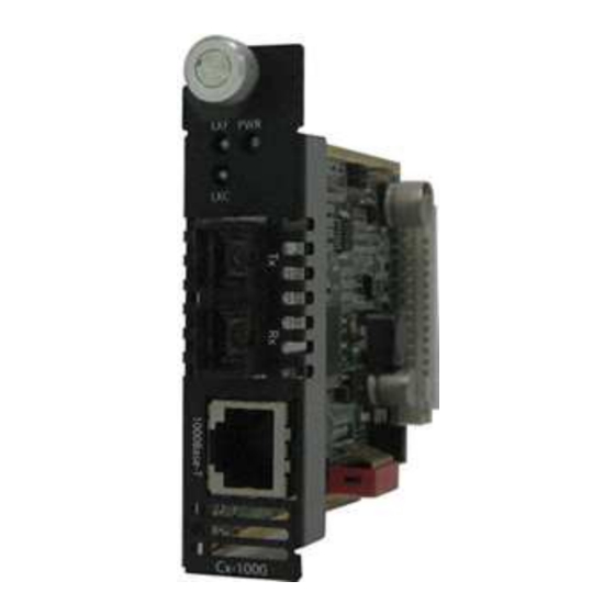
Perle Gigabit Media Converter Module Installation Guide C-1000-XXXXX Unmanaged Module CM-1000-XXXXX Managed Module C-1000-SFP Unmanaged Module CM-1000-SFP Managed Module P/N 5500305-20... - Page 2 This document contains instructions necessary for the installation and operation of the Perle Gigabit Ethernet Media Converter Module(s) that are used in conjunction with a Perle MCR chassis. The C-1000 are unmanaged media converter modules, and the CM-1000 are the managed versions. This product converts a 1000Base-TX cable connection (copper) to a 1000Base-X connection (fiber).
- Page 3 Note 1 CM-1000-SFP Note 1: Fiber characteristics will depend on the SFP fiber module selected Please refer the Perle web site for the most up to date Installation guides, models and specifications: http://www.perle.com/ Gigabit Media Converter Module – Installation Guide...
-
Page 4: Installation
UP position) will work for most installations. See the Operations section of this guide for more details. The following steps are used to configure the Perle Gigabit Media Converter Module: 1. Insert SFP Module (SFP Models only ) 2. -
Page 5: Dip Switches
Ethernet parameters on both the copper and the fiber connection. This will ensure the most optimal connection parameters will be in effect. If connecting to another Perle Gigabit Media Converter, this parameter should be set to Auto. Off: Fiber Negotiation should only be turned off, if the fiber... - Page 6 Link Mode (Switch 2) Switch Position Mode Up (default) Standard Mode Down Smart Link Pass-Through Mode Standard Mode: In this mode (if Fiber Negotiation is set to OFF), the links on the fiber and copper sides can be brought up and down independently of each other.
- Page 7 Pass-Through enabled, a loss of fiber link on either the transmit or receive line will be passed through to the local copper connection thus notifying the connected device. If the Media Converter Module has been set to Smart Link Pass- Through mode, the effect will be the same as FFA, since the link loss on the fiber receiver will result in bringing down the copper link, which will in turn cause the transmit fiber link to be brought...
- Page 8 Duplex (Switch 4) Switch Position Mode Up (default) Auto Down Half Auto: When Fiber Negotiation has been turned off (SW 1), the Media Converter Module will use this Duplex setting for its Ethernet parameter negotiation on the copper connection. In the Auto position, the Media Converter will advertise support for both Full and Half Duplex mode.
- Page 9 setting on the Media Converter Module should match the capabilities of the far end device. Loopback (Switch 6) Switch Position Mode Up (default) Disabled Down Enabled Disabled: The loopback feature is disabled. This is the normal position for regular operation. The switch must be set to this position in order for data to pass through the Media Converter Module.
-
Page 10: Installing Or Replacing Media Converter Modules
Media Converter Module(s) into the Chassis. Failure to observe this caution could result in damage to the Module(s) and/or chassis. The Perle Media Converter Modules can be installed in any available slot and in any order within the chassis. Installing or Replacing a Media Converter Module 1. - Page 11 6. Tighten the captive retainer screw to ensure the Media Converter Module is locked in place. 7. Remove the dust cap from the fiber connector and connect the fiber and copper cables. Removing Media Convert Modules 1. Loosen the captive retainer screw on the front of the Media Converter Module and gently pull the module out.
-
Page 12: Installing The Copper Cable
Installing the Copper Cable Locate 1000Base-TX compliant copper cables with male, RJ- 45 connectors installed at both ends. Connect the RJ-45 cable between the Perle Media Converter Module and the device. Note: Since the Media Converter Module supports Auto-MDIX, either a straight-through or cross over Ethernet cable may be used. -
Page 13: Operation
Operation Status LED The Perle Gigabit Media Converter Modules have three single color status LEDs located on the face plate of the module. PWR - Power/Test On: Power is on, module is operating normally Blinking slowly: the module is in loopback mode. -
Page 14: Other Features
Other Features Default Operating Mode: In the default operating mode (all switches up), the Media Converter Module will auto-negotiate on both the fiber and the copper links at the same time, thus achieving the best end-to-end Ethernet operating parameters. If the fiber link is not present, it will still permit the copper link to be established, but will not negotiate a fiber link if the copper link is not present. -
Page 15: Troubleshooting
Troubleshooting General Ensure the module is securely seated in the chassis. The PWR LED on the module should be on solid. Ensure both devices on either end of the fiber are compatible. If using a simplex fiber connection, ensure that you have both an Upstream (U) and Downstream (D) Media Converters. - Page 16 Media Converters should be lit. Data should pass through the local converter, over the fiber connection to the remote converter. At the remote converter, the data will be looped back and passed through the fiber, once again, to pass through the local converter to the copper link.
-
Page 17: Technical Specifications
Technical Specifications Power Input/Consumption 12V DC / 3.0 W Operating Temperature: 0 ° C to 50 ° C (32 ° F to 122 ° F) Storage Temperature: -25 ° C to 70 ° C (-13 ° F to 158 ° F) Operating Humidity: 5% to 90% non-condensing Storage Humidity... - Page 18 Ethernet Copper Cabling Requirements Category 5 UTP or STP 24-22 AWG Straight through or Ethernet crossover Note: Please refer the product page on the Perle website for the most up to date models and specifications. http://www.perle.com/ Gigabit Media Converter Module – Installation Guide...
-
Page 19: Compliance Information
Compliance Information This product has been found to comply with the limits for a Class A digital device, pursuant to Part 15 of the FCC rules. These limits are designed to provide reasonable protection against harmful interference when the equipment is operated in a commercial environment. -
Page 20: Warranty Registration
Warranty / Registration Perle’s standard Lifetime Warranty provides customers with return to factory repairs for Perle products that fail under the conditions of the warranty coverage. Details can be found at: http://www.perle.com/support_services/warranty.shtml Contacting Technical Support Contact information for the Perle Technical Assistance Center (PTAC) can be found at the link below.
Need help?
Do you have a question about the C-1000-XXXXX and is the answer not in the manual?
Questions and answers