Table of Contents
Advertisement
For Parts Call 606-678-9623 or 606-561-4983
Professional Shop Manual
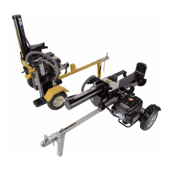
2010 and Newer Log Splitter
NOTE: These materials are for use by trained technicians who are experienced in the service and repair of outdoor power
equipment of the kind described in this publication, and are not intended for use by untrained or inexperienced individuals.
These materials are intended to provide supplemental information to assist the trained technician. Untrained or inexperi-
enced individuals should seek the assistance of an experienced and trained professional. Read, understand, and follow all
instructions and use common sense when working on power equipment. This includes the contents of the product's Oper-
ators Manual, supplied with the equipment. No liability can be accepted for any inaccuracies or omission in this publication,
although care has been taken to make it as complete and accurate as possible at the time of publication. However, due to
the variety of outdoor power equipment and continuing product changes that occur over time, updates will be made to these
instructions from time to time. Therefore, it may be necessary to obtain the latest materials before servicing or repairing a
product. The company reserves the right to make changes at any time to this publication without prior notice and without
incurring an obligation to make such changes to previously published versions. Instructions, photographs and illustrations
used in this publication are for reference use only and may not depict actual model and component parts.
© Copyright 2010 MTD Products Inc. All Rights Reserved
www.mymowerparts.com
Advertisement
Table of Contents

Subscribe to Our Youtube Channel
Related Manuals for MTD 2010


Summary of Contents for MTD 2010
- Page 1 Instructions, photographs and illustrations used in this publication are for reference use only and may not depict actual model and component parts. © Copyright 2010 MTD Products Inc. All Rights Reserved www.mymowerparts.com...
- Page 2 For Parts Call 606-678-9623 or 606-561-4983 www.mymowerparts.com...
-
Page 3: Table Of Contents
Description of the 2010 log splitters ........ - Page 4 For Parts Call 606-678-9623 or 606-561-4983 Chapter 8: Maintenance ..................61 Lubrication ........... . . 61 Beam and wedge .
-
Page 5: Chapter 1: Introduction
• Common sense in operation and safety is assumed. • In no event shall MTD be liable for poor text interpretation or poor execution of the procedures described in the text. • If the person using this manual is uncomfortable with any procedures they encounter, they should seek the help of a qualified technician or MTD Technical Support. - Page 6 For Parts Call 606-678-9623 or 606-561-4983 2010 Log Splitters • Be prepared in case of emergency: ! CAUTION ! CAUTION Keep a fire extinguisher nearby Keep a first aid kit nearby Keep emergency contact numbers handy • Replace any missing or damaged safety labels on shop equipment.
-
Page 7: Fasteners
Some instructions may refer to other parts of the manual for subsidiary procedures. This avoids repeating the same procedure two or three times in the manual. Description of the 2010 log splitters For the 2010 model year, MTD re-designed its log split- ter line. The re-designed models can be identified by:... -
Page 8: Understanding Model And Serial Numbers
24AA5DMK029. This manual is likely to carry useful information for a range of similar log splitters that may carry a variety of MTD and private brand names. Figure 1.2 The break down of what the model number means is as follows: •... -
Page 9: Chapter 2: Engine And Pump
CHAPTER 2: ENGINE AND PUMP MTD log splitters are available with a variety of horizontal and vertical shaft engines. This manual covers proce- dures that are the same for all engine models available. Specific engine procedures are covered in the engine’s ser- vice manual. - Page 10 For Parts Call 606-678-9623 or 606-561-4983 2010 Log Splitters NOTE: If the engine is not being replaced, skip to step 10. Remove the set screw in the engine coupling using Set screw a 1/8” hex key. See Figure 2.3. NOTE: When installing the engine coupling, apply a small amount of releasable thread locking compound such as Loctite®...
-
Page 11: Vertical Shaft Engines
For Parts Call 606-678-9623 or 606-561-4983 Engine and pump Vertical shaft engines To remove/replace the engine: Remove the three engine mounting screws using a 1/2” wrench. Remove the engine from the log splitter. NOTE: If the engine is being replaced, continue to step 3. Remove the set screw in the engine coupling using a 1/8”... -
Page 12: Engine Coupler Gap
Engine coupler gap MTD uses jaw type couplers to connect the engine to the pump. Jaw type couplers are made of three parts; two metallic coupler halves and a polymer spacer referred to as a spider. This type of coupling will isolate the engine vibration from the pump. -
Page 13: Pump Removal/Replacement
For Parts Call 606-678-9623 or 606-561-4983 Engine and pump Pump removal/replacement To remove the pump: Place a suitable container, large enough to hold all of the fluid in the reservoir under the pump. NOTE: On models with a vertical shaft engine, remove the engine by following the procedures described in the vertical shaft engine section of this chapter. - Page 14 Set screw NOTE: DO NOT use teflon tape on any fitting on an MTD log splitter. Pieces of the tape can get into the system and damage the valve or the pump. NOTE: Apply a light coat of oil to the O-rings before Figure 2.13...
-
Page 15: Chapter 3: Hydraulic Diagnosis
For Parts Call 606-678-9623 or 606-561-4983 Hydrualic Diagnosis CHAPTER 3: HYDRAULIC DIAGNOSIS OVERVIEW The main components of the log splitter are all fairly expensive. Hip-shot diagnosis will result in wasted time and money for the dealer. Throwing wrong parts at a log splitter gets expensive fast. Troubleshooting is a process of developing and testing theories about the problem that caused the customer to bring the log splitter in for repair. -
Page 16: Understanding The Hydraulic Flow
For Parts Call 606-678-9623 or 606-561-4983 2010 Log Splitters Understanding the hydraulic flow It starts at the reservoir (tank). See Figure 3.2. • The tank acts as the axle of the log splitter. • Check the level of the hydraulic fluid, and add hydraulic fluid through the oil fill port. - Page 17 For Parts Call 606-678-9623 or 606-561-4983 Hydrualic Diagnosis Pressurized line to The pump draws fluid from the tank, and forces it under the control valve pressure to the control valve. See Figure 3.4. Pump • The pump is capable of producing 3,400 PSI (234 bar) at a pump speed of 3,500 RPM.
- Page 18 For Parts Call 606-678-9623 or 606-561-4983 2010 Log Splitters The open-center control valve does four things: See Figure 3.6. Regulate: It regulates fluid pressure. • If the pressure exceeds a pre-set limit, the relief valve opens, returning fluid directly to the tank.
- Page 19 For Parts Call 606-678-9623 or 606-561-4983 Hydrualic Diagnosis The Cylinder See Figure 3.7. Cylinder • Both ports of the cylinder are connected to the control valve. • When pressure is applied to the port at the base of the cylinder (through the flexible high-pressure hose), the ram extends.
-
Page 20: Log Splitter Test Procedures
For Parts Call 606-678-9623 or 606-561-4983 2010 Log Splitters Log splitter test procedures Preparation Troubleshooting and diagnosing a hydraulic system is a process that should be performed in a specific order. This chapter is laid out in the order the tests should be performed to get the best results. - Page 21 For Parts Call 606-678-9623 or 606-561-4983 Hydrualic Diagnosis Fluid not getting to the pump See Figure 3.11. • If fluid is not reaching the pump, the log splitter will not work • Continued running with a dry pump will destroy the pump.
- Page 22 For Parts Call 606-678-9623 or 606-561-4983 2010 Log Splitters Inspect the tank vent: See Figure 3.13. Vent • The tank vent is drilled through the pipe plug. • As the fluid moves from the tank to the cylinder, it draws air in. As fluid moves from the cylinder back to the tank, air is forced out of the tank.
- Page 23 Confirm that the needle valve on the test gauge set is fully open and all connections are tight. NOTE: DO NOT use teflon tape on any fitting on a MTD log splitter. Pieces of the tape can get into the system and damage the valve or the pump.
- Page 24 For Parts Call 606-678-9623 or 606-561-4983 2010 Log Splitters Pump base-line test (ram stationary) Perform all of the procedures described in the preparation section of this chapter. With the engine running, record the engine RPMs on the worksheet at the end of this chapter.
- Page 25 For Parts Call 606-678-9623 or 606-561-4983 Hydrualic Diagnosis Slowly close the needle valve to build 2,000 PSI (220 Bars). See Figure 3.19. Do NOT exceed 3,200 PSI (220 Bars). This test is performed up- stream of the relief valve in the log splitter hydraulic system, rendering the relief valve ineffective during the test.
- Page 26 For Parts Call 606-678-9623 or 606-561-4983 2010 Log Splitters Control valve test Turn off the engine. Relieve hydraulic pressure from the system by moving the lever on the control valve through it’s full range of travel. Remove the test gauges from between the pump and the control valve.
-
Page 27: What To Do About Failures
For Parts Call 606-678-9623 or 606-561-4983 Hydrualic Diagnosis Extend the cylinder fully using the log splitter control Relief Valve Settings valve. Relief valve • As the ram reaches the end of its travel, pressure Valve part Tonnage setting will build until the relief valve opens. number + 100 PSI •... -
Page 28: System Drawings
For Parts Call 606-678-9623 or 606-561-4983 2010 Log Splitters System drawings Control valve in Neutral Figure 3.21 • The pump drives hydraulic fluid to the control valve. • Fluid is shunted directly back to the reservoir • No cylinder movement results... - Page 29 For Parts Call 606-678-9623 or 606-561-4983 Hydrualic Diagnosis Control valve in Extend (splitting) Figure 3.22 • The pump drives hydraulic fluid to the control valve. • The spool in the control valve directs pressurized fluid to the base end of the cylinder. •...
- Page 30 For Parts Call 606-678-9623 or 606-561-4983 2010 Log Splitters Control valve in Retract Figure 3.23 • The pump drives hydraulic fluid to the control valve. • The spool in the control valve directs pressurized fluid to the ram end of the cylinder.
- Page 31 For Parts Call 606-678-9623 or 606-561-4983 Hydrualic Diagnosis Relief in Neutral Figure 3.24 • This drawing shows the relief valve in action with the control valve in neutral. • The relief action is the same no matter what position the control valve is in. •...
- Page 32 For Parts Call 606-678-9623 or 606-561-4983 2010 Log Splitters www.mymowerparts.com...
-
Page 33: Log Splitter Hydraulic System Work Sheet
Model number be paid Serial number NOTE: Detailed hydraulic system testing instructions can be found in the 2010 and Newer Log Splitters man- Pump number ual, form number 769-06184. Preparation Valve number... - Page 34 For Parts Call 606-678-9623 or 606-561-4983 Continue closing the needle valve until the Pressure Mode Flow Capacities pressure gauge reads 2,000 PSI. Record the following: GPM/LPM Pump Tonnage Engine RPM + 0.5 GPM Flow meter reading 718-04127 21,25 and 27 1.5 (5.6 lpm) Pressure reading 718-04729...
-
Page 35: Chapter 4: Control Valve
NOTE: The only parts of the control valve that are service- able are the spring cover, lever, master link and the lever bracket. NOTE: DO NOT use teflon tape on any fitting on a MTD log splitter. Pieces of the tape can get into the sys- Figure 4.1 tem and damage the valve or the pump. - Page 36 For Parts Call 606-678-9623 or 606-561-4983 2010 Log Splitters Disconnect the high pressure hose from the pump. Disconnect the high pressure supply hose from the valve using a 15/16” wrench. See Figure 4.3. Disconnect the high pressure hose that connects the valve to the base of the cylinder.
- Page 37 For Parts Call 606-678-9623 or 606-561-4983 Control valve 12. Hold the straight fitting with a 1” wrench. Jam nut See Figure 4.6. 13. Back off the jam nut using a 7/8” wrench. See Figure 4.6. 14. Unthread the straight fitting and valve from the cylin- der.
- Page 38 For Parts Call 606-678-9623 or 606-561-4983 2010 Log Splitters To install the valve: Cylinder Transfer the elbows orientation mark to the new valve. Check or replace the O-rings on the fittings. Thread the elbow into the valve, hand tight, until it is aligned with the orientation mark.
-
Page 39: Control Valve Spring Cover
For Parts Call 606-678-9623 or 606-561-4983 Control valve To replace the valve spring cover: NOTE: The spring cover part number is 718-0522. Thoroughly clean the valve and surrounding area. NOTE: Any dirt or debris that gets inside the valve can destroy it. -
Page 40: Control Valve Lever Bracket
For Parts Call 606-678-9623 or 606-561-4983 2010 Log Splitters Control valve lever bracket To replace the lever bracket: NOTE: The lever bracket part number is 718-04765. Thoroughly clean the valve and surrounding area. NOTE: Any dirt or debris that gets inside the valve can destroy it. -
Page 41: Chapter 5: Cylinder
For Parts Call 606-678-9623 or 606-561-4983 CYLINDER CHAPTER 5: CYLINDER Cylinder removal To remove/replace the cylinder: With the engine turned-off, relieve hydraulic pressure from the system by moving the lever on the control valve through it’s full range of travel. Hydraulic fluid under high pressure can be dangerous. - Page 42 For Parts Call 606-678-9623 or 606-561-4983 2010 Log Splitters Log dislodger Remove the six screws that secure the log dislodger to the beam using a 9/16” wrench. See Figure 5.3. Figure 5.3 Remove the nut and bolt that attach the wedge to the cylinder ram using a pair of 3/4”...
-
Page 43: Cylinder Rebuilding
CYLINDER Cylinder rebuilding The cylinder used on the MTD log splitter come from two different suppliers but have the same part number. When replacing the whole cylinder, the two are interchangeable. However, when rebuilding the cylinder, the manu- facturer (type) of the cylinder must be identified so that the proper rebuild kit can be ordered. The cylinders are iden- tified as E-type and X-type. - Page 44 For Parts Call 606-678-9623 or 606-561-4983 2010 Log Splitters To rebuild a cylinder: The procedures to rebuild an “E-type” or an “X-type” cylinder are the same. Hot hydraulic fluid can cause burns. Do not work on the cylinder until the hydraulic system has cooled to ambient temperature after use.
- Page 45 For Parts Call 606-678-9623 or 606-561-4983 CYLINDER Ratchet strap Wrap a ratchet strap around the wedge and the base plate. See Figure 5.9. 10. Hold the control valve in the extend position. NOTE: A bungee cord can be used to hold the control valve in the extend position.
- Page 46 For Parts Call 606-678-9623 or 606-561-4983 2010 Log Splitters Remove the nut and bolt that attached the wedge to the cylinder ram using a pair of 3/4” wrenches. See Figure 5.12. Wedge bolt Figure 5.12 Rod guide Place the cylinder in a vise with padded jaws.
- Page 47 For Parts Call 606-678-9623 or 606-561-4983 CYLINDER 22. Clean the paint from the inside edge of the cylinder. See Figure 5.15. NOTE: Paint on the inside edge of the cylinder can catch the back-up ring, pulling it out of the grove and wedging between the rod guide and the cylinder wall.
- Page 48 For Parts Call 606-678-9623 or 606-561-4983 2010 Log Splitters Carefully pry the outer piston seal off of the piston. Outer seal See Figure 5.17. Carefully pry the O-ring out of the groove in the pis- ton. O-ring Install a new O-ring and outer piston seal.
- Page 49 For Parts Call 606-678-9623 or 606-561-4983 CYLINDER 37. Install a new back-up ring in the groove, positioned at Back-up ring the edge of the groove that is closer to the side of the rod guide that has the screw holes. 38.
- Page 50 For Parts Call 606-678-9623 or 606-561-4983 2010 Log Splitters Tighten the screws and washers to lock the rod guide in place. See Figure 5.22. Put the cylinder in its normal operating position. Attach the wedge to the ram. Attach the log dislodger.
-
Page 51: Chapter 6: Wedge And Beam
Wedge Starting with 2010 production, MTD log splitters have a new beam design. The new beam is made from a heavy gauge U-channel with a flat plate welded to the top. This replaces the old extruded I-beam design. The new beam is machined to tighter tolerances then the old design, eliminating the need for an adjustable gib. -
Page 52: Beam
For Parts Call 606-678-9623 or 606-561-4983 2010 Log Splitters Beam To remove/replace the beam: With the engine turned-off, relieve hydraulic pressure from the system by moving the lever on the control valve through it’s full range of travel. NOTE: If the shop has equipment that can safely lift the cylinder without straining the hydraulic lines, this job can be done without disconnecting the hoses. - Page 53 For Parts Call 606-678-9623 or 606-561-4983 Wedge and Beam Remove the six screws that attach the log dislodger to the beam using a 9/16” wrench. See Figure 6.5. NOTE: The 33 ton models only have four screws. Remove the dislodger from the log splitter. Dislodger Figure 6.5 10.
- Page 54 For Parts Call 606-678-9623 or 606-561-4983 2010 Log Splitters Remove the log trays by removing screws that attach them to the beam using a 1/2” wrench. See Figure 6.8. Log tray Figure 6.8 Pull on the locking pin and rotate it until it stays in the unlocked position.
-
Page 55: Chapter 7: Tank And Tires
For Parts Call 606-678-9623 or 606-561-4983 Tank and Tires CHAPTER 7: TANK AND TIRES Tank To remove/replace the tank: With the engine turned-off, relieve hydraulic pressure from the system by moving the lever on the control valve through it’s full range of travel. Hydraulic fluid under high pres- sure can be dangerous. - Page 56 For Parts Call 606-678-9623 or 606-561-4983 2010 Log Splitters Return hose Disconnect the return hose from the oil filter hous- ing. See Figure 7.3. Remove the oil filter housing by following the steps described in the oil filter housing section of this chapter.
- Page 57 For Parts Call 606-678-9623 or 606-561-4983 Tank and Tires 14. Remove the wheel assemblies by following the pro- cedures described in the wheel assembly section of this chapter. 15. Remove the fenders by following the procedures described in the fender section of this chapter. Tongue 16.
-
Page 58: Wheel Assembly
For Parts Call 606-678-9623 or 606-561-4983 2010 Log Splitters Wheel assembly To remove/replace the wheel assembly: NOTE: The wheel bearings are covered in Chapter 8: Maintenance. Lift and safely support the rear of the log splitter. Pry off the dust cap. See Figure 7.6. -
Page 59: Fenders
For Parts Call 606-678-9623 or 606-561-4983 Tank and Tires Fenders There are a variety of fenders available for MTD log splitters. They can be broken down to two types of fenders; plastic or metal. Plastic fenders To remove/replace a plastic fender:... - Page 60 NOTE: The left and the right fenders have the same part number. NOTE: There are a lot of bolt holes in the fender to accommodate all the different models of log splitters that MTD makes. To find the right bolt holes to use: Figure 7.11 •...
-
Page 61: Oil Filter Housing
Loctite® 569 to the threads of the tank nip- ple. See Figure 7.14. NOTE: DO NOT use teflon tape on any fitting on a MTD log splitter. Pieces of the tape can get into the sys- tem and damage the valve or the pump. - Page 62 For Parts Call 606-678-9623 or 606-561-4983 2010 Log Splitters Thread the oil filter housing onto the tank nipple. NOTE: There is an arrow cast into the oil filter hous- ing. The arrow must be pointing to the tank. See Figure 7.15.
-
Page 63: Vertical Locking Rod
For Parts Call 606-678-9623 or 606-561-4983 Tank and Tires Vertical locking rod To remove the vertical locking rod: Pry the push cap off of the vertical locking rod. See Figure 7.17. Remove the spring. Push cap Slide the locking rod out of the uprights on the tank. Spring Figure 7.17 To install the vertical locking rod:... -
Page 64: Horizontal Locking Rod
For Parts Call 606-678-9623 or 606-561-4983 2010 Log Splitters Horizontal locking rod To remove/replace the horizontal locking rod: Move the beam to the vertical splitting position. Dive out the roll pin using a 1/8” pin punch. See Figure 7.19. Pull the locking rod out of the bracket, catching the spring when the rod is removed. -
Page 65: Chapter 8: Maintenance
For Parts Call 606-678-9623 or 606-561-4983 Maintenance CHAPTER 8: MAINTENANCE Lubrication To help keep the MTD log splitter in proper running order, MTD recommends the following maintenance intervals be used (adjustable to local conditions). Maintenance Point Interval Clean beam and wedge... -
Page 66: Engine Maintenance
Fuel used in MTD outdoor power equipment should be no more than 30 days old. Because it may already have been stored at the refinery or gas station for a week or more, fuel should be purchased in small quantities and stored in safety approved gas cans with the caps closed. -
Page 67: Engine Oil
SM. Motor oils classified SM will show this designation on the container. Synthetic oil is a suitable alternative, but it does not extend service intervals. NOTE: MTD recommends the use of petroleum oil during the break in period to ensure the piston rings break in correctly. -
Page 68: Hydraulic Oil
Hydraulic oil The MTD log splitter has an open vent in the dip stick plug. This leave the hydraulic oil in the reservoir open to collect dirt and water from the atmosphere. Because of this, the hydraulic oil should be changed ever 100 hours. -
Page 69: Wheel Bearings
Wheel bearings The wheel bearing on the MTD log splitter will need to be serviced from time to time. The frequency of how often they need to be serviced depends on how the splitter is towed. A splitter that was towed home from the store and parked in the yard, never moving, will not need to have the bearings serviced as often as the splitter that gets towed from job site to job site. - Page 70 For Parts Call 606-678-9623 or 606-561-4983 2010 Log Splitters Clean and inspect the bearing races. NOTE: If there are signs of wear or damage to a bearing race, it and its matching cone must be replaced. NOTE: To replace a race: •...
- Page 71 For Parts Call 606-678-9623 or 606-561-4983 www.mymowerparts.com...
- Page 72 For Parts Call 606-678-9623 or 606-561-4983 MTD Products Inc - Product Training and Education Department FORM NUMBER - 769-06184 07/2010 www.mymowerparts.com...
Need help?
Do you have a question about the 2010 and is the answer not in the manual?
Questions and answers