HP 1810-8 Installation And Getting Started Manual
1810 switch series
Hide thumbs
Also See for 1810-8:
- Management and configuration manual (71 pages) ,
- Quick start manual (5 pages)

Related Manuals for HP 1810-8


Summary of Contents for HP 1810-8
- Page 1 HP 1810 Switch Series Installation and Getting Started Guide HP 1810-8 Switch (J9800A) HP 1810-24 Switch (J9801A) HP 1810-8G Switch (J9802A) HP 1810-24G Switch (J9803A) Power over Ethernet PD...
- Page 3 HP 1810 Switch Series Installation and Getting Started Guide...
- Page 4 Hewlett-Packard assumes no responsibility for the use or reliability of its software on equipment that is not furnished by Hewlett-Packard. Warranty For the latest license and warranty information, visit www.hp.com/networking/support. A copy of the specific warranty terms applicable to your Hewlett-Packard products and replacement parts can be obtained from your HP Sales and Service Office or authorized dealer.
-
Page 5: Table Of Contents
Contents 1 Switch Overview Switch Hardware Features ........1-2 Network Ports . - Page 6 Testing the Switch by Resetting It ....... . . 4-4 Restoring to Factory Defaults .
-
Page 7: Switch Overview
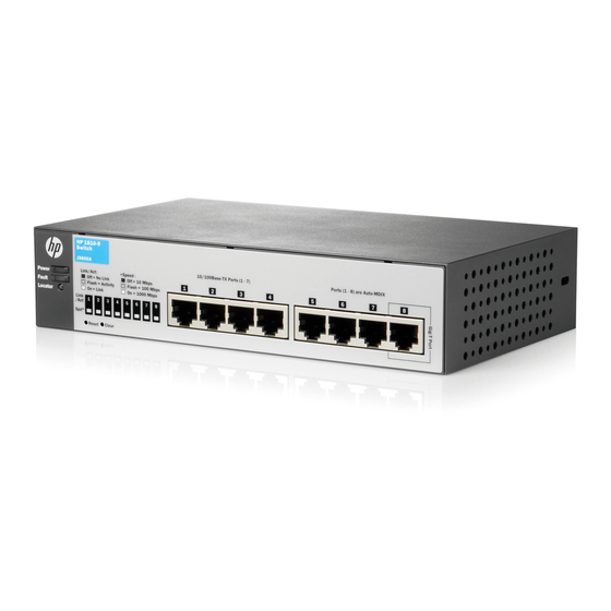
These switches are store-and-forward devices that offer low latency for high-speed networking. Throughout this manual, these switches will be referred to as the 1810-8 Switch, 1810-24 Switch, 1810-8G Switch, and the 1810-24G Switch. The 1810-8 Switch has 7 auto-sensing 10/100BASE-TX RJ-45 ports and one ■... -
Page 8: Switch Hardware Features
Switch Overview Switch Hardware Features Switch Hardware Features HP 1810-8 Switch (J9800A) Link/Act and Speed LEDs Power and Fault LEDs Locator LED 10/100/1000BASE-T RJ-45 port 10/100BASE-TX RJ-45 ports Reset and Clear buttons HP 1810-24 Switch (J9801A) Power, Fault, and Link/Act and Speed LEDs... -
Page 9: Network Ports
Switch Overview Switch Hardware Features HP 1810-24G Switch (J9803A) Power, Fault, and Link/Act and Speed LEDs Locator LEDs Reset and Clear buttons SFP slots 10/100/1000BASE-T RJ-45 ports All RJ-45 ports have the Auto-MDIX feature. Network Ports Auto-sensing 10/100BASE-TX ports. ■ All these ports have the “Auto-MDIX”... -
Page 10: Leds
Switch Overview Switch Hardware Features For supported transceivers, visit www.hp.com/networking/support – In the first textbox, type J4858 (for 100-Mb and Gigabit information). – Select any of the products that display in the dropdown list. Click the Display selected button. – Select Product support information. Then click Manuals and find the Transceiver Support Matrix. -
Page 11: Reset Button
Switch Overview Switch Hardware Features State Meaning Indicates the port is operating at 1000 Mbps. (green) Blinking Indicates the port is operating at 100 Mbps. Indicates the port is operating at 10 Mbps. * The blinking behavior is an on/off cycle once every 1.6 seconds, approximately. ** The blinking behavior is an on/off cycle once every 0.8 seconds, approximately. -
Page 12: Switch Features
Switch Overview Switch Features The 1810-8 and 1810-8G Switches do not have a power switch, they are powered on when the external AC/DC power adapter is connected to the switch and to a power source. The external AC/DC power adapter supplies 12 volts DC to the switch and automatically adjusts to any AC voltage between 100-240 volts and either 50 or 60 Hz. - Page 13 Switch Overview Switch Features • ProCurve Manager (PCM) — allows network administrators to discover and map the switches within their network and launch the built-in graphical interface from within PCM to configure the switches. ■ support for up to 128 IEEE 802.1Q-compliant VLANs so you can divide the attached end nodes into logical groupings that fit your business needs.
- Page 14 Switch Overview Switch Features...
-
Page 15: Installing The Switch
• Software License, Warranty, and Support information Accessory kits: ■ 1810-24 and 1810-24G Switch 1810-8 and 1810-8G Switch Kit number 5066-0620 Kit number 5066-0621 • three 3/4” (20-mm M4) screws for wall and • three 3/4” (20-mm M4) screws for wall... - Page 16 8121-0964 Argentina 8120-6871 Brazil 8121-1069 Chile 8120-6979 1810-8 and 1810-8G external AC/DC power adapters and power cords, one ■ of the following: • Universal Inline AC/DC Power Adapter All countries/regions 5066-1122 Power Cords for Inline AC/DC Power Adapter Australia/New Zealand...
-
Page 17: Installation Precautions
Installing the Switch Included Parts Installation Precautions Follow these precautions when installing the switch. ■ The rack or cabinet should be adequately secured to prevent it W A R N I N G from becoming unstable and/or falling over. Devices installed in a rack or cabinet should be mounted as low as possible, with the heaviest devices at the bottom and progres- sively lighter devices installed above. -
Page 18: Installation Procedure
19-inch telco rack, in an equipment cabinet, on a wall, under a table, or on a horizontal surface. The 1810-8 and 1810-8G Switches can be mounted on a wall, under a table, or on a horizontal surface. -
Page 19: Prepare The Installation Site
For the 1810-8 and 1810-8G Switches, connect the AC/DC adapter’s power cord to the power connector on the back of the switch, and then plug the... - Page 20 Installation Procedure 1810-24 and 1810-24G Switch Connect the power cord to the switch and an AC power outlet 1810-8 and 1810-8G Switch Connect inline AC/DC power adapter to the switch and an AC power outlet Connect wall plug-in AC/DC power adapter...
- Page 21 50 or 60 Hz. There are no voltage range settings required. The 1810-8 and 1810-8G Switches also do not have a power switch. They are powered on when the external AC/DC power adapter is connected to the switch and the adapter power cord to a power source.
-
Page 22: Mount The Switch
Installing the Switch Installation Procedure If the ports are connected to active network devices, the Link/Act – LEDs stay on or may be blinking to indicate port activity. The Spd LEDs turn on for 1000 Mbps links, blink for 100 Mbps links, or stay off for 10 Mbps links. - Page 23 Installing the Switch Installation Procedure Use a #1 Phillips (cross-head) screwdriver and attach the mounting brackets to the switch with the included 8-mm M4 screws. 8 mm M4 screws N o t e The mounting brackets have multiple mounting holes and can be rotated allowing for a wide variety of mounting options.
- Page 24 Installing the Switch Installation Procedure Wall Mounting You can mount the switch on a wall with the front panel facing up. W A R N I N G For safe operation, please read the “Installation Precautions” on page 2-3 page 2-3, before mounting the switch.
- Page 25 Installing the Switch Installation Procedure Under-Table Mounting You can mount the switch under a wood table. C a u t i o n The switch should be mounted only to a table surface that is at least 3/4-inch (19.1 mm) thick. Install two 5/8-inch (15.875 mm) Number 12 wood screws, (included) into the mounting surface, positioned 5.5 inches (140mm) apart for the 1810- 8 and 1810-8G Switch, or positioned 10 inches (254 mm) apart for the 1810-...
- Page 26 Installing the Switch Installation Procedure Horizontal Surface Mounting Place the switch on a table or other horizontal surface. The switch comes with rubber feet in the accessory kit that can be used to help keep the switch from sliding on the surface. Attach the rubber feet to the four corners on the bottom of the switch within the embossed angled lines.
-
Page 27: Connect The Switch To A Power Source
AC/DC power adapter into a nearby AC power source. 2.) Re-check the LEDs during self test. See “Self Test LED Behavior” on page 2-7. For the 1810-8 and 1810-8G Switch, use the included cable tie to secure the power cord to the switch. 2-13... -
Page 28: Connect The Network Cables
Installing the Switch Installation Procedure 5. Connect the Network Cables Connect the network cables, from the network devices or your patch panels, to the fixed RJ-45 ports on the switch or to any SFP transceivers you have installed in the switch. RJ-45 connector 100-ohm unshielded or shielded twisted- pair cable:... -
Page 29: Installing Or Removing Sfps
Installing the Switch Installation Procedure 6. Installing or Removing SFPs You can install or remove an SFP transceiver from an SFP slot without having to power off the switch. N o t e The SFP ports operate only at full duplex. Half duplex operation is not ■... - Page 30 Installing the Switch Installation Procedure Removing the SFPs: N o t e You should disconnect the network cable from the SFP before removing it from the switch. Depending on when you purchased your HP SFP, it may have either of three different release mechanisms: a plastic tab on the bottom of the SFP, a plastic collar around the SFP, or a wire bail.
-
Page 31: Configuring The Switch
Configuring the Switch Initial Configuration The HP 1810 Switch Series can be managed through a Web-browser interface that you can access from any PC or workstation in the connected network. For initial configuration, you may want to assign an IP address to the switch that is compatible with your existing network. -
Page 32: Changing The Pc's Ip Address
Configuring the Switch Changing the PC’s IP Address N o t e If you enable DHCP for IP network configuration, the switch must be connected to the same network as the DHCP server. You will need to access your DHCP server to determine the IP address assigned to the switch. Click Maintenance >... -
Page 33: Where To Go From Here
Configuring the Switch Where to Go From Here Where to Go From Here For more information on the Web browser interface and all the features that can be configured on the HP 1810 Switch Series, see the HP 1810 Switch Series Management and Configuration Guide, which is available on the HP Web site, http://www.hp.com/networking/support... -
Page 34: Troubleshooting
Troubleshooting This section describes how to troubleshoot the switch. For more information, see the chapter “Troubleshooting” in the HP 1810 Switch Series Management and Configuration Guide, available on the HP Web site, http://www.hp.com/networking/support. This chapter describes the following: ■ basic troubleshooting tips (page 4-1) diagnosing with the LEDs... -
Page 35: Diagnosing With The Leds
Troubleshooting Diagnosing with the LEDs Diagnosing with the LEDs When resetting the switch, or during a power-on self test (POST), LED patterns on the switch may indicate a problem condition. Check in the table below for the LED pattern you see on your switch. Refer to the corresponding diagnostic tip on the next few pages. - Page 36 Troubleshooting Diagnosing with the LEDs Problem Solution ➋ A switch hardware Try power cycling the switch. If the fault indication reoccurs, the switch may have failure has occurred. failed. Call your HP authorized network reseller, or use the electronic support All the LEDs will stay services from HP to get assistance.
-
Page 37: Testing The Switch By Resetting It
Troubleshooting Testing the Switch by Resetting It Testing the Switch by Resetting It If you believe the switch is not operating correctly, you can reset the switch to test its circuitry and operating code. To reset the switch, unplug and plug in the power cord (power cycling) Power cycling the switch will cause the switch to perform its power-on self test. -
Page 38: Hp Customer Support Services
Troubleshooting HP Customer Support Services HP Customer Support Services If you are still having trouble with your switch, Hewlett-Packard offers support 24 hours a day, seven days a week through the use of a number of automated electronic services. The HP Web site, http://www.hp.com/networking/support... -
Page 39: Hp Customer Support Services
Troubleshooting HP Customer Support Services... -
Page 40: Switch Specifications
Specifications Switch Specifications Physical Width Depth Height Weight 1810-8 (J9800A) 20.15 cm (7.9 in) 11.8 cm (4.65 in) 4.4 cm (1.73 in) 0.35 kg (0.8 lbs) 1810-24 (J9801A) 33.0 cm (13.0 in) 17.45 cm (6.9 in) 4.4 cm (1.73 in) 1.41 kg (3.1 lbs) -
Page 41: Environmental
Specifications Switch Specifications Environmental Operating Non-Operating Temperature 0°C to 40°C (32°F to 104°F) -40°C to 70°C (-40°F to 158°F) Relative humidity 15% to 95% at 40°C (104°F) 15% to 95% at 65°C (149°F) (non-condensing) Maximum altitude 3.0 Km (10,000 ft)* 4.57 Km (15,000 ft) The operating maximum altitude should not exceed that of any accessory being connected to any 1810 Switch. -
Page 42: Standards
Specifications Standards Standards Technology Standards and Safety Compliance Laser safety information Technology Compatible with these IEEE EN/IEC standard standards compliance ("mini-GBIC") Lasers 10-T IEEE 802.3 10BASE-T 100-TX IEEE 802.3u 100BASE-TX 1000-T IEEE 802.3ab 1000BASE-T 100-FX IEEE 802.3u 100BASE-FX EN/IEC 60825 Class 1 Laser Product Laser Klasse 1 1000-SX... -
Page 43: Cabling And Technology Information
Specifications Cabling and Technology Information Cabling and Technology Information Cabling Specifications Cabling Specifications 10 Mbps Operation Category 3, 4 or 5, 100-ohm unshielded twisted-pair (UTP) or shielded twisted-pair (STP) cable, complying with IEEE 802.3 10BASE-T specifications. 100 Mbps Operation Category 5, 100-ohm UTP or STP cable, complying with IEEE 802.3u Twisted-pair copper 100BASE-TX specifications. -
Page 44: Technology Distance Specifications
Specifications Cabling and Technology Information Note on 1000BASE-T Cable Requirements. The Category 5 networking cables that work for 100BASE-TX connections should also work for 1000BASE-T, as long as all four-pairs are connected. But, for the most robust connections, you should use cabling that complies with the Category 5e specifications, as described in Addendum 5 to the TIA-568-A standard (ANSI/ TIA/EIA-568-A-5). -
Page 45: Mode Conditioning Patch Cord
Specifications Mode Conditioning Patch Cord Mode Conditioning Patch Cord The following information applies to installations in which multimode fiber- optic cables are connected to a Gigabit-LX port. Multimode cable has a design characteristic called “Differential Mode Delay”, which requires the transmission signals be “conditioned”... - Page 46 Specifications Mode Conditioning Patch Cord Gigabit-LX port To network multimode Mode Conditioning cabling Patch Cord Single mode section plugs into Tx The multimode cable in the patch cord port on Gigabit-LX Transceiver or must match the characteristics of your Gigabit-LX mini-GBIC network cable Example: Connecting a Mode Conditioning Patch Cord for Gigabit-LX Make sure you purchase a patch cord that has appropriate connectors on each...
-
Page 47: Twisted-Pair Cable/Connector Pin-Outs
Specifications Twisted-Pair Cable/Connector Pin-Outs Twisted-Pair Cable/Connector Pin-Outs The Auto-MDIX Feature: In the default configuration, “Auto”, the fixed 10/ 100/1000BASE-T ports on the switches all automatically detect the type of port on the connected device and operate as either an MDI or MDI-X port, whichever is appropriate. - Page 48 Specifications Twisted-Pair Cable/Connector Pin-Outs For 100 Mbps connections to the ports, use 100-ohm Category 5 UTP or ■ STP cable only, as supported by the IEEE 802.3u Type 100BASE-TX standard. ■ For 1000 Mbps connections, 100-ohm Category 5e or better cabling is recommended.
-
Page 49: Straight-Through Twisted-Pair Cable For 10 Mbps Or 100 Mbps Network Connections
Specifications Twisted-Pair Cable/Connector Pin-Outs Straight-through Twisted-Pair Cable for 10 Mbps or 100 Mbps Network Connections Because of the Auto-MDIX operation of the 10/100 ports on the switch, for all network connections, to PCs, servers or other end nodes, or to hubs or other switches, you can use straight-through cables. -
Page 50: Crossover Twisted-Pair Cable For 10 Mbps Or 100 Mbps Network Connection
Specifications Twisted-Pair Cable/Connector Pin-Outs Crossover Twisted-Pair Cable for 10 Mbps or 100 Mbps Network Connection The Auto-MDIX operation of the 10/100 ports on the switch also allows you to use crossover cables for all network connections, to PCs, servers or other end nodes, or to hubs or other switches. -
Page 51: Straight-Through Twisted-Pair Cable For 1000 Mbps Network Connections
Specifications Twisted-Pair Cable/Connector Pin-Outs Straight-Through Twisted-Pair Cable for 1000 Mbps Network Connections 1000BASE-T connections require that all four pairs of wires be connected. Cable Diagram N o t e Pins 1 and 2 on connector “A” must be wired as a twisted pair to pins 1 and 2 on connector “B”. -
Page 52: B Emc Regulatory Statements
EMC Regulatory Statements Regulatory Statements U.S.A. FCC Class A This equipment has been tested and found to comply with the limits for a Class A digital device, pursuant to part 15 of the FCC Rules. These limits are designed to provide reasonable protection against harmful interference when the equipment is operated in a commercial environment. - Page 53 EMC Regulatory Statements Regulatory Statements Japan VCCI Class A Korea Taiwan...
- Page 54 Index Numerics Clear button deleting passwords … 1-5 10/100BASE-TX ports description … 1-5 location on switch … 1-2 location on switch … 1-2, 1-5 1000BASE-T restoring factory default configuration … 1-5, fiber-optic cable specifications … A-5 configuration restoring factory defaults … 1-5 connecting the switch to a power source …...
- Page 55 horizontal surface network cables mounting switch on … 2-12 HP Auto-MDIX feature … A-8 horizontal surface, mounting switch on … 2-11 required types … 2-5 HP Auto-MDIX twisted-pair connector pin-outs … A-8 feature description … A-8 twisted-pair, wiring rules … A-8 network devices connecting to the switch …...
- Page 56 Reset button twisted-pair cable description … 1-5 cross-over cable pin-out … A-11 location on switch … 1-2, 1-5 pin-outs … A-8, A-10, A-12 restoring factory default configuration … 4-4 straight-through cable pin-out … A-10, A-12 resetting the switch switch-to-computer connection … A-10, A-12 location of Reset button …...
- Page 57 Index-4...
- Page 58 Technology for better business outcomes To learn more, visit www.hp.com/networking © Copyright 2012 Hewlett-Packard Development Company, L.P. The information contained herein is subject to change without notice. The only warranties for HP products and services are set forth in the express warranty statements accompanying such products and services.
Need help?
Do you have a question about the 1810-8 and is the answer not in the manual?
Questions and answers