HP OfficeConnect 1820 8G Installation And Getting Started Manual
Officeconnect 1820 switch series
Hide thumbs
Also See for OfficeConnect 1820 8G:
- Management and configuration manual (110 pages) ,
- Installation and getting started manual (59 pages)
Table of Contents
Advertisement
HPE OfficeConnect 1820 Switch Series
Installation and Getting Started Guide
Abstract
This guide provides information on installing and configuring the HPE OfficeConnect 1820 Switch
Series. Hardware specifications and troubleshooting information is also provided.
Part Number: 5200-2849
Published: March 2017
Edition: 1
Advertisement
Table of Contents
Troubleshooting

Related Manuals for HP OfficeConnect 1820 8G


Summary of Contents for HP OfficeConnect 1820 8G
- Page 1 HPE OfficeConnect 1820 Switch Series Installation and Getting Started Guide Abstract This guide provides information on installing and configuring the HPE OfficeConnect 1820 Switch Series. Hardware specifications and troubleshooting information is also provided. Part Number: 5200-2849 Published: March 2017 Edition: 1...
- Page 2 © 2017, 2017 Hewlett Packard Enterprise Development LP Notices The information contained herein is subject to change without notice. The only warranties for Hewlett Packard Enterprise products and services are set forth in the express warranty statements accompanying such products and services. Nothing herein should be construed as constituting an additional warranty. Hewlett Packard Enterprise shall not be liable for technical or editorial errors or omissions contained herein.
-
Page 3: Table Of Contents
Contents Switch overview...................5 Switch hardware features........................5 Network Ports........................... 8 LEDs............................8 Mode Button........................... 10 Reset button........................... 10 Power Connector........................10 Switch Features..........................10 Installing the Switch.................. 12 Included Parts............................12 Installation precautions........................14 Installation Procedure........................15 1. Prepare the installation site....................16 Installation space requirements................... 16 2. - Page 4 Support and other resources..............32 Accessing Hewlett Packard Enterprise Support................32 Accessing updates..........................32 Customer self repair.......................... 32 Remote support..........................33 Warranty information......................... 33 Regulatory information........................33 Documentation feedback........................34 Specifications.................... 35 Switch Specifications.........................35 Physical..........................35 Electrical..........................35 Environmental.........................36 Acoustics..........................36 Safety............................36 Standards............................
-
Page 5: Switch Overview
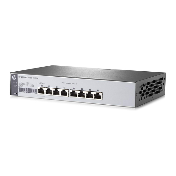
In addition, these switches offer network management capabilities. Switch hardware features HPE OfficeConnect 1820 8G Switch (J9979A) Power and Fault/Locator LEDs PoE PD port... - Page 6 10/100/1000BASE-T RJ-45 ports Reset button HPE OfficeConnect 1820 48G Switch (J9981A) Power and Fault/Locator LEDs Link/Act and Speed LEDs SFP slots 10/100/1000BASE-T RJ-45 ports Reset button HPE OfficeConnect 1820 8G PoE+ (65W) Switch (J9982A) Power and Fault/Locator LEDs Switch overview...
- Page 7 PoE+ ports 1-4 Link/Act and Mode LEDs 10/100/1000BASE-T RJ-45 ports Reset button Mode button HPE OfficeConnect 1820 24G PoE+ (185W) Switch (J9983A) Power and Fault/Locator LEDs PoE+ ports 1-12 Link/Act and Mode LEDs SFP slots 10/100/1000BASE-T RJ-45 ports Mode button Reset button HPE OfficeConnect 1820 48G PoE+ (370W) Switch (J9984A) Power and Fault/Locator LEDs...
-
Page 8: Network Ports
10/100/1000BASE-T RJ-45 ports Reset button Network Ports • Auto-sensing 10/100/1000BASE-T ports. All these ports have the “Auto-MDIX” feature, which means that you can use either straight-through or crossover twisted-pair cables to connect any network devices to the switch. • Power-over-Ethernet or PoE ports. The 1820 PoE+ switches support the IEEE 802.3at standard, which allows IP telephones, wireless LAN Access Points, and other appliances to receive power as well as data over existing LAN cabling. - Page 9 State Meaning Power (green) The switch is receiving power. Blinking* (1820 8G only) Power is available on the PoE In port (Port 1). The switch is NOT receiving power. Fault/Locator On briefly after the switch is powered on or reset, at the beginning of (orange) switch self test.
-
Page 10: Mode Button
Mode Button The 1820 PoE+ switches have one Mode LED per port. The Mode LED shows either the port speed or the PoE status. In PoE mode, it shows whether the port is configured to provide PoE power. The operation of the Mode LED is controlled by the Mode select button. - Page 11 ◦ Web browser interface — an easy to use built-in graphical interface that can be accessed from common Web browsers. ◦ Intelligent Management Center (iMC) — allows network administrators to discover and map the switches within their network and launch the built-in graphical interface from within iMC to configure the switches.
-
Page 12: Installing The Switch
Installing the Switch The 1820 Switches are easy to install. They come with an accessory kit that includes the brackets for mounting the switches in a standard 19-inch telco rack, in an equipment cabinet, and with rubber feet that can be attached so the switches can be securely located on a horizontal surface. - Page 13 Country/Region 1820 24G, 1820 48G, 1820 48G PoE+ and 1820 24G PoE+ Brazil 8121-1069 8121-1132 Chile 8120-6980 8120-8389 China 8120-8377 8121-1034 Continental Europe 8120-6802 8120-5336 Denmark 8120-6806 8120-5340 India 8121-0780 8120-5341 Israel 8121-1035 8121-1009 Japan 8120-6804 8120-5342 Switzerland 8120-6807 8120-5339 South Africa 8121-0919 8120-5341...
-
Page 14: Installation Precautions
Argentina 8120-8367 Chile 8121-0514 • Wall Plug-in AC/DC Power Adapters(AC Power cords are not used) United States/Canada/Mexico 5184-5863 Continental Europe/Denmark/Norway/Sweden/Switzerland/ 5184-5864 Israel/Vietnam/Indonesia • The 1820 8G PoE+ external AC/DC power adapters and power cords, one of the following: • Universal Inline AC/DC Power Adapter (model PA2) 5066-2164 •... -
Page 15: Installation Procedure
WARNING: • The rack or cabinet should be adequately secured to prevent it from becoming unstable and/or falling over.Devices installed in a rack or cabinet should be mounted as low as possible, with the heaviest devices at the bottom and progressively lighter devices installed above. •... -
Page 16: Prepare The Installation Site
AC/DC power adapter into a nearby properly grounded electrical outlet. HPE OfficeConnect 1820 24- and 48-port switches Connect the power cord to the switch and an AC power outlet. HPE OfficeConnect 1820 8G switch 1. Prepare the installation site... - Page 17 Connect wall plug-in AC/DC power adapter to the switch and then to an AC power outlet. HPE OfficeConnect 1820 8G PoE+ switch Connect inline AC/DC power adapter to the switch and then to an AC power outlet. NOTE: The 1820 24- and 48-port switches do not have a power switch. They are powered on when the power cord is connected to the switch and to a power source.
- Page 18 Port Link/Act and Speed LEDs Power and Fault/Locator LEDs Port Link/Act LEDs Power and Fault/Locator LEDs Mode LED When the switch is powered on, it performs a diagnostic self test. The behavior of the LEDs is as follows: During the self test: •...
-
Page 19: Mount The Switch
• The Power LED remains on. • The Fault/Locator LED stays off. • The port LEDs on the front of the switch go into their normal operational mode: ◦ If the ports are connected to active network devices, the Link/Act LEDs stay on or may be blinking to indicate port activity. -
Page 20: Wall Or Under-Table Mounting
NOTE: The mounting brackets have multiple mounting holes and can be rotated allowing for a wide variety of mounting options. These include mounting the switch so its front face is flush with the face of the rack, as shown in the illustration. 2. -
Page 21: Horizontal Surface Mounting
To mount the 1820 8-port switches, follow these steps: 1. In the required location, mark the position for the mounting screws. The hole-to-hole distance is 3.54 inch (90 mm). 2. Use a #1 Phillips (cross-head) screwdriver and two of the included 20-mm M4 tap screws. Set the screw heads approximately 2 mm away from the mounting surface to allow the switch to slide onto the screws. -
Page 22: Using A Kensington Security Cable
Using a Kensington security cable To prevent unauthorized removal of the switch, you can use a Kensington Slim MicroSaver security cable (not included) to attach the switch to an immovable object. 4. Connect the Switch to a Power Source Procedure 1. -
Page 23: Connect The Network Cables
2. Re-check the LEDs during self test. See 2 on page 17. 3. For the 1820 8-port switches, use the included cable tie to secure the power cord to the switch. 5. Connect the Network Cables Connect the network cables, from the network devices or your patch panels, to the fixed RJ-45 ports on the switch or to any SFP transceivers you have installed in the switch. -
Page 24: Installing The Sfps
NOTE: Ensure the network cable is NOT connected when you install or remove an SFP. Installing the SFPs: Remove the protective plastic cover and retain it for later use. Hold the SFP by its sides and gently insert it into any of the slots on the switch until the SFP clicks into place. WARNING: The HPE SFPs are Class 1 laser devices. -
Page 25: Configuring The Switch
Configuring the Switch Initial Configuration The 1820 Switch Series can be managed through a Web-browser interface that you can access from any PC or workstation connected to the switch. To access the Web interface, you must have the switch’s Internet Protocol (IP) address. In the factory default configuration, the IP address is automatically acquired from a Dynamic Host Configuration Protocol (DHCP) service that is available on your network or from your Internet Service Provider (ISP). -
Page 26: Using The 192.168.1.1 Ip Address
See the HPE OfficeConnect 1820 Switch Series Management and Configuration Guide for more switch configuration information. NOTE: If you cannot remember the switch’s IP address or password, you can restore the factory default settings by following the procedure described in Troubleshooting on page 27. Using the 192.168.1.1 IP address If the switch does not acquire an IP address via the DHCP request, it defaults to the following configuration: Parameter... -
Page 27: Troubleshooting
Troubleshooting Cause This section describes how to troubleshoot the switch. For more information, see the chapter “Troubleshooting” in the HPE OfficeConnect 1820 Switch Series Management and Configuration Guide, available on the Hewlett Packard Enterprise Web site, http://www.hpe.com/support/manuals. This chapter describes the following: •... -
Page 28: Diagnostic Tips
LED Pattern Indicating Problems Diagnostic Tips Power Fault Port LED Blinking† Blinking† ➌ Off with cable connected ➍ * This LED is not important for the diagnosis. † The blinking behavior is an on/off cycle once every 1.6 seconds, approximately. Diagnostic Tips Problem Solution... -
Page 29: Led Patterns For Poe Troubleshooting
Problem Solution ➌ The network port for Try power cycling the switch. If the fault indication reoccurs, the switch which the Link LED is port may have failed. To confirm, try a different port that appears to be blinking has good. -
Page 30: Testing The Switch By Resetting It
Problem Solution ➊ PoE oversubscription If possible add additional PoE power, or redefine port priorities. condition. All available PoE power is already taken by higher-priority ports. ➋ PoE hardware fault. A The switch must be replaced. switch hardware component that is involved with PoE power delivery has failed. -
Page 31: Websites
Websites Networking Websites Hewlett Packard Enterprise Networking Information www.hpe.com/networking/resourcefinder Library Hewlett Packard Enterprise Networking Software www.hpe.com/networking/software Hewlett Packard Enterprise Networking website www.hpe.com/info/networking Hewlett Packard Enterprise My Networking website www.hpe.com/networking/support Hewlett Packard Enterprise My Networking Portal www.hpe.com/networking/mynetworking Hewlett Packard Enterprise Networking Warranty www.hpe.com/networking/warranty General websites Hewlett Packard Enterprise Information Library... -
Page 32: Support And Other Resources
IMPORTANT: Access to some updates might require product entitlement when accessed through the Hewlett Packard Enterprise Support Center. You must have an HP Passport set up with relevant entitlements. Customer self repair Hewlett Packard Enterprise customer self repair (CSR) programs allow you to repair your product. If a CSR part needs to be replaced, it will be shipped directly to you so that you can install it at your convenience. -
Page 33: Remote Support
For more information about CSR, contact your local service provider or go to the CSR website: http://www.hpe.com/support/selfrepair Remote support Remote support is available with supported devices as part of your warranty or contractual support agreement. It provides intelligent event diagnosis, and automatic, secure submission of hardware event notifications to Hewlett Packard Enterprise, which will initiate a fast and accurate resolution based on your product's service level. -
Page 34: Documentation Feedback
www.hpe.com/info/reach For Hewlett Packard Enterprise product environmental and safety information and compliance data, including RoHS and REACH, see: www.hpe.com/info/ecodata For Hewlett Packard Enterprise environmental information, including company programs, product recycling, and energy efficiency, see: www.hpe.com/info/environment Documentation feedback Hewlett Packard Enterprise is committed to providing documentation that meets your needs. To help us improve the documentation, send any errors, suggestions, or comments to Documentation Feedback (docsfeedback@hpe.com). -
Page 35: Specifications
Specifications Switch Specifications Physical Width Depth Height Weight 1820 8G (J9979A) 25.4 cm (10.0 in) 15.95 cm (6.28 in) 4.4 cm (1.73 in) 0.8 kg (1.8 lb) 1820 24G (J9980A) 44.25 cm (17.42 24.61 cm (9.69 in) 4.4 cm (1.73 in) 2.7 kg (6.0 lb) 1820 48G (J9981A) 44.25 cm (17.42... -
Page 36: Environmental
AC voltage Maximum current Frequency range 1820 48G PoE+ 100-127 volts200-240 5 A / 2.5 A 50/60 Hz (J9984A) volts Requires a connection to an external power adapter. The adapter automatically adjusts to any voltage between 100 and 240 volts and either 50 or 60 Hz. The switch automatically adjusts to any voltage between 100-127 or 200-240 volts and either 50 or 60 Hz. -
Page 37: Standards
Standards Laser safety information Technology Compatible with these EN/IEC standard SFP Lasers IEEE standards compliance 10-T IEEE 802.3 10BASE-T 100-TX IEEE 802.3u 100BASE-TX 1000-T IEEE 802.3ab 1000BASE-T 100-FX IEEE 802.3u 100BASE-FX EN/IEC 60825 Class 1 Laser Product Laser Klasse 1 1000-SX IEEE 802.3z 1000BASE-SX EN/IEC 60825... -
Page 38: Technology Distance Specifications
Because of the increased speed provided by 1000BASE-T (Gigabit-T), network cable quality is more important than for either 10BASE-T or 100BASE-TX. Cabling plants being used to carry 1000BASE-T networking must comply with the IEEE 802.3ab standards. In particular, the cabling must pass tests for Attenuation, Near-End Crosstalk (NEXT), and Far-End Crosstalk (FEXT). -
Page 39: Installing The Patch Cord
Installing the Patch Cord As shown in the illustration below, connect the patch cord to the transceiver with the section of single mode fiber plugged in to the Tx (transmit) port. Then, connect the other end of the patch cord to your network cabling patch panel, or directly to the network multimode fiber. -
Page 40: Straight-Through Twisted-Pair Cable For10 Mbps Or 100 Mbps Network Connections
NOTE: Using Fixed Configurations. If the port configuration is changed to any of the fixed configurations though, for example 100 Mbps/full duplex, the port operates as MDI-X only and the correct cable type must be used: for connections to MDI ports, such as end nodes, use a straight-through cable; for connections to MDI-X ports, such as on hubs and other switches, use a crossover cable. -
Page 41: Pin Assignments
Pin Assignments Switch End (MDI-X) Computer, Transceiver, or Other End (MDI) Signal Pins Pins Signal receive + transmit + receive - transmit - transmit + receive + transmit - receive - Crossover Twisted-Pair Cable for10 Mbps or 100 Mbps Network Connection The Auto-MDIX operation of the 10/100 ports on the switch also allows you to use crossover cables for all network connections, to PCs, servers or other end nodes, or to hubs or other switches. -
Page 42: Pin Assignments
Pin Assignments Switch End (MDI-X) Hub or Switch Port, or Other MDI-X Port End Signal Pins Pins Signal receive + transmit - receive - transmit + transmit + receive - transmit - receive + Straight-Through Twisted-Pair Cable for 1000 Mbps Network Connections 1000BASE-T connections require that all four pairs of wires be connected. -
Page 43: Emc Regulatory Statements
EMC Regulatory Statements Regulatory Statements U.S.A. FCC Class A This equipment has been tested and found to comply with the limits for a Class A digital device, pursuant to Part 15 of the FCC Rules. These limits are designed to provide reasonable protection against interference when the equipment is operated in a commercial environment. -
Page 44: Taiwan
Taiwan Taiwan...
Need help?
Do you have a question about the OfficeConnect 1820 8G and is the answer not in the manual?
Questions and answers