
Related Manuals for JUMO B 90.7027.1


Summary of Contents for JUMO B 90.7027.1
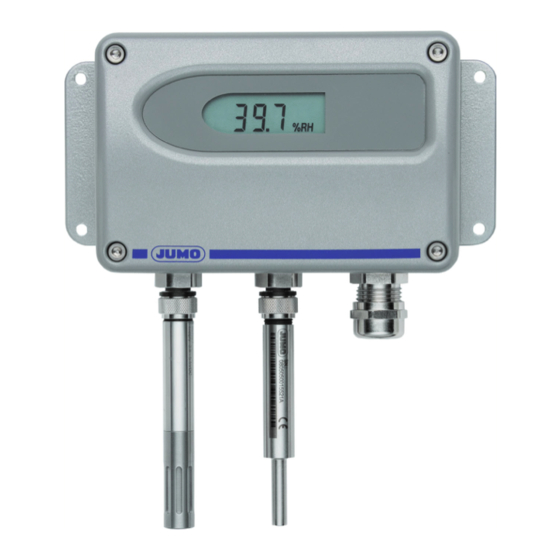
- Page 1 Capacitive Hygro-Thermo-Transmitter with intelligent and exchangeable sensors B 90.7027.1 Operating Instructions 02.08/00505282...
-
Page 3: Table Of Contents
Contents General ......................4 Symbol assertion ........................4 General safety instructions ....................4 Product description ..................4 Installation .....................5 Mounting of metal housing ....................5 Mounting of sensors ......................5 Electrical connections ..................6 Operating components .................7 Circuit board ..........................7 Display ........................... 7 Humidity-/temperature calibration ..............8 2-point humidity calibration/2-point temperature calibration ..........8 1-point humidity calibration/1-point temperature calibration ..........9 Resetting to factory calibration ....................9 Maintenance ....................10... -
Page 4: General
The manual is a part of the scope of supply and serves to ensure proper handling and optimum functioning of the instrument. JUMO doesn't accept warranty and liability claims neither upon this publication nor in case of improper treatment of the described products. -
Page 5: Installation
INSTALLATION Mounting of metal housing 1. Drill the mounting holes according to the mounting template. 2. The bottom part of the housing is mounted with 4 screws (screw diameter: < 4.2mm ; not included in the scope of supply). (0.2”) 3. -
Page 6: Electrical Connections
ELECTRICAL CONNECTIONS Voltage output Current output power supply power supply for 0 - 1 V: 10 - 35V DC 10...35V DC 9 - 29V AC Uv - 10V R < for 0 - 5 V: 12 - 35V DC 0.02 A 15 - 29V AC for 0 - 10 V: 15 - 35V DC... -
Page 7: Operating Components
OPERATING COMPONENTS Circuit board 1. JUMPER 4-20mA version 2. DISPLAY 3. CALIB LED 4. PUSH-BUTTON S1 5. PUSH-BUTTON S2 1. JUMPER: - selection of ouput and calibration mode voltage version 4-20mA version Calib selection of output 2. DISPLAY: - place for optional display 3. -
Page 8: Humidity-/Temperature Calibration
HUMIDITY-/ TEMPERATURE CALIBRATION The transmitters can be calibrated in two ways: 1-point humidity / temperature calibration: quick and simple calibration on a defined humidity / temperature point (working point). 2-point humidity / temperature calibration: simple calibration for accurate measuring results over the whole humidity / temperature working range. -
Page 9: 1-Point Humidity Calibration/1-Point Temperature Calibration
1-point humidity calibration / 1-point temperature calibration When the working range is limited to a certain more narrow range, a calibration at one humidity point / temperature point is sufficient. • In accordance with the working range, either the high or low calibration point should be selected. -
Page 10: Maintenance
MAINTENANCE Replacement of sensor The 90.7027 series are transmitters with interchangeable sensors and connectors. If the sensor gets damaged (e.g. mechanical destruction of the sensor) it is possible to replace the sensor without re-adjustment. Procedure of replacement: 1) Switch off supply voltage 2) Remove damaged sensor 3) Plug in the replacementsensor Attention: Do not mix up the position of the sensors! -
Page 11: Technical Data
TECHNICAL DATA Measuring values of sensor Relative Humidity Sensor element HC105 Working range 0...100% RH Accuracy (including hysteresis, non-linearity and repeatability, traceable to international standards, administrated by NIST, PTB, BEV...) -15...40°C <90% RH ± (1.5 + 0.5%*mv) % RH (5...104°F) -15...40°C >90% RH ±... -
Page 12: Appendix
Appendix JUMO GmbH & Co. KG Instructions for display change Street address: Moritz-Juchheim-Straße 1, 36039 Fulda, Germany Delivery address: Mackenrodtstraße 14, 36039 Fulda, Germany Postal address: 36035 Fulda, Germany Phone: +49 661 6003-0 Fax: +49 661 6003-607 e-Mail: mail@jumo.net Internet: www.jumo.net 1. -
Page 13: Application Note For Reference Sensors
Appendix Application note for reference sensors JUMO GmbH & Co. KG Street address: Moritz-Juchheim-Straße 1, 36039 Fulda, Germany Delivery address: Mackenrodtstraße 14, 36039 Fulda, Germany Postal address: 36035 Fulda, Germany Phone: +49 661 6003-0 Fax: +49 661 6003-607 e-Mail: mail@jumo.net Internet: www.jumo.net... - Page 16 JUMO GmbH & Co. KG JUMO Instrument Co. Ltd. JUMO Process Control, Inc. Street address: JUMO House 8 Technology Boulevard Moritz-Juchheim-Straße 1 Temple Bank, Riverway Canastota, NY 13032, USA 36039 Fulda, Germany Harlow, Essex CM 20 2 TT, UK Phone:...
Need help?
Do you have a question about the B 90.7027.1 and is the answer not in the manual?
Questions and answers