
Related Manuals for JUMO dTRANS T02 LCD


Summary of Contents for JUMO dTRANS T02 LCD
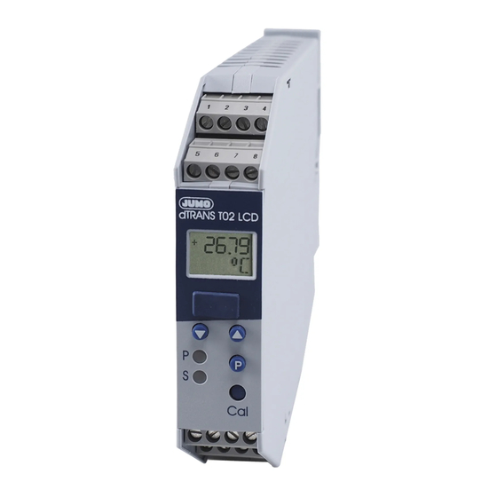
- Page 1 JdTRANS T02 LCD Programmierbarer Messumformer Programmable transmitter B 70.7022.0 Betriebsanleitung Operating Manual 03.07/00384950...
- Page 2 Bedienübersicht Normalanzeige - Messwertanzeige q > 2s q > 2s q nach letztem Parameter Parameterebene - Grenzwert Limitkomparator 1 AL1 - Grenzwert Limitkomparator 2 OUtL - Feinabgleich 0% OUtH - Feinabgleich 100 % OFFS - Teach In q > 2s q nach letztem Parameter Konfigurationsebene C111...
-
Page 3: Serienmäßiges Zubehör
1 Typenerklärung JUMO dTRANS T02 LCD (1) Grundausführung 707022 programmierbarer Messumformer (2) Eingang (programmierbar) Werkseitig eingestellt (Pt100 DIN in Vierleiterschaltung / 0 … 100°C) Konfiguration nach Kundenangaben (3) Ausgang (eingeprägter Gleichstrom - programmierbar) Werkseitig eingestellt (0 … 20mA) Konfiguration nach Kundenangaben (0/4 …... -
Page 4: Installation
2 Installation Anschlussplan Setup-Schnittstelle Bitte Hinweis “Setup- Schnittstelle” auf Seite 8 beachten. Anschluss für Spannungsversorgung lt. Typenschild Analoge Eingänge Thermoelement Widerstandsthermometer in Zweileiterschaltung R =R 30Ω (R = Gesamtleitungswiderstand) ≤ Widerstandsthermometer in Dreileiterschaltung Widerstandsthermometer in Vierleiterschaltung... - Page 5 2 Installation Potentiometer in Zweileiterschaltung 30Ω (R = Gesamtleitungswiderstand) ≤ R =R Potentiometer in Dreileiterschaltung Potentiometer in Vierleiterschaltung Widerstandsferngeber in Dreileiterschaltung Spannungseingang < 1V Spannungseingang ≥ 1V Stromeingang Analoge Ausgänge Spannungsausgang Stromausgang Strom- und Spannungsausgang sind nicht gegeneinander galvanisch ge- trennt.
- Page 6 2 Installation Digitale Ausgänge Open-Collector-Ausgang 1 Siehe “Anschlussbeispiele” auf Seite 34. Open-Collector-Ausgang 2 Siehe “Anschlussbeispiele” auf Seite 34. Setup-Schnittstelle Die Setup-Schnittstelle und der analo- ge Ausgang sind nicht galvanisch ge- trennt. Siehe “Setup-Schnittstelle” auf Seite 8. Installationshinweise Sowohl bei der Wahl des Leitungsmaterials bei der Installation als auch beim elektrischen Anschluss des Gerätes sind die Vor- schriften der VDE 0100 „Bestimmungen über das Errichten von Starkstromanlagen mit Nennspannungen unter 1000V“...
- Page 7 2 Installation Induktive Verbraucher (Relais, Magnetventile etc.) nicht in Gerä- tenähe installieren und durch RC- oder Funkenlöschkombina- tionen bzw. Freilaufdioden entstören. Eingangs-, Ausgangs- und Versorgungsleitungen räumlich von- einander getrennt und nicht parallel zueinander verlegen. Hin- und Rückleitungen nebeneinander führen und nach Möglichkeit verdrillen.
- Page 8 2 Installation Setup-Schnittstelle Die Setup-Schnittstelle und der analoge Ausgang sind nicht galvanisch getrennt. Unter ungünstigen Umständen können daher, bei einem eingebauten Messumformer, Ausgleichs- ströme fließen, wenn das PC-Interface angeschlossen wird. Die Ausgleichsströme können Schäden bei den beteiligten Geräten bewirken. Keine Gefahr besteht, wenn der Ausgangsstromkreis des Messumformers galvanisch von Erde getrennt ist.
- Page 9 2 Installation Abmessungen...
-
Page 10: Anzeige- Und Bedienelemente
3 Anzeige- und Bedienelemente LCD-Anzeige Schnittstelle für PC-Setup-Programm Tasten zur Bedienung LEDs für Betriebszustand ohne Bedeutung, nur P = Power LED für interne Zwecke S = Status LED Betriebszustand in der Leucht-/Blinkverhalten Bedienerebene (Normalbetrieb) Limitkomparator 1 inaktiv 2 inaktiv Limitkomparator 1 aktiv 2 inaktiv Limitkomparator... -
Page 11: Unterscheidung Der Betriebszustände
3 Anzeige- und Bedienelemente Betriebszustand in der Leucht-/Blinkverhalten Parameterebene (Programmier-Modus) Grenzwert von Limitkomparator 1 Grenzwert von Limitkomparator 2 Feinabgleich (Nullpunkt) Feinabgleich (Endwert) Teach In (0-%-Wert) Unterscheidung der Betriebszustände - Im Betriebszustand Bedienerebene ist die Power-LED permanent an. - Im Betriebszustand Parameterebene blinkt die Power-LED (zu gleichen Teilen an und aus). -
Page 12: Funktionen Und Bedienung
4 Funktionen und Bedienung Mit Hilfe der Tasten q, d und i in Verbindung mit der LCD-Anzei- ge und den in Kapitel 3 „Anzeige- und Bedienelemente“ bereits be- schriebenen Blinkzyklen der beiden LEDs „Power“ und „Status“ können Sie den Messumformer bedienen und programmieren. Bei der Bedienung unterscheiden sich drei Betriebszustände: - Bedienerebene (Normalbetrieb) - Parameterebene (Programmier-Modus) - Page 13 4 Funktionen und Bedienung Konfigurationsebene In die Konfigurationsebene gelangen Sie aus der Parameterebene durch Betätigen der Taste q (mindestens 2 Sekunden lang). Nur wenn in der Anzeige der Parameter OFFS aktiv ist und die Konfigurationsebene gestartet wird, können die Para- meter verändert werden.
- Page 14 4 Funktionen und Bedienung C235 - Frequenz bei Messbereichsanfang C236 - Frequenz bei Messbereichsende - Skalierung Startwert - Skalierung Endwert - Filterzeit R FE - Gesamtwiderstand bei Widerstandsferngeber C001 - Simulation Istwertausgang Die Konfigurationsebene wird verlassen (beendet), - nachdem Sie den letzten Parameter editiert haben oder - mindestens 20 Sekunden lang keine Taste betätigt wurde oder - die Tastenkombination q + d kurz betätigen.
-
Page 15: Werte Verringern
4 Funktionen und Bedienung Werte erhöhen Beim Programmieren der Parameter dient die Taste i zum Erhöhen eines Wertes (+). Werte verringern Beim Programmieren der Parameter dient die Taste d zum Verrin- gern eines Wertes (-). Werte übernehmen Wurde eine Einstellung geändert, müssen Sie die Taste q betäti- gen, um die Änderung zu übernehmen. - Page 16 4 Funktionen und Bedienung Grenzwerte (Limitkomparatoren) einstellen Sie können die beiden Grenzwerte AL1 und AL2 mit Hilfe der Tasten d und i verändern. Der aktuelle Wert wird in der LCD-Anzeige dargestellt. Es erfolgt keine Ausgabe am Analogausgang. Über- nommen wird der Wert durch Betätigen der Taste q. Die Schaltdifferenzen (Hysterese) können Sie mit den Parametern C223 und C224 bzw.
- Page 17 4 Funktionen und Bedienung Funktionsweise lk8: Natürlich lassen sich alle Parameter auch mit dem als Typenzusatz erhältlichen PC-Setup-Programm einstellen. Fehlerausgang Wird der Parameter C221 auf den Wert 3 gesetzt, findet eine Über- wachung der folgenden Fehler statt: - Fühlerbruch - Fühlerkurzschluss (nur Widerstandsthermometer) - Messbereichsüberschreitung - Messbereichsunterschreitung - interne Fehler (Pt100 der Vergleichsstelle defekt, ...)
- Page 18 4 Funktionen und Bedienung Frequenzausgang Wird der Parameter C231 auf den Wert 3 gesetzt, wird das Messsig- nal an den Klemmen des Open-Collector-Ausganges 2 als Frequenz ausgegeben (parallel zum Strom-/Spannungsausgang). Die Gren- zen des Frequenzbereiches werden durch die Parameter C235 und C236 bestimmt.
- Page 19 4 Funktionen und Bedienung Feinabgleich (Nullpunkt und Endwert) Mit Hilfe des Feinabgleiches können Sie den Nullpunkt und die Steilheit des Ausgangssignales anpassen. Auch hier wird durch Be- tätigen der Tasten d und i der jeweilige Wert verändert und durch Betätigen der Taste q übernommen. Am Ausgang wird der gemessene Istwert ausgegeben.
- Page 20 4 Funktionen und Bedienung Teach In Der Parameter „Teach In“ dient dazu, den 0-%-Wert festzulegen. Der am Eingang anliegende Istwert wird durch die „Teach In“-Pro- grammierung zum 0-%-Wert. Durch Betätigen der Tasten d oder i wird die Übernahme des Wertes ermöglicht und mit q durchgeführt. Nach einem Timeout ohne Übernahme steht der alte Wert wieder zur Verfügung.
- Page 21 5 Konfigurations- und Parametertabelle In den folgenden Konfigurations- und Parametertabellen können Sie an der durch einen markierten Stelle (Spalte) Ihre Einstellungen protokollieren. Die werkseitige Einstellung ist durch eine graue Hin- terlegung ( ) gekennzeichnet. Parameter der Parameterebene Erklärung Werte- werkseitig X Para- bereich meter...
- Page 22 5 Konfigurations- und Parametertabelle C112 Linearisierung linear kundenspezifisch Pt 100 DIN Pt 500 DIN Pt 1000 DIN Pt 100 JIS Ni 100 Ni 500 Ni 1000 Typ „L“ Typ „J“ Typ „U“ Typ „T“ Typ „K“ Typ „E“ Typ „N“ Typ „S“...
- Page 23 5 Konfigurations- und Parametertabelle C002 Einheit des Messwertes (nur wirksam, wenn Parameter C116 = 2 siehe Seite 27) Einheit LCD-Anzeige °C °C °F °F mbar mBAR mSEC 100ms 100mS ml/s mL/S ml/min mL/mn L/SEC l/min L/min m³/s m3/S m³/min m3/mn m³/h m3/H 1/SEC...
- Page 24 5 Konfigurations- und Parametertabelle C002 Einheit des Messwertes (nur wirksam, wenn Parameter C116 = 2 siehe Seite 27) Einheit LCD-Anzeige µm µm ‰ ‰ µg µG µW µW mVAs mVAS...
- Page 25 5 Konfigurations- und Parametertabelle C002 Einheit des Messwertes (nur wirksam, wenn Parameter C116 = 2 siehe Seite 27) Einheit LCD-Anzeige kVAs KVAS µJ µJ mΩ mOHM Ω kΩ KOHM MΩ MOHM mm/s mm/S mm/h mm/H m/SEC m/min m/MIN km/h Km/H m/s²...
- Page 26 5 Konfigurations- und Parametertabelle C002 Einheit des Messwertes (nur wirksam, wenn Parameter C116 = 2 siehe Seite 27) Einheit LCD-Anzeige µA µA µS µS µH µH µF µF mm² cm² m² km² kg/l KG/L µV/K µV/K...
- Page 27 5 Konfigurations- und Parametertabelle C114 Netzfrequenz / Temperatur-Kompensation 50Hz / interne Temperatur-Kompensation 50Hz / feste Temperatur-Kompensation 60Hz / interne Temperatur-Kompensation 60Hz / feste Temperatur-Kompensation Erklärung Werte- werkseitig X Para- bereich meter C115 Wert bei fester 0 … 100°C Temperatur- Kompensation C116 Messwert-Anzeige Prozent wie Ausgangssignal (mA oder V)
- Page 28 5 Konfigurations- und Parametertabelle Binär-Ausgang 1 (Open-Collector-Ausgang 1) C221 Funktion des Binär-Ausganges 1 ohne Funktion Fehlerausgang Mehr Informationen entnehmen Sie bitte “Grenzwerte (Limitkomparatoren) einstellen” auf Seite 16 und “Fehlerausgang” auf Seite 17. C222 Signal des Binär-Ausganges 1 bei Fühlerbruch/-kurzschluss aktiv inaktiv unverändert Erklärung...
- Page 29 5 Konfigurations- und Parametertabelle Binär-Ausgang 2 (Open-Collector-Ausgang 2) C231 Funktion des Binär-Ausganges 2 ohne Funktion Frequenzausgang Mehr Informationen entnehmen Sie bitte “Grenzwerte (Limitkomparatoren) einstellen” auf Seite 16 und “Frequenzausgang” auf Seite 18. C232 Signal des Binär-Ausganges 2 bei Fühlerbruch/-kurzschluss aktiv bzw. Frequenz C236 inaktiv bzw.
- Page 30 5 Konfigurations- und Parametertabelle Erklärung Werte- werkseitig X Para- bereich meter C236 Frequenz bei 10 … 1000 Messbereichsende 1000Hz Weiter Parameter Para- Erklärung Werte- werkseitig X bereich meter Skalierung Startwert -1999 … +9999 Digit Skalierung Endwert -1999 … +9999 Digit Filterzeitkonstante 0.0 …...
- Page 31 6 Hinweise ..zur Bedienung innerhalb der Parameter- und Konfigu- rationsebene Das Betätigen der Taste q als Bestätigung einer Werteinga- be setzt voraus, dass vorher ein Wert geändert wurde. Ist dies nicht der Fall, wird die Betätigung als Aufruf des nächsten Parameters angesehen.
-
Page 32: Allgemeiner Art
6 Hinweise ..allgemeiner Art Kann ein (oder kein) Parameter verändert werden, haben Sie vielleicht mit Hilfe des Setup-Programmes die Bedienung am Gerät verriegelt. Prüfen Sie die Einstellung durch das Setup-Programm. Nur, wenn die Ebene, in der sich der Parameter befindet, nicht verriegelt ist, kann der Parameter auch verändert wer- den. -
Page 33: Konfigurierbare Parameter
7 PC-Setup-Programm Mit dem als Typenzusatz erhältlichen PC-Setup-Programm lassen sich alle Parameter des Messumformers (inkl. der kundenspezifi- schen Linearisierung) bequem ändern. Über die Setup-Schnittstelle werden der Messumformer und der PC über das „PC-Interface“ miteinander verbunden. Konfigurierbare Parameter: - TAG-Number (10 Zeichen) - Analoger Eingang (Sensortyp) - Anschlussart (2-/3-/4-Leiterschaltung) - externe oder konstante Vergleichsstelle... - Page 34 8 Anschlussbeispiele Beispiel 1 Anschluss einer SPS an den Open-Collector-Ausgang Berechnungsbeispiel für R (Arbeitswiderstand) Bei dem Beispiel wird von folgenden typischen SPS-Kennwerten ausgegangen: - für Signal „1“: 13 … 30V - für Signal „0“: -3 … +5V - Eingangsstrom für Signal „1“: Bei einer angenommen Eingangsspannung von 18V/7mA für das Signal „1“...
- Page 35 8 Anschlussbeispiele Beispiel 2 Anschluss eines Relais an den Open-Collector-Ausgang...
- Page 38 JUMO GmbH & Co. KG JUMO Mess- und Regelgeräte JUMO Mess- und Regeltechnik AG Ges.m.b.H. Hausadresse: Laubisrütistrasse 70 Moltkestraße 13 - 31 8712 Stäfa, Switzerland Pfarrgasse 48 36039 Fulda, Germany Telefon: +41 44 928 24 44 1232 Wien, Austria Lieferadresse:...
- Page 39 JdTRANS T02 LCD Programmable transmitter B 70.7022.0 Operating Manual...
-
Page 40: Overview Of Operation
Overview of operation Normal display - measurement display q > 2s q > 2sec q after last parameter Parameter level - Limit for limit comparator 1 AL1 - Limit for limit comparator 2 OUtL - Fine calibration 0% OUtH - Fine calibration 100 % OFFS - Teach-in q >... -
Page 41: Type Designation
1 Type designation JUMO dTRANS T02 LCD (1) Basic version 707022 programmable transmitter (2) Input (programmable) factory-set (Pt100 DIN in 4-wire circuit / 0 — 100°C) configuration to customer specification (3) Output (proportional DC current - programmable) factory-set (0 — 20mA) configuration to customer specification (0/4 —... -
Page 42: Installation
2 Installation Connection diagram Setup interface Please refer to “Setup interface” on page 8 Connection for Supply as per nameplate Analog inputs Thermocouple Resistance thermometer in 2-wire circuit R =R 30Ω (R = total lead resistance) ≤ Resistance thermometer in 3-wire circuit Resistance thermometer in 4-wire circuit... - Page 43 2 Installation Potentiometer in 2-wire circuit 30Ω (R = total lead resistance) ≤ R =R Potentiometer in 3-wire circuit Potentiometer in 4-wire circuit Resistance transmitter in 3-wire circuit Voltage input < 1V Voltage input ≥ 1V Current input Analog outputs Voltage output Current output Current and voltage outputs are not...
-
Page 44: Installation Notes
2 Installation Digital outputs Open-collector output 1 See “Connection examples” on page 34. Open-collector output 2 See “Connection examples” on page 34. Setup interface The setup interface and the analog out- put are not electrically isolated. See “Setup interface” on page 8. Installation notes The choice of cable, the installation and the electrical connec- tions must conform to the requirements of VDE 0100 “Regula-... - Page 45 2 Installation Do not install inductive loads (relays, solenoid valves etc.) close to the instrument. Use RC networks, spark quenchers or free- wheel diodes for interference suppression. Route input, output and supply cables separately, and not par- allel to each other. Run out and return cables next to each other and twisted, if possible.
-
Page 46: Setup Interface
2 Installation Setup interface The setup interface and the analog output are not electrical- ly isolated. This means that under adverse conditions and with a built-in transmitter, equalizing currents may flow when the PC interface is connected. These equalizing cur- rents may damage the affected instruments. - Page 47 2 Installation Dimensions...
-
Page 48: Displays And Controls
3 Displays and controls LCD display interface for PC setup program buttons for operation LEDs for operational status without significance, P = Power LED for internal purposes S = Status LED only Operational status at the Illumination/blink behavior operating level (normal operation) Limit comparator 1 inactive... -
Page 49: Differentiation Of The Operational States
3 Displays and controls Operational status at the Illumination/blink behavior parameter level (programming mode) Limit for limit comparator 1 Limit for limit comparator 2 Fine calibration (zero) Fine calibration (full scale) Teach-in (0 % value) Differentiation of the operational states - in the Operating level status, the power LED is on permanently. -
Page 50: Functions And Operation
4 Functions and operation You can operate and program the transmitter by using the q, d and i buttons in conjunction with the LC display and the blink cy- cles of the “Power” and “Status” LEDs, which have already been described in Chapter 3 “Displays and controls”. - Page 51 4 Functions and operation Configuration level You can access the configuration level from the parameter level by pressing the q button (for at least 2 seconds). The parameters can only be modified when the parameter OFFS is active in the display and the configuration level has been started.
- Page 52 4 Functions and operation C235 - Frequency at the range start C236 - Frequency at the range end - Start value for scaling - End value for scaling - Filter time R FE - Total resistance for resistance transmitter C001 - Simulation of measurement output The configuration level is exited (quit) - after editing the last parameter,...
-
Page 53: Decrementing Values
4 Functions and operation Incrementing values When programming the parameters, the i button is used to in- crease a value (+). Decrementing values When programming the parameters, the d button is used to de- crease a value (-). Accepting values If a setting has been altered, the q button has to be pressed to ac- cept the alteration. -
Page 54: Setting The Limit Values (Limit Comparators)
4 Functions and operation Setting the limit values (limit comparators) You can alter the two limit values AL1 and AL2 by using the d and i buttons. The present value will be shown on the LC display; it is not output via the analog output. -
Page 55: Fault Output
4 Functions and operation Function lk8: Of course, all parameters can also be set using the PC setup pro- gram, which is available as an extra. Fault output If the parameter C221 is set to the value 3, then the following errors are monitored: - probe break - probe short-circuit (resistance thermometer only) - Page 56 4 Functions and operation Frequency output If the parameter C231 is set to the value 3, the measurement signal is output as a frequency at the terminals of the open-collector out- put 2 (parallel to the current/voltage output). The limits of the fre- quency range are determined by the parameters C235 and C236.
-
Page 57: Fine Calibration (Zero Point And Full Scale)
4 Functions and operation Fine calibration (zero point and full scale) Fine calibration can be used to adjust the zero point and the slope of the output signal. Here, too, the d and i buttons are available for altering the appropriate value, and for accepting it by pressing the q button. - Page 58 4 Functions and operation Teach-in The “Teach-in” parameter serves to define the 0% value. The actual value that is present at the output will become a 0% value through “Teach-in” programming. This value is accepted by pressing the d or i button and executed with q.
- Page 59 5 Configuration and parameter tables You can record your settings in the configuration and parameter ta- bles below, in the position (column) marked with . The factory settings are shown on a gray background ( Parameters at the parameter level Para- Explanation Value range factory...
- Page 60 5 Configuration and parameter tables C112 Linearization linear customized Pt 100 DIN Pt 500 DIN Pt 1000 DIN Pt 100 JIS Ni 100 Ni 500 Ni 1000 Type L Type J Type U Type T Type K Type E Type N Type S Type R Type B...
- Page 61 5 Configuration and parameter tables C002 Unit of measurement (only effective if parameter C116 = 2 see page 27) Unit LCD display °C °C °F °F mbar mBAR mSEC 100ms 100mS ml/s mL/S ml/min mL/mn L/SEC l/min L/min m³/s m3/S m³/min m3/mn m³/h...
- Page 62 5 Configuration and parameter tables C002 Unit of measurement (only effective if parameter C116 = 2 see page 27) Unit LCD display µm µm ‰ ‰ µg µG µW µW mVAs mVAS...
- Page 63 5 Configuration and parameter tables C002 Unit of measurement (only effective if parameter C116 = 2 see page 27) Unit LCD display kVAs KVAS µJ µJ mΩ mOHM Ω kΩ KOHM MΩ MOHM mm/s mm/S mm/h mm/H m/SEC m/min m/MIN km/h Km/H m/s²...
- Page 64 5 Configuration and parameter tables C002 Unit of measurement (only effective if parameter C116 = 2 see page 27) Unit LCD display µA µA µS µS µH µH µF µF mm² cm² m² km² kg/l KG/L µV/K µV/K...
- Page 65 5 Configuration and parameter tables C114 Supply frequency/temperature compensation X 50Hz / internal temperature compensation 50Hz / fixed temperature compensation 60Hz / internal temperature compensation 60Hz / fixed temperature compensation Explanation Value range factory Para- setting meter C115 value with fixed 0 —...
- Page 66 5 Configuration and parameter tables Logic output 1 (open-collector output 1) C221 Function of the logic output 1 no function fault output You will find additional information in “Setting the limit values (limit comparators)” on page 16 and “Fault output” on page 17 C222 Signal of logic output 1 on probe break/short-circuit active...
- Page 67 5 Configuration and parameter tables Logic output 2 (open-collector output 2) C231 Function of the logic output 2 no function Frequency output You will find additional information in “Setting the limit values (limit comparators)” on page 16 and “Frequency output” on page 18 C232 Signal of the logic output 2 on probe break/short-circuit active or frequency C236...
- Page 68 5 Configuration and parameter tables Explanation Value range factory Para- setting meter C236 Frequency at 10 — 1000 range end 1000Hz Additional parameters Para- Explanation Value range factory setting meter Scaling start value -1999 to +9999 digit Scaling end value -1999 to +9999 digit Filter time constant...
- Page 69 6 Tips ..on operation within the parameter and configuration levels Pressing the q button to confirm a value entry requires that a value has previously been modified. If this is not the case, the confirmation will be interpreted as a call of the next parameter.
- Page 70 6 Tips ..of a more general nature If none of the parameters can be modified, then you may have locked the operation on the instrument through the setup program. Please check the setting using the setup program. The parameter can only be modified if the level at which the parameter can be found is not inhibited.
-
Page 71: Pc Setup Program
7 PC setup program The PC setup program, which is available as an extra, can be used to modify all parameters of the transmitter (including the custom lin- earization) with ease. Through the setup interface, the transmitter and the PC are linked via the “PC interface”. Configurable parameters - TAG number (10 characters) - analog input (sensor type) -
Page 72: Connection Examples
8 Connection examples Example 1 Connecting a PLC to the open-collector output Calculation example for R (working resistance) In this example, the following typical PLC characteristics are as- sumed: - for signal “1”: 13 — 30V - for signal “0”: -3 to +5V - input current for signal “1”: An assumed input voltage of 18V/7mA for signal “1”... - Page 73 8 Connection examples Example 2 Connecting a relay to the open-collector output...
- Page 76 JUMO GmbH & Co. KG JUMO Instrument Co. Ltd. JUMO Process Control, Inc. Street address: JUMO House 8 Technology Boulevard Moltkestraße 13 - 31 Temple Bank, Riverway Canastota, NY 13032, USA 36039 Fulda, Germany Harlow, Essex CM20 2TT, UK Phone:...
Need help?
Do you have a question about the dTRANS T02 LCD and is the answer not in the manual?
Questions and answers