Chapters
Table of Contents

Related Manuals for JUMO dTRANS T01 HART


Summary of Contents for JUMO dTRANS T01 HART
- Page 1 T01 dTRANS T01 T 707011/... 707013/... ® J dTRANS T01 HART Programmierbarer Zweidraht-Messumformer Programmable 2-wire transmitter B 70.7011.0 Betriebsanleitung Operating Instructions 12.05/00387995...
-
Page 3: Table Of Contents
Inhalt Typenerklärung ............4 JUMO dTRANS T01 HART ............4 Serienmäßiges Zubehör............4 Zubehör..................4 Installation ..............5 Anschluss und Abmessung Typ 707011/.........5 Anschluss und Abmessung Typ 707013/.........6 Anschlussbeispiel mit Speisetrenner ........7 Anschlussbeispiel mit Netzgerät..........7 ® HART -Schnittstelle ..........8 ®... -
Page 4: Typenerklärung
1 Typenerklärung JUMO dTRANS T01 HART (1) Grundausführung programmierbarer Zweidraht-Messumformer 707011 ® mit HART -Schnittstelle programmierbarer Zweidraht-Messumformer ® 707013 mit HART -Schnittstelle montiert in Tragschienengehäuse (2) Eingang (programmierbar) Werkseitig eingestellt (Pt100 DIN vl) Konfiguration nach Kundenangaben (3) Ausgang (eingeprägter Gleichstrom) Werkseitig eingestellt (4 …... -
Page 5: Installation
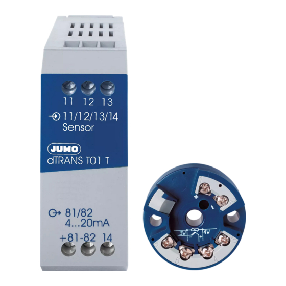
2 Installation Anschluss und Abmessung Typ 707011/... Anschluss für Anschlussbelegung Spannungs- – ------------------- - versorgung 22mA DC 10 ... 35V bzw. = Bürdenwiderstand Stromausgang = Spannungs- 4 ... 20mA versorgung Analoge Eingänge Thermoelement ≤ Widerstands- 11Ω thermometer = Leitungswider- in Zweileiter- stand je Leiter schaltung ≤... -
Page 6: Anschluss Und Abmessung Typ 707013
2 Installation Anschluss und Abmessung Typ 707013/... C-rail 15mm EN 60 715 C-rail 35mm x 7.5mm EN 60 715 G-rail EN 60 715 Anschluß für Anschlußbelegung Spannungs- – ---------------- - versorgung 81 82 22mA DC 8 ... 35V = Bürdenwiderstand bzw. -
Page 7: Anschlussbeispiel Mit Speisetrenner
2 Installation Anschlussbeispiel mit Speisetrenner Regler Anzeige- Registrier- gerät gerät Zweidraht- Speise- Messumformer trenner 4...20 mA 4...20 mA / 0...20 mA 0...10 V Anschlussbeispiel mit Netzgerät Regler Anzeige- Registrier- gerät gerät Zweidraht- Netzgerät Messumformer DC 10...30 V 4...20 mA... -
Page 8: Hart
® 3 HART -Schnittstelle ® Anschluss eines HART -Modems ® Mit dem HART -Modem kann der Messumformer mit einem PC verbunden werden. Das Modem wird auf Wunsch gegen Mehrpreis geliefert : Verkaufs-Artikel-Nummer: 40/00345666 Spannungsversorgung Messumformer DC 10…35V dTRANS T01 Bürde 1 bis zu 15 Messumformer (Multidrop) Ò... -
Page 9: Setup-Programm
4 Setup-Programm Das Setup-Programm dient zur Konfiguration des Messumformers ® mit Hilfe eines PC. Der Anschluss erfolgt über das HART -Modem. Konfigurierbare Parameter: - TAG-Number (8 Zeichen), 16 Zeichen Beschreibung und 32 Zeichen Nachricht - Sensortyp, Linearisierung - Anschlussart (2-/3-/4-Leiterschaltung) - interne Vergleichsstelle oder externe Vergleichsstelle (Festwert) - kundenspezifische Linearisierung... -
Page 10: Hardware- Und Software-Voraussetzungen
4 Setup-Programm Hardware- und Software-Voraussetzungen Für den Betrieb und die Installation des Setup-Programms müssen folgende Hardware- und Software-Voraussetzungen erfüllt sein: - IBM-PC oder kompatibler PC ab 486DX-2-100 - 16 MB Hauptspeicher - 15MB freier Festplattenspeicher - CD-ROM-Laufwerk - 1 freie serielle Schnittstelle - Windows 95 oder höher, Windows NT4.0 oder Windows 2000... -
Page 11: Technische Daten
5 Technische Daten... - Page 12 5 Technische Daten...
- Page 13 5 Technische Daten...
- Page 14 5 Technische Daten...
- Page 15 5 Technische Daten...
- Page 18 JUMO GmbH & Co. KG JUMO Mess- und Regelgeräte JUMO Mess- und Regeltechnik AG Ges.m.b.H. Hausadresse: Laubisrütistrasse 70 Moltkestraße 13 - 31 8712 Stäfa, Switzerland Pfarrgasse 48 36039 Fulda, Germany Telefon: +41 44 928 24 44 1232 Wien, Austria Lieferadresse:...
-
Page 19: Operating Instructions
T01 dTRANS T01 T 707011/... 707013/... ® J dTRANS T01 HART Programmable 2-wire transmitter B 70.7011.0 Operating Instructions... - Page 21 Contents Type designation ............4 JUMO dTRANS T01 HART ............4 Standard accessories ...............4 Accessories................4 Installation ..............5 Connections and dimensions, type 707011/......5 Connections and dimensions, type 707013/......6 Connection example with supply isolator.........7 Connection example with supply unit........7 ®...
-
Page 22: Type Designation
1 Type designation JUMO dTRANS T01 HART (1) Basic version programmable 2-wire transmitter 707011 ® with HART interface programmable 2-wire transmitter ® 707013 with HART interface installed in rail-mounting housing (2) Input (programmable) factory-set (Pt100 DIN vl) configuration to customer specification (3) Output (proportional DC current) factory-set (4 —... -
Page 23: Installation
2 Installation Connections and dimensions, type 707011/... Connection for Terminals Supply – ------------------- - 10 — 35V DC 22mA current output = burden resistance 4 — 20mA = supply voltage Analog inputs Thermocouple ≤ Resistance 11Ω thermometer = lead resistance in 2-wire per conductor circuit... -
Page 24: Connections And Dimensions, Type 707013
2 Installation Connections and dimensions, type 707013/... C-rail 15mm EN 60 715 C-rail 35mm x 7.5mm EN 60 715 G-rail EN 60 715 Connection for Terminals Supply – ---------------- - 8 — 35V DC 81 82 22mA = burden resistance –... -
Page 25: Connection Example With Supply Isolator
2 Installation Connection example with supply isolator Controller Indicator Recorder 2-wire Supply transmitter isolator 4—20 mA 4—20 mA / 0—20 mA 0—10 V Connection example with supply unit Controller Indicator Recorder 2-wire Supply unit transmitter 10—30 V DC 4—20 mA... -
Page 26: Hart
® 3 HART interface ® Connecting a HART modem ® The transmitter can be linked to a PC via the HART modem. The modem can be supplied to special order, at extra cost: Sales No. 40/00345666 Supply Transmitter 10—35V DC dTRANS T01 Burden 1 up to 15 transmitters... -
Page 27: Setup Program
4 Setup program The setup program is available for configuring the transmitter from a ® PC. The connection is made via the HART modem. Configurable parameters: - TAG number (8 characters), 16 characters for the description and 32 characters for the message - sensor type, linearization - connection circuit (2-/3-/4 wire) - internal cold junction or... -
Page 28: Hardware And Software Requirements
4 Setup program Hardware and software requirements The following hardware and software requirements have to be met for operating and installing the setup program: - IBM-PC or compatible PC from 486DX-2-100 - 16 MB main memory - 15MB available on hard disk - CD-ROM drive - 1 free serial interface - Windows 95 or higher, Windows NT4.0 or Windows 2000... -
Page 29: Technical Data
5 Technical data... - Page 30 5 Technical data...
- Page 31 5 Technical data...
- Page 32 5 Technical data...
- Page 33 5 Technical data...
- Page 36 JUMO GmbH & Co. KG JUMO Instrument Co. Ltd. JUMO Process Control, Inc. Street address: JUMO House 8 Technology Boulevard Moltkestraße 13 - 31 Temple Bank, Riverway Canastota, NY 13032, USA 36039 Fulda, Germany Harlow, Essex CM20 2TT, UK Phone:...
Need help?
Do you have a question about the dTRANS T01 HART and is the answer not in the manual?
Questions and answers