
Related Manuals for JUMO ecoTRANS Lf 01


Summary of Contents for JUMO ecoTRANS Lf 01
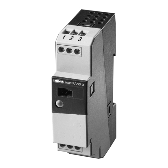
- Page 1 Lf 01/02 Transmitter / Switching Device for Conductivity Type 202731 B 20.2731.0 Operating Instructions 02.07/00435548...
-
Page 3: Table Of Contents
Altering the device functions _________________________________ 12 6.3.1 Operation through the Setup __________________________________ 13 6.3.2 Operation through the teach-in connector (only on the JUMO ecoTRANS Lf 02) ___________________________ 15 Calibration _________________________________________________ 17 6.4.1 Characteristics of sensor and medium _______________________ 18 6.4.2 Preparing to calibrate the cell constant or temperature coefficient _ 19 6.4.3 Calibrating the cell constant ________________________________ 20... -
Page 4: Notes
Keep the manual in a place which is accessible to all users at all times. Please assist us to improve these operating instructions, where necessary. Phone + 49 661 6003-0 + 49 661 6003-607 E-mail: Service@jumo.net... -
Page 5: Identifying The Device Version
The nameplate with the order code is glued to the side of the housing. The supply voltage must correspond to the voltage given on the nameplate. 2.1 Type designation (1) Basic type 202731 JUMO ecoTRANS Lf 01/02, Microprocessor transmitter / switching device for conductivity (2) Output with analog output with relay output (3) Measuring range (freely programmable) 0 —... -
Page 6: Mounting
3 Mounting °C 34.5 51.5 4 Electrical connection The choice of cable, the installation, the fusing and the electrical connection must conform to the requirements of VDE 0100 “Regulations on the Installation of Power Circuits with Nominal Voltages below 1000 V” or the appropriate local regulations. To protect the instrument from electrostatic discharge, users must discharge themselves electrostatically before touching the instrument! - Page 7 lead to damage. Safety devices should always be provided that are independent of the instrument (such as overpressure valves or temperature monitors/limiters) and only capable of adjustment by specialist personnel. Please observe the relevant safety regulations for such matters. The load circuit must be fused for the maximum relay current, in order to prevent the output relay contacts becoming welded in the event of a short circuit.
-
Page 8: Electrical Connection
5 Electrical connection Setup connection or connection for the teach-in connector (on the JUMO ecoTRANS Lf 02) LED for the indication of operating states Head of a JUMO conductivity cell with Hirschmann connector Head of a JUMO conductivity cell with... - Page 10 Outputs Terminal assignments Symbol Analog measurement output (electrically isolated) only with JUMO ecoTRANS Lf 01 Relay n.c. (break) common Ö n.o. (make) only with JUMO ecoTRANS Lf 02 Measurement Terminal assignments Symbol inputs Conductivity outer electrode, cell on coaxial cells...
-
Page 11: Commissioning
If the device has been connected correctly, the LED will light up. - green, constant status display - red, constant the relay is active (only on the JUMO ecoTRANS Lf 02) - red, flashing alarm - measuring range infringed (overrange) - temperature range infringed (over/underrange) - temperature probe not connected correctly also see Chapter 6.9 “LED messages”, page 27. -
Page 12: Altering The Device Functions
6.3 Altering the device functions Alterations can only be carried out in the setup program. Exception: the switching point of the JUMO ecoTRANS Lf 02 can also be determined by the device, through the teach-in connector. Operation via the setup interface... -
Page 13: Operation Through The Setup
6.3.1 Operation through the Setup (1) Navigation tree The navigation tree allows quick access (double-click) to the individual setting options. (2) Diagnosis window A soon as a connection with a device has been established, the latest data are shown here. (3) Working area If you click on the arrow ( ), the setting options will be shown. - Page 14 (e.g. 2-wire), reference temperature and so on. Analog output (JUMO ecoTRANS Lf 01 only) In this window, you can make settings concerning the analog output for conductivity, such as current/voltage output, scaling and so on.
-
Page 15: Operation Through The Teach-In Connector
2% of the measuring range. A range with the correct cell constant must have been configured. Procedure - The JUMO ecoTRANS Lf 02 is operating (a conductivity cell has been attached, the supply voltage has been connected). Immerse the conductivity cell into a solution with a known (desired) conductivity. - Page 16 If the switching point has been found: Pull out the teach-in plug. The device operates with the switching point that has been learned. If the switching point has not been found: Pull out the teach-in plug. The device operates with the original switching point. Note The learning mode can be activated by plugging the teach-in connector in again.
-
Page 17: Calibration
Example JUMO ecoTRANS Lf 02 with the range 0 — 2 mS/cm; cell constant K = 1.0 desired switching point w = 0.8 mS/cm = (0.0008 S/cm) = 1250 Ω 0.0008 The resistance that must be connected in place of the conductivity cell has a value of 1250 Ω. -
Page 18: Characteristics Of Sensor And Medium
6.4.1 Characteristics of sensor and medium The “Characteristics of sensor and medium” window is called up with the “screwdriver” icon. The data can be manually entered here or determined empirically and transferred to the device using an integrated routine. -
Page 19: Preparing To Calibrate The Cell Constant Or Temperature Coefficient
6.4.2 Preparing to calibrate the cell constant or temperature coefficient Connect the conductivity cell to the JUMO ecoTRANS Lf 01/02. Connect the JUMO ecoTRANS Lf 01/02 to the PC or laptop by means of the PC interface cable (Part No. TN 95/00350260). Caution The PC or notebook must not be electrically connected to ground or connected to a network, see page 12. -
Page 20: Calibrating The Cell Constant
6.4.3 Calibrating the cell constant The sequence is defined by the setup program. Immerse the conductivity cell into a solution with a known conductivity. In the setup program, start “Calibration of the cell constant” by activating the “Relative cell constant” button. Accept the calculated cell constant with “Yes”... -
Page 21: Manual Entry Of Temperature Coefficient And Cell Constant
The calculated value will be displayed at the end of the routine. Note Wait until the temperature measurement is stable, i.e. observe the time of the temperature probe. A waiting time of about 5 minutes has proved to be useful in pratice. If the calibration of the temperature coefficient has been concluded with “Yes”, the calibration timer is reset and restarted. -
Page 22: Manual Mode
6.6 Manual mode This function can be used to manually control the analog output or relay. Note On leaving the manual mode, the outputs behave in accordance with the defined parameters. -
Page 23: Analog Output (Jumo Ecotrans Lf 01)
6.7 Analog output (JUMO ecoTRANS Lf 01) Response after switching on the supply voltage During switch-on (about 2 sec), the output signal is 0 V or 0 mA. Response during calibration You can choose between “following” or “unchanged” (constant). Response of the output signal in fault condition Depending on the type of error, the output signal can adopt the “LOW”... - Page 24 Response of the output signal on leaving the scaling range As per NAMUR NE43 recommendation, the output signal of the JUMO ecoTRANS Lf01 adopts the following defined values on going above or below the scaling range: below scaling range within scaling...
-
Page 25: Relay Output (Jumo Ecotrans Lf 02)
During switch-on (about 2 sec), the relay is in the de-energized condition (inactive). Response of the relay Depending on the setting (through the setup program), the JUMO ecoTRANS Lf 02 monitors a limit, similar to a limit comparator (LK), as a MAX or MIN LK. - Page 26 Manual operation of the relay The relay can be manually set to “active” or “inactive” in the setup program. When leaving the manual mode, the switching condition of the relay will depend on the conductivity and the limit, see Chapter 6.6 “Manual mode”, page 22. Response of the relay during calibration and in fault condition The setup program can be used to set the relay response to - relay unchanged...
-
Page 27: Led Messages
- infringement of temperature range (over/underrange) or - infringement of conductivity range (overrange) - teach-in operation: switching point not found green/red light flash calibration timer has run down: alternately the JUMO ecoTRANS Lf 01/02 is due for recalibration (cell constant and/or temperature coefficient) -
Page 28: Technical Data
7 Technical data Analog input 1 (conductivity) Electrolytic conductivity cells with the cell constants 0.01; 0.1; 1.0; 10.0 (2-electrode principle). The cell constant can be adjusted over the range 20 — 500%. Lead compensation, analog input 1 The effect of long cables can be compensated on ranges above about 20 mS/cm by entering the resistance of the incoming cable, within the range 0.00 to 99.99 Ω. - Page 29 Deviation from characteristic, temperature with Pt100 and Pt1000: ≤ 0.6% of range with customized characteristic ≤ 5 Ω Outputs JUMO ecoTRANS Lf 01 (analog output): freely configurable: ≥ 2 kΩ or 0(2) — 10V load ≥ 2 kΩ or 10 — 0(2)V load ≤...
-
Page 30: General Characteristics
JUMO ecoTRANS Lf 02 (relay output): changeover contact contact rating: 4 A, 250 V AC, with resistive load 24 V DC, with resistive load current rating: contact life: > 100,000 operations at rated load 7.1 General characteristics A/D converter resolution 14 bit... -
Page 31: Environment / Waste Disposal
DIN rail mounting: PC (polycarbonate) Mounting on 35 x 7.5 mm DIN rail to EN 60 715 Operating position unrestricted Weight approx. 110g 8 Environment / waste disposal Faulty devices can be returned to JUMO for proper disposal. - Page 32 JUMO GmbH & Co. KG JUMO Instrument Co. Ltd. JUMO Process Control, Inc. Street address: JUMO House 8 Technology Boulevard Moltkestraße 13 - 31 Temple Bank, Riverway Canastota, NY 13032, USA 36039 Fulda, Germany Harlow, Essex CM20 2TT, UK Phone:...
Need help?
Do you have a question about the ecoTRANS Lf 01 and is the answer not in the manual?
Questions and answers